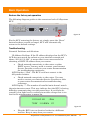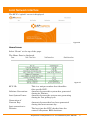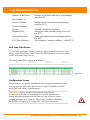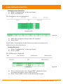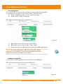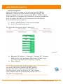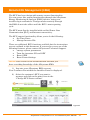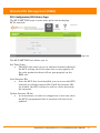
1
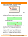
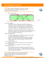
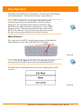
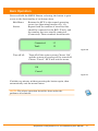
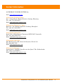
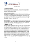
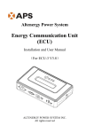
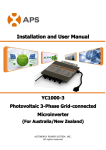
Installation / User Manual APsystems Three-phase ECU-3 (V3) Three-phase Energy Communication Unit Rev 3.0 © All Rights Reserved Table of Contents Introduction............................................................................................................... 2 Interface Explanation.................................................................................................3 Interface position.............................................................................................................3 Power Interface................................................................................................................3 RS232 Serial Port..............................................................................................................3 Network Port....................................................................................................................4 USB Interface................................................................................................................... 4 Reset................................................................................................................................ 4 Hardware Installation................................................................................................ 5 Preparation...................................................................................................................... 5 Selecting an Installation Location for the ECU.................................................................5 Cable Connections........................................................................................................... 7 Internet Connection.........................................................................................................7 Connect the AC Power Line..............................................................................................8 ECU Initialization Sequence.......................................................................................9 Step 1: Power on ECU...................................................................................................... 9 Step 2: ECU time zone setting........................................................................................11 Step 3: EMA Monitoring................................................................................................ 11 Basic Operation........................................................................................................12 Menu Structure..............................................................................................................12 Restore the factory set operation.................................................................................. 14 Troubleshooting............................................................................................................. 14 Local Network Interface.......................................................................................... 15 Connecting to the ECU via the LAN................................................................................15 Connecting Directly to the ECU......................................................................................15 Home Screen..................................................................................................................17 Real-time Data Screen....................................................................................................18 Configuration Screen..................................................................................................... 18 Administration Screen....................................................................................................20 Remote ECU Management (EMA)........................................................................... 26 ECU Configuration/ECU Status Page..............................................................................27 Setting the ECU Time Zone............................................................................................ 28 Managing Inverter IDs and Updating the Inverter ID List..............................................28 Technical Data.......................................................................................................... 30 APsystems Three-phase ECU-3 V3 Installation/User Manual 1 Introduction The APsystems Communicator, our state-of-the-art Energy Communication Unit (ECU), is the information gateway for our microinverters. The unit collects module performance data from each individual microinverter and transfers this information to an Internet database in real time, requiring only a single data and power cable. Through the APsystems Monitor software, the APsystems Communicator gives you precise analysis of each microinverter and module in your solar installation from any web-connected device. The APsystems Communicator’s integrated http webserver offers the simplest and most flexible network integration of any data logger on the market. The user-friendly browser-based interface lets you access your solar array in seconds. Features Collects individual module and microinverter statistics Communicates in real time Requires no additional wiring The APsystems Microinverter is used in utility-interactive grid-tied applications, and is made up of three key elements: APsystems Microinverter APsystems Energy Communication Unit (ECU) APsystems Energy Monitor and Analysis (EMA) web-based monitoring and analysis system Figure 1 APsystems Three-phase ECU-3 V3 Installation/User Manual 2 Interface Explanation Interface position All of the ECU interface as below, from left to right, are power connection port, serial port, network port, USB interface and reset. Power Interface RS232 Serial port Network port USB interface Reset Figure 2 Power Interface Power interface connects power through the power line. Figure 3 RS232 Serial Port You can connect GPRS module to RS232 serial port, select GPRS module to connect to the network on “Network Connectivity” page, and communicate with the EMA, to check the system data. Figure 4 APsystems Three-phase ECU-3 V3 Installation/User Manual 3 Interface Expalnation Network Port RJ45 Ethernet network port: ECU allows user to communicate with EMA, and log in ECU's local page, set up the system and view the system data via Ethernet network port. In the case of the absence of the wired network, user can select optional WiFi-Bridge wireless Internet. Figure 5 USB Interface In the case of the absence of the wired network, user can select optional WiFi-Bridge wireless Internet. USB interface only provides 5V DC power supply for the WiFi-Bridge. Reset Press the “Reset” button for three seconds or longer, ECU will automatically return to the default settings. NOTE: The historical power generation won't be cleared. APsystems Three-phase ECU-3 V3 Installation/User Manual 4 Hardware Installation Preparation Make sure you have the following things taken care of before attempting to install the ECU: Three-phase AC power line. A broadband Internet connection is available for your use. A broadband router with either a CAT5 Ethernet, or wireless router is available for your use. A laptop with a web browser (to view the APsystems EMA online monitoring application). A pre-programmed Three-phase ECU. Selecting an Installation Location for the ECU 1) A location that is electrically as close to the array as is possible-preferably a dedicated outlet installed directly to the solar system sub-panel. The ECU is NOT rated for outdoor use, so if installing outdoors near a junction box or breaker panel, making sure that you enclose it in an appropriate weather proof NEMA electrical box. Using Electrical Mounting Din Rail Loosen the two (2) M3 mounting screws on the back of the ECU and rotate the two (2) rail holders so that the holders are above the ECU. 182mm 42mm Holder 125mm M3 Screw Figure 6 APsystems Three-phase ECU-3 V3 Installation/User Manual 5 Hardware Installation Attach the ECU to the mounting rail with machine screws. 80mm 138mm Figure 7 2) Using Wall Mount When mounting the ECU to a wall, make sure to select a cool, dry, indoor location. Depending on the wall surface you are mounting the ECU to, use either two (2) #8 drywall screws or wall anchors, installed 130 mm apart. The drywall screws and wall anchors are NOT included in the ECU kit. Align and slide the ECU onto the mounting screws. 130mm Figure 8 Best Practice: Install and connect the ECU to the Internet (see below instructions) while the rest of the array is being installed. Doing so allows the ECU to automatically update its internal software while the rest of the physical installation is underway. The ECU will then communicate with the inverters when the installation is complete and the array is energized. APsystems Three-phase ECU-3 V3 Installation/User Manual 6 Hardware Installation Cable Connections Power Interface Network port Figure 9 Connect the power cable to the power interface on the bottom of the ECU. Connect the supplied LAN cable to the network port on the bottom of the ECU. Internet Connection There are three different approaches to connecting the ECU to the Internet: Option 1: Direct LAN cable connection. 1) Make sure the LAN cable is connected to the network port on the bottom of the ECU. 2) Connect the LAN cable into a spare port on the broadband router. Figure 10 Option 2: Wireless Connection. Using a wifi extender: 1) Make sure the LAN cable is connected to the network port on the bottom of the ECU. 2) Connect the LAN cable into the wifi extender. Figure 11 Option 3: Using a PLC bridge 1) Make sure the LAN cable is connected to the network port on the bottom of the ECU. APsystems Three-phase ECU-3 V3 Installation/User Manual 7 Hardware Installation 2) 3) Connect the LAN cable into the “send” unit of the PLC bridge. Connect a LAN cable from the “receive” unit of the PLC bridge into a spare port on the broadband router (refer to bridge users manual for specific operating instructions). Figure 12 NOTE: 1. The ECU is NOT a wireless device and requires a wifi extender or bridge to make the connection to a wireless router. 2. A PLC bridge uses the power line to communicate and requires both a “send” and “receive” unit. Connect the AC Power Line Make sure the power cable is correctly connected to the power interface on the bottom of the ECU. Figure 13 N L3 L2 L1 PE APsystems Three-phase ECU-3 V3 Installation/User Manual 8 ECU Initialization Sequence Once power is supplied to the ECU, it automatically steps through a series of initialization screens on its LCD display. LCD Display Figure 14 Step 1: Power on ECU The following information will be displayed on LCD after ten seconds. 1) Loading the software firmware: Loading… Figure 15 2) Searching for the inverters: Firmware Version Searching V3.10 192.168.2.101 Figure 16 Router IP Address A word about network communication protocols. The ECU needs to have access to the router via an IP address. The ECU will only search for and obtain a Dynamic Host Configuration Protocol (DHCP) IP address during its powering up sequence. For example, the LCD screen on the front of the ECU displays an IP address such as “192.168.2.101”, if the connection to the router is successful (the IP address will vary based on router supplier, so check with the user manual for specifics). If, however, the LED displays “60.190.131.228”, the ECU-router connection has not been successful, in which case you’ll need to check all of the cabling connections and reboot the ECU by removing the power cable for a few seconds and reconnecting. APsystems Three-phase ECU-3 V3 Installation/User Manual 9 ECU Initialization Sequence NOTE: The complete initialization sequence can take several minutes (up to 15 minutes depending on the complexity of the installation). 3) Operation interface: Router IP Address 192.168.2.101 EMA Communication +Web 750W 11.54Kwh 12 Figure 17 Current Power Production Lifetime Production Reporting Inverters Router IP Address: The LCD screen on the front of the ECU displays an IP address such as “192.168.2.101”, if the connection to the router is successful (the IP address will vary based on router supplier, so check with the user manual for specifics). If, however, the LED displays “60.190.131.228”, the ECU-router connection has not been successful, in which case you’ll need to check all of the cabling connections and reboot the ECU by removing the power cable for a few seconds and reconnecting. EMA Communication: A “+Web” indicates that the ECU is communicating with the APsystems EMA via the Internet. “-Web” is an indication that there is a problem and the ECU is not communicating with the APsystems EMA. Need to setup the security authority to offer Auto IP configuration. Current Power Production: What the solar array is producing currently (in Watts). Lifetime Production: The lifetime power output of the system (in kWh). Reporting Inverters: The number of inverters reporting into the ECU. If the number is followed by an “!”, then the number of reporting inverters does not match the number of IDs that have been programmed into the ECU. NOTE: The inverter IDs must be programmed into the ECU for the ECU to recognize the inverters. The ECU will NOT auto-sense the inverters (see ID Management pg. 20). APsystems Three-phase ECU-3 V3 Installation/User Manual 10 ECU Initialization Sequence Step 2: ECU time zone setting Enter the IP address shown on the ECU LCD into the internet browser, and then open the web page. Click “Administration”, then “Date, Time, Time zone”. In the corresponding box, enter local date/time/time zone, click Update after finished. For details, refer to time management on pg.24. Step 3: EMA Monitoring After ECU display “+Web”,contact APsystems technical staffs in your local area and they will setup an EMA account with User Name and Password, then complete EMA management(see pg.30). APsystems Three-phase ECU-3 V3 Installation/User Manual 11 Basic Operation The APsystems ECU has one two-line, 40-character LCD display with alphanumeric. Set the mode using a single button. NOTE: ECU functions as a gateway and monitors the microinverters that are connected to the PV modules. Therefore, the communication between inverters and ECU does not affect inverters' performance, even if ECU drops inverters. The power production data collected by ECU is for reference only, please check the power meter for the real power production of the whole system. Menu Structure You can access the ECU’s menu by pressing and holding the Menu Button on the side of the ECU for 2 seconds. MENU Button Figure 18 NOTE: The Menu Button will only cycle through its menu selections once the ECU has been successfully initialized. The ECU has the following menu structure (displayed on LCD screen): Figure 19 APsystems Three-phase ECU-3 V3 Installation/User Manual 12 Basic Operation Press and hold the MENU Button, releasing the button to gain access to the functionality of each menu item. Exit Menu: Status: Returns the ECU to the normal operating screen (see Operating Interface Pg. 10). Reports both the number of inverters that should be connected to the ECU (Total), and the number that are actually connected (Connected). These numbers should match. Connected: 12 Total: 15 Figure 20 Turn off all: Turn off all the entire system. Choose “Ok”, and the system of inverter will be turned off. Choose “Cancel”, ECU will exit the menu. Ok Cancel Figure 21 If within one minute without pressing the button again, then automatically exit the menu button. NOTE: The above operation should be done under the guidance of technicist. APsystems Three-phase ECU-3 V3 Installation/User Manual 13 Basic Operation Restore the factory set operation The following diagram guides to the connectors back of APsystems ECU. Figure 22 RESET For the ECU restoring the factory set, simply press the “Reset” button for three seconds or longer, ECU will automatically return to the default settings. Troubleshooting Potential Problems and Solutions IP Address Problem: If the IP address displayed on the ECU’s LCD does not match the subnet on your internal network and shows “60.190.131.228”, it means that it was unsuccessful in obtaining a DHCP IP address from your router. Check network connectivity to the router or other DHCP server. You may need to contact your Internet Service Provider or refer to your router documentation for troubleshooting assistance. LCD Displays “-Web”: The ECU could not connect to the APsystems website. Check network connectivity to the router. You may need to contact your Internet Service Provider or refer to your router documentation for troubleshooting assistance LCD Display “!”: The number of installed units doesn’t match the microinverter-count. This may indicate that the ECU is having difficulty communicating over the power lines. It could also be caused by low light levels, resulting in module voltage that is too low for the microinverter to power up. 192.168.2.101 +Web 750W 11.54kWh 12! Figure 23 Plug the ECU into an electrical socket in a different location. Keep it away from your router. APsystems Three-phase ECU-3 V3 Installation/User Manual 14 Local Network Interface The ECU can be configured, and its data reviewed, by connecting a computer to the ECU via the Local Area Network (LAN), or by connecting directly to the ECU via its Ethernet port. Connecting to the ECU via the LAN 1. Make sure both your computer and the ECU are correctly connected by the LAN. 2. Using a standard web browser on your computer, enter the IP Address that is displayed on your ECU in to the URL search field. The ECU’s “splash” screen is displayed. Figure 24 Connecting Directly to the ECU Using a Windows-based PC 1. Connect the computer to the ECU using a CAT5 network cable. 2. Power up the ECU by connecting the power cable. 3. Open the “Network and Sharing Center” in the Control Panel on the PC. 4. Select “Local Area Connection” for “Unidentified Network”. 5. Select “Properties” when “Local Area Connection Status” (LAC) window is displayed. 6. Highlight “Internet Protocol Version 4 (TCP/IPv4)” when the “Local Area Connection Properties” window is displayed. 7. Select “Use the Following IP Address” radial button and the enter IP Address and Subnet Mask as listed below. Do not enter anything in the DNS Server address section. IP Address: 60.190.131.190 Subnet Mask: 255.0.0.0 APsystems Three-phase ECU-3 V3 Installation/User Manual 15 Local Network Interface 8. 9. 10. 11. 12. Select “OK” on the IPv4 Properties window. Close the LAC Properties window. Close the LAC Status window. Close the Network and Sharing Center. Using a standard web browser on your computer, enter the IP Address that is displayed on your ECU in to the URL search field. The ECU’s “splash” screen is displayed. Figure 25 Using an Apple Mac 1. Connect the computer to the ECU using a CAT5 network cable. 2. Power up the ECU by connecting the power cable. 3. Select the Apple icon in the menu bar to access “System Preferences”. 4. Select “Network” in the “Internet & Wireless” section of the System Preferences. 5. Select “Ethernet” on the left side of the Network window. 6. Select “Manually” from the “Configure IPv4” drop down menu. 7. Enter the following in the appropriate fields: IP Address: 60.190.131.190 Subnet Mask: 255.0.0.0 8. Leave the “Router” field blank. 9. Select “Apply”. 10. Using a standard web browser on your computer, enter the IP Address that is displayed on your ECU in to the URL search field. APsystems Three-phase ECU-3 V3 Installation/User Manual 16 Local Network Interface The ECU’s “splash” screen is displayed. Figure 26 Home Screen Select “Home” at the top of the page. The Home Page is displayed. Figure 27 ECU ID: Lifetime Generation: Last System Power: Generation of Current Day: Last connection to Website: This is a unique number that identifies this specific ECU. Amount of power this system has generated during its lifetime. Amount of power the system was generating during its last polling cycle. Amount of power that has been generated during the most current day. The last time the ECU checked into the central APsystems EMA database. APsystems Three-phase ECU-3 V3 Installation/User Manual 17 Local Network Interface Number of Inverters: Last Number of Inverters Online: Current Software Version: Database Size: Current Timezone: ECU Mac Address: Number of inverters that have programmed into the ECU. Number of inverters that are checking in with the ECU. Version of software firmware. Amount of data currently being stored on the ECU. Time zone that has been programmed into the ECU. The computer “machine address” of the ECU. Real-time Data Screen To view the real-time system operation data statistics for your solar array, click “Real Time Data” from the ECU home screen to navigate to the real-time data screen. The Real Time Data screen is displayed. Figure 28 Configuration Screen The inverters are pre-programmed with system parameters with factory setting, but these parameters can be changed based on local grid and utility requirements. WARNING: Only certified APsystems Installation Technicians should be managing the system parameters. Resetting these parameters incorrectly can severely affect system performance. Contact APsystems Technical Support BEFORE attempting to change the system parameters. APsystems Three-phase ECU-3 V3 Installation/User Manual 18 Local Network Interface Managing System Parameters 1) Select “Configuration” at the top of page. 2) Select “Parameters”. The Parameters screen is displayed. Figure 29 3) 4) Make the parameter changes that are required. Press “Save”. It will take a few minutes for the inverter parameter changes to be reflected in the list of inverters. Clearing GFDI Faults 1) Select “Configuration” at the top of page. 2) Select “GFDI”. The GFDI page is displayed. Figure 30 3) 4) Place a check mark in the “Clear GFDI” column for those inverters that need to have GFDI cleared. Press “Clear GFDI” button at the bottom of the page. APsystems Three-phase ECU-3 V3 Installation/User Manual 19 Local Network Interface Turning ON and OFF Inverters Individual, or all of the inverters can be turned ON and OFF through the ECU. 1) Select “Configuration” at the top of page. 2) Select “Remote Control”. The Remote Control page is displayed. Figure 31 If selecting individual inverters 3) Place a check mark in either “Turn On” or “Turn Off” column for those inverters that need to be turned on or off. 4) Press “Turn On/Off” at the bottom of the page. If turning all of the inverters On or Off 3) Press either the “Turn on all inverters” or “Turn off all inverters” buttons at the bottom of the page. Administration Screen For the user to set up the ECU parameters ID Management Initial Programming of the ECU with the Inverter IDs The “Enter Inverter ID” window field will be blank if you have not yet entered any of the inverter IDs. 1) Select “Administration” at the top of the page. 2) Select “ID Management”. APsystems Three-phase ECU-3 V3 Installation/User Manual 20 Local Network Interface The ID Management page is displayed. Figure 32 If manually input the inverter IDs 3) Enter each 12-digit inverter ID. 4) Once all the ID have been entered, press “OK”. If using the Scanning Gun to scan the inverter IDs 3) Copy the scanned IDs into ID Management box 4) Press “OK”. Adding Additional Inverter IDs If the number of inverter ID displayed on the page is less than the actual number of inverters installed. 1) Select “Administration” at the top of the page. 2) Select “ID Management”. The ID Management page with the existing inverter IDs is displayed. Figure 33 3) 4) 5) Scroll down to the end of the existing list. Enter the new ID. Press “OK”. APsystems Three-phase ECU-3 V3 Installation/User Manual 21 Local Network Interface Deleting an Existing Inverter ID If the number of inverter ID displayed on the page is more than the actual number of inverters installed. 1) Select “Administration” at the top of the page. 2) Select “ID Management”. The ID Management page with the existing inverter IDs is displayed. Figure 34 Figure 35 3) 4) Highlight the IDs to be deleted from the list. Press “OK”. Modifing the wrong inverter IDs. If the inverter ID displayed on the page is discrepancy with the actual inverters ID installed, 1) Select “Administration” at the top of the page. APsystems Three-phase ECU-3 V3 Installation/User Manual 22 Local Network Interface 2) Select “ID Management”. The ID Management page with the existing inverter IDs is displayed. Figure 36 Figure 37 3) 4) Highlight the IDs to be modified from the list. Press “OK”. Clearing all of the inverter IDs Pressing “Clear ID” deletes ALL of the inverter IDs from the list. Figure 38 NOTE: Combine the above two (2) steps when swapping out an inverter. Add the new inverter, and Delete the old one. Remember to follow up with the same process on the APsystems EMA because the ECU and EMA need to be in sync with each other. APsystems Three-phase ECU-3 V3 Installation/User Manual 23 Local Network Interface Time management It is critical for accurate power production reporting that the ECU is programmed with the correct date, time, and time zone. 1) Select “Administration” at the top of the page. 2) Select “Date, Time, Timezone”. The Time management page is displayed. Figure 39 3) 4) 5) Enter the correct date in the “Date” field. Enter the correct time in the “Time” field. Select the correct time zone from the Time Zone pull down. NOTE: You can skip steps 3 and 4 by select the correct time zone. Selecting the correct time zone automatically updates both the date and current time. Language management Users can switch language between Chinese and English. The Language management page is displayed. Figure 40 APsystems Three-phase ECU-3 V3 Installation/User Manual 24 Local Network Interface Network management Users can choose to connect to the internet through GPRS or Ethernet by setting the ECU internet connection modes. The default network connection setting for the ECU is “DHCP” which allows the ECU to automatically establish a connection assignment from the router. The ECU can be assigned a static IP Address if the network design requires it. 1) 2) Select “Administration” at the top of the page. Select “Network Connectivity”. The Network Connectivity page is displayed. Figure 41 3) 4) Enter the “IP Address”, “Netmask”, “Gateway IP”, “Primary DNS Server”, and “Secondary DNS Server” (Refer to you local network administrator for these settings). Press “Update”. NOTE: The network cable in the package could be used for the users to connect the ECU with PC directly. One side is connected with the ECU and the other side is connected with the PC. Then change the IP address and the network mask into 60.190.131.1 and 255.0.0.0 respectively. APsystems Three-phase ECU-3 V3 Installation/User Manual 25 Remote ECU Management (EMA) The ECU has been design with remote connect functionality. You can access this remote functionality through the APsystems Energy Monitoring & Analysis [EMA] website, using your installer login credentials. Changes made remotely through the EMA do not take affect until the ECU’s next reporting cycle. The ECU must first be installed with verified Power Line Communication [PLC] and Internet connectivity. The ECU remote functionality allows you to do the following: Set Time Zones Manage Inverter IDs There are additional ECU functions available but the instructions are not outlined in this document. If you need to access one of the following features, please contact APsystems Technical Support. Change system parameters Turn the inverters ON and OFF Reset GFDI Reset Power Settings NOTE: This section of the documentation assumes you have a working knowledge of the APsystems EMA. 1) Log onto your APsystems EMA account. Your Customer List within the Installer Portal is displayed. 2) Select the customer’s ECU you want to manage and click on the pencil icon in the “Change ECU Status column”. Figure 42 APsystems Three-phase ECU-3 V3 Installation/User Manual 26 Remote ECU Management (EMA) ECU Configuration/ECU Status Page The ECU SETTING page is your entry point into managing ECUs remotely. Figure 43 The ECU SETTING tab allows you to: Set Time Zones The ECU time zone can set or adjusted remotely through the ECU setting tab. If the time zone is not properly set the solar production data will not post properly on the EMA site. Load Inverter IDs Once the ECU has been installed you can access the ECU remotely to add the inverter IDs. Until the inverter IDs are loaded, the ECU will not be able to collect data from the inverters. Update Inverter ID list If an inverter(s) is added or swapped for a new unit, then the ECU’s programmed list of inverters will need to be updated. APsystems Three-phase ECU-3 V3 Installation/User Manual 27 Remote ECU Management (EMA) Setting the ECU Time Zone 1) Select the “ECU SETTING” tab. The ECU Configuration page is displayed. Time Zone Pull Down Field Figure 44 2) 3) Using the “Time Zone” pull down field, select the appropriate time zone. Press “Send”. Managing Inverter IDs and Updating the Inverter ID List 1) Select the “ECU SETTING” tab. 2) Select the “Inverter Links” tab. The Inverter Links Configuration page is displayed Inverter Links Figure 45 APsystems Three-phase ECU-3 V3 Installation/User Manual 28 Remote ECU Management (EMA) Operation Selection (Add or Delete) Inverter ID Field Figure 46 Adding Complete List of Inverter IDs for a Newly Installed System There are three different approaches to add the inverter IDs: Option 1: Manually input the inverter IDs 1) Select “Add” in Operation Selection. 2) Enter all of the inverter IDs into the Inverter ID Field (one per line). 3) Press “Sent”. Option 2: Using the Scanning Gun to scan the inverter IDs 1) Select “Add” in Operation Selection. 2) Copy the scanned IDs into the Inverter ID Field (one per line). 3) Press “Sent”. Option 3: Scan the inverter IDs by mobile phone 1) Log onto EMA App. 2) Scan the inverter IDs. Delete IDs from Inverter List 1) Select “Delete” in Operation Selection. 2) Enter all of the inverters to be removed from the Inverter ID Field. 3) Press “Sent”. APsystems Three-phase ECU-3 V3 Installation/User Manual 29 Technical Data Model: Three-phase ECU-3 Version: 3 Communication Interface Power Line Five core power line Ethernet 10/100M Auto-sensing, Auto-negotiation USB interface Standard RS232 Standard Power Requirements AC Outlet 120V/280V or 230V/400V, 50~60 Hz Power Consumption 2.5 W Mechanical Data Dimensions(W×H×D) 182 mm×113 mm×42 mm (7.1’’×4.4’’×1.6’’) Weight 380 g (0.83lbs) Ambient Temperature Range Cooling Enclosure Environmental Rating -40°C to +65°C Nature Convection; No Fans Indoor - NEMA 1(IP30) Features IEC 60950-1, EN60950-1, IEC 60529, EN 60529, ANSI/UL 60950-1, CAN/CSA C22.2 No.60950-1, Compliance UL50E, FCC part 15, EN61000-6-1, EN61000-6-3, ICES-003, AS NZS 60950-1, GB/T17799 Specifications subject to change without notice Please ensure you are using the most recent update found at www.APsystems.com. This device complies with part 15 of the FCC Rules. Operation is subject to the following two conditions: (1) This device may not cause harmful interference, and (2) this device must accept any interference received, including interference that may cause undesired operation. This Class B digital apparatus complies with Canadian ICES-003. APsystems Three-phase ECU-3 V3 Installation/User Manual 30 Disposal of your old appliance 1. When this crossed-out wheeled bin symbol is attached to a product, it means the product is covered by the European Directive 2002/96/EC. 2. All electrical and electronic products should be disposed of separately from the municipal waste stream via designated collection facilities appointed by the government or the local authorities. 3. The correct disposal of your old appliance will help prevent potential negative consequences for the environment and human health. 4. For more detailed information about disposal of your old appliance, please contact your city office, waste disposal service or the shop where you purchased the product. APsystems Three-phase ECU-3 V3 Installation/User Manual 31 Contact Information ALTENERGY POWER SYSTEM Inc. Web: www.APsystems.com APsystems Jiaxing China No. 1, Yatai Road, Nanhu District, Jiaxing, Zhejiang Tel: +86 573 8398 6967 Mail: [email protected] APsystems Shanghai China B403 No. 188, Zhangyang Road, Pudong, Shanghai Tel: +86 021 3392 8205 Mail: [email protected] APsystems Australia Suite 502, 8 Help Street, Chatswood NSW 2067 Australia Tel: +61 (0)2 8034 6587 Mail: [email protected] APsystems America 600 Ericksen Ave NE, Suite 200 Seattle, WA 98110 Tel: 844-666-7035 Mail: [email protected] APsystems Europe Cypresbaan 7,2908LT,Capelle aan den Ijssel, The Netherlands Tel: +0031-10-2582670 Mail: [email protected] APsystems Three-phase ECU-3 V3 Installation/User Manual 32