1
USER’S GUIDE
Programmable DC Power Supply
Model IT6900A Series
Model IT6922A/IT6932A/IT6942A/IT6952A/IT6953A
©Copyright 2010 All Rights Reserved
Ver1.0/NOV, 2010/ IT6900A-603
1
IT6900A Series Programmable DC Power Supplies............................................................... 3
Security ....................................................................................................................................... 3
Security regulation .................................................................................................................... 3
Safety symbols........................................................................................................................... 3
Certification and Quality Assurance........................................................................................ 3
Introduction ................................................................................................................................ 4
Chapter1 Inspection and Installation ................................................................................................... 5
1.1 Inspection........................................................................................................................ 5
1.2 To Rack Mount the Instrument ....................................................................................... 6
1.3 The size of the power supply.......................................................................................... 7
Chapter 2 Quick Start ................................................................................................................ 8
2.1 The front and rear panel description .............................................................................. 8
2.2 Key introduction .............................................................................................................. 9
2.3 VFD Description ......................................................................................................... 10
Chapter 3 power on check .......................................................................................................11
3.1 power on Pre-check.......................................................................................................11
3.2 Output Checkout........................................................................................................... 13
Chapter4 technical specification............................................................................................ 14
4.1 main technical parameters ........................................................................................... 15
4.2 supplementary characteristic........................................................................................ 15
Chapter5 Basic operation ....................................................................................................... 16
5.1 Local/Remote Mode...................................................................................................... 16
5.2 Voltage Setup ............................................................................................................... 16
5.3 Current Setup ............................................................................................................... 17
5.4 On/Off Operation .......................................................................................................... 17
5.5 Setup value/Actual value .............................................................................................. 17
5.6 Voltage/Current/Power adjustment............................................................................... 18
5.7 Saving Operation .......................................................................................................... 18
5.8 Trigger operation........................................................................................................... 18
5.9 Menu operation............................................................................................................. 18
5.10 OVP Function ............................................................................................................. 24
5.11 Key Lock ..................................................................................................................... 24
5.12 Rear pins function....................................................................................................... 24
Chapter6 Remote Operation Mode................................................................................................... 25
6.1 RS232 interface ............................................................................................................ 25
6.2 USB interface................................................................................................................ 27
6.3 GPIB interface .............................................................................................................. 27
Chapter7 Communication protocal........................................................................................ 28
7.1 SCPI order table ........................................................................................................... 28
7.2 SCPI status register...................................................................................................... 31
7.3 SCPI order description ................................................................................................. 34
2
IT6900A Series Programmable DC Power Supplies
Security
Please do not install replacement parts in the instrument, or perform any
unauthorized modification. Please send the instrument to our company's
maintenance department for maintenance, to ensure its security features.
Please refer to the manual for specific information warning or precautions to avoid
personal injury or equipment damage.
There is no part that the operator can maintenance. If maintenance service is
required, please contact a trained service personnel.
Security regulation
To prevent electric shock, non-authorized personnel is strictly not allowed to open
the machine.
This equipment is strictly prohibited for use in life support systems or any other
device with security requirements.
We cannot accept responsibility for any direct or indirect financial damage or loss of
profit that might occur when using the electronic load.
Safety symbols
Warning
It reminds the user, note some operating procedures, practices, conditions and
other matters, that may lead to human casualties.
Notes:
It reminds the user of some operating procedures, practices, conditions and other
matters that may result in instrument damage or data lose for ever.
Connect it to safety earth ground using the wire recommended in the user
manual.
The symbol on an instrument indicates that the user should refer to the
operating instructions located in the manual.
High voltage danger
Certification and Quality Assurance
IT6900A series programmable DC power supply fully meet all of the technical
specification in the manual.
Warranty
Our Company give one year warranty for the materials and manufacturing of the
product since the date of shipment.
3
Warranty Service
For the warranty service or repair the product, the product must be returned to the
designated maintenance units. Return the product to us for warranty service, the
customer should pre-pay the one-way Freight to the maintenance department. and
our company is responsible for the return shipping cost.
If products are returned from other countries for maintenance service, then the
customer should pay all freight, duties and other taxes.
Guarantee limit
The guarantee does not apply to the damage caused by the following conditions:
Improper or inadequate maintenance to the products by customer;
Customers use their own software or interface;
Unauthorized modification or misuse;
Operate this product not in the specified environment, or at the wrong place
configuration and maintenance.
Damage from Customer self-installation of circuit, or defects due to customers use
their products .
Product model or serial number of the fuselage has been altered, deleted, removed
or made illegible;
Damage caused by accidents including but not limited to lightning, water, fire,
abuse or neglect.
Notice
If the contents of this manual is subject to change, we will not notice additionally
Introduction
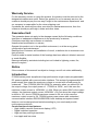
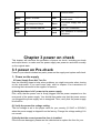
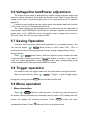
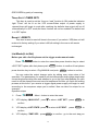
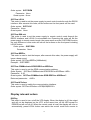
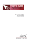
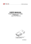
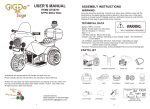
IT6900A series power supplies are high performance single-output programmable
DC power supplied with communication interface. This series of programmable DC
power supply can output the maximum voltage or current with a fixed power for
customers. Take IT6922A (60V/5A/100W) for example, when you select 60V for
the output voltage, the output power of IT6922A is 100W , so in this case the
maximum output current is 100W/60V = 1.66A. When you select 20V for the output
voltage, the maximum output current 100W/20V = 5A, but when the output voltage
is down to 10V, due to IT6922A maximum current is 5A, so in this case the
maximum output current is 5A. IT6900A series power comes with a standard
communication interface RS232/USB/GPIB, both desktop and system-based
features, can be designed and tested according to your needs and provide
multi-purpose solutions.
Convenient bench-top features:
• High visibility vacuum fluorescent display (VFD)
• Digital keyboard operation
• High accuracy and high resolution
• Low ripple and low noise
4
•
•
•
•
•
•
•
•
Intelligent fan control, energy conservation, noise reduction
Standard communication interface RS232/USB/GPIB
Can be monitored by computer software
Output voltage and current values accordance with procedure
Can use the knob to adjust the voltage and current
Can adjust the numbers steps using the cursor
Rich SCPI orders to facilitate the formation of intelligent test platform
Can set the output timer(0.1 ~ 99999.9 s)
V
60
Power
100%
40
20
1
2
3
4
5
I
IT6922A output curve figure
Chapter1 Inspection and Installation
Power supply is a high level safety equipment, there is a protected ground terminal.
Before Installation or operation, please read the safety signs and instructions in this
manual
1.1 Inspection
After received the power supply, follow these steps to check it:
1. Check for damage in the equipment during transport
If it is the frame, panel damaged, or abnormal working, ext. Please contact
immediately with our authorized dealer or service department. Do not return the
instrument before positive response has not been got.
2. Check the attachment
Make sure you receive the power and the following components at the same time, if
any missing, please contact your nearest dealer.
□ a power cord (in accordance with the standard voltage used in the region)
□ an operating manual.
□ a factory calibration report
5
□ a certificate
3. The power input requirements
there are two kinds of working voltage for the power supply: 110V and 220V, so
please pay attention to the working input voltage. There is a power cord which
matches with your local power in the attachment. If that does not match, please do
not hesitate to contact with our authorized dealer or service department.
AC input levels (select by change the power switch on the rear panel)
Option Opt.01: 220VAC ± 10%, 47 to 63 Hz
Option Opt.02: 110 VAC ± 10%, 47 to 63 Hz
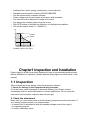
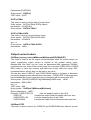
1.2 To Rack Mount the Instrument
You can mount the power supply in a standard 19-inch rack cabinet using the
IT-E151 rack mount kit.
Note: Remove the carrying handle and the two plastic ears before rack-mounting
the instrument. To remove the handle, grasp the handle by sides and pull
outwards and rotate it to a special position to let the arrow on the handle and
the arrow on the plastic ears be in opposite directions, then pull the handle
outward. After removing the handle, you can use a screwdriver to remove the
two plastic ears.
To rack mount a single instrument, order rack mount kit IT-E151
6
Side view of rack mounting a single instrument
To rack mount two instruments side-by-side, order rack mount kit IT-E151, you needn’t
to use the front cover panel.
1.3 The size of the power supply
1. IT6900A(
(IT6922A/IT6932A/IT6942A)
)power supply’s size
214.5mmW×88.2mmH×354.6mmD
*refer to the Dimensions below:
Unit:mm
IT6900A(
(IT6922A/IT6932A/IT6942A)
)power supply’s dimensions
2. IT6900A (IT6952A/IT6953A)
)is Lengthened, the size of it is:
214.5mmW×88.2mmH×445mmD
7
Chapter 2 Quick Start
This chapter introduces the front panel, the rear panel, key functions and VFD
display function of the power supply, make sure that you can quickly know the
appearance, instruction and the key function before you operate the power supply,
Help you make better use of this series of power supply.
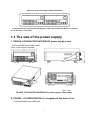
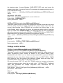
2.1 The front and rear panel description
1 VFD display
2 Rotary knob
3 Compound key, the local switch key and power switch
4 Number keys and ESC
5 Function keys
6 UP、DOWN, LEFT and RIGHT key, to move cursor
7 Output terminals
8
1
2
Cooling window
RS232 Communication cable interface
3
USB Communication cable interface
4
GPIB Communication cable interface
5
DVM input terminal,Remote measurement terminal and the output terminal
6
AC power socket(fuse contained)
Note: the AC power switch is at the bottom of the power supply.
2.2 Key introduction
11
22
33
Esc
V-set
I-set
44
55
66
0
Recall
Meter
77
88
99
·
Enter
On/Off
Key description, see the table below:
Keys
Name and the function
Compound key,co-work with OVP、Menu、Save、DVM、Trigger、
Shift
Lock
Local
Local switch key, switch from remote mode to local operation mode
9
Power
0-9
V-set
OVP
I-set
Menu
Recall
Save
Meter
DVM
Enter
Trigger
On/Off
Lock
Power on key
Numeric keys
Voltage set key, set the output voltage/over voltage protection point
for the power supply
Current set key, set the output current/menu function key, to set the
relevant Parameters for the power supply
Callback key to call up a set value of system parameters already
stored / storage key, to save system parameter settings
Meter key, to switch from value set panel and the actual output value
display / voltage meter function keys, to switch to the measure state
of the voltage meter
Enter key, to confirm the number entered and operation / trigger
button, which is used to trigger the List test.
Output on (off) keys, control power output state / keypad lock function
keys, used to lock the panel buttons
Left and right movement keys, used to set the value, to adjust the
cursor to the specified location
Up and down keys, used to select a item in the menu or increase
(decrease) the output voltage or current values
Cancel /return keys
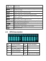
2.3
VFD Description
char
Function description
char
Function description
OFF
Output is off
Timer
Output on timer function is
ON
CV
CC
*
The power supply is in
Sense
constant voltage mode
The power supply is in
Ext
constant current mode
No
Adrs
10
No
No
(USB GPIB)light when the
address match or (RS232)
received order
The power supply is in
remote mode
The power supply has error
or fault
Meter
“Meter” on state
Rmt
Shift
Use compound keys
Error
OVP
OVP function state on
Prot
OVP OTP Protection
OCP
No
Lock
Key operation is locked by
Password
Chapter 3 power on check
This chapter will introduce the procedure of power on check, including pre-check
and output check, to make sure the power supply can power on and work normally
on the original state.
3.1 power on Pre-check
Power on pre-check includes two parts: power on the supply and system self check.
1.
.Power on the supply
If Power Supply Does Not Turn On
Use the following steps to help solve problems you might encounter when turning
on the instrument. If you need more help, refer to chapter 6 for instructions on
returning the instrument to the supplier for service.
(1)Verify that there is AC power to the power supply.
First, verify that the power cord is firmly plugged into the power receptacle on the
rear panel of the power supply. You should also make sure that the power source
you plugged the power supply into is energized. Then, verify that the power supply
is turned on.
(2) Verify the power-line voltage setting.
The line voltage is set to the proper value for your country (110VAC or 220VAC)
when the power supply is shipped from the factory. Change the voltage setting if it’s
not correct.
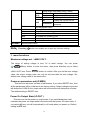
(3)Verify that the correct power-line fuse is installed.
If the fuse was damaged, please see the table below to replace the fuse for your
11
power supply.
Model
Fuse Specifications
(110VAC)
)
Fuse Specifications
(220VAC)
)
IT6922A
T4A
250V
T2A
250V
IT6932A
T6.3A
250V
T3.15A
250V
IT6942A
T12.5A 250V
T6.3A
250V
IT6952A
T10A
250V
IT6953A
T10A
250V
(4)How to exchange the fuse
Open the small plastic cover below the power supply input socket on the back
panel with a screwdriver, and you can see the fuse in it, please use the
specifications in line fuse.
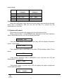
2. System self-check
After power on normally, the supply will enter self check test first.
About 1 second later,If the EEPROM was damaged or the latest operation
data in EEPROM was lost, the VFD will display as below:
EEPROM FAIL
If the last power status in EEPROM is lost, then VFD will display information
(about 1 S) as below:
SYST LOST
If the calibration data in EEPROM is lost, then VFD will display (about 1S) as
below:
CAL LOST
If the factory calibration data in EEPROM is lost, and then the VFD will
display(about 1 S) as below:
FACT
LOST
If the power supply is normal, then VFD will display the output voltage and
current status as below:
OFF
0.000V
0.0000A
12
Warning: The power supply is shipped from the factory with a power-line cord
that has a plug appropriate for your location. Your power supply is equipped
with a 3-wire grounding type power cord; the third conductor being the
ground. The power supply is grounded only when the power-line cord is
plugged into an appropriate receptacle. Do not operate your power supply
3.2 Output Checkout
The following procedures check to ensure that the power supply develops its rated
outputs and properly responds to operation from the front panel.
Voltage Output Checkout
The following steps verify basic voltage functions without load.
1) Turn on the power supply.
2) Set the current value(≥0.1A).
3) Enable the outputs
Press On/Off key to let the ON annunciator and the CV annunciator turn on
to light.
4) turn on Meter mode, press the METER key to light the button, the Meter
status Mark lights on the display is turned on.
Notice: if the voltage value flash, then the power supply is in Set mode, ‘‘Set
mode’’ means that the VFD display shows the setting output voltage and
current. Or the power supply is in Meter mode, ‘Meter mode” means that the
VFD display shows the actual output voltage and current.
5) Set the voltage for the power supply
Set different voltage values, check the voltage value displayed on the VFD is
close to the voltage value you set, and to check if the VFD displayed current
value is nearly zero.
6)Ensure that the voltage can be adjusted from zero to the full rated value
Current Output checkout
The following steps check basic current functions with a short across the power
supply’s output.
1) Turn on the power supply
2) Press On/Off key to ensure that the output is disabled. At the same time,
the OFF status mark is on the VFD.
3) Connect a short across(+) and (-) output terminals with an insulated test
lead, use a wire sufficient to handle the maximum current.
4) Adjust the voltage value to 1V.
5) Turn on the power output.
Press On/Off key to ensure the output is enabled, at the same time there is
CC status sign on the VFD.
6) Turn on METER function key.
Press METER key to light it, and the METER status sign is on the VFD.
7) Adjust the current value
Set some different current values, check whether the voltage value on VFD
13
is near 0v, and the current on it is close to the value you set.
8) Make sure that the current can be adjusted from 0 to full rated value.
9) Turn off the output of the power supply, and remove the short wire.
Chapter4 technical specification
This chapter will introduce the main technical parameters of IT6900A,such as
rated voltage/current/power and so on. Besides, we will introduce the working
environment and storage temperature.
14
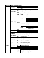
4.1 main technical parameters
Parameters
IT6922A
IT6932A
IT6942A
IT6952A
IT6953A
voltage
0 ~60V
0 ~60V
0~60V
0~60V
0~150V
current
0~5A
0~10A
0~15A
0~25A
0~10A
power
100W
200W
360W
600W
600W
voltage
≤0.01%+3mV
≤0.01%+5mV
≤0.01%+8mV
≤0.01%+15mV
≤0.01%+15mV
current
≤0.05%+2mA
≤0.05%+4mA
≤0.05%+6mA
≤0.1%+10mA
≤0.05%+10mA
voltage
≤0.01%+3mV
≤0.01%+5mV
≤0.01%+8mV
≤0.01%+15mV
≤0.01%+15mV
current
≤0.05%+2mA
≤0.05%+4mA
≤0.05%+6mA
≤0.1%+10mA
≤0.5%+10mA
voltage
1mV
1mV
1mV
1mV
1mV
current
0.1mA
0.1mA
0.1mA
0.1mA
0.1mA
voltage
1mV
1mV
1mV
1mV
1mV
resolution
current
0.1mA
0.1mA
0.1mA(<10A)
0.1mA(<10A)
1mA(>10A)
1mA(>10A)
Setup accuracy
voltage
≤0.03%+5mV
≤0.03%+5mV
≤0.03%+5mV
≤0.03%+5mV
≤0.03%+20mV
current
≤0.1%+5mA
≤0.1%+10mA
≤0.1%+15mA
≤0.1%+25mA
≤0.1%+25mA
voltage
≤0.03%+5mV
≤0.03%+5mV
≤0.03%+5mV
≤0.03%+5mV
≤0.03%+20mV
current
≤0.1%+5mA
≤0.1%+10mA
≤0.1%+15mA
≤0.1%+25mA
≤0.1%+25mA
Ripple
voltage
≤5mVp-p
≤8mVp-p
≤15mVp-p
≤20mVp-p
≤50mVp-p
(20Hz ~20MHz)
current
≤5mArms
≤6mArms
≤8mArms
≤15mArms
≤15mArms
Rated values
( 0 °C~40 °C)
Load regulation
±(%
%of
output+offset)
Line regulation
±(%
%of
output+offset)
Setup
resolution
Readback
0.1mA
(within
twelve months)
)
(25°C±5°C)
±(%
%of
output+offset)
Read back
resolution
(W)
)
(25°C±5°C)
±(%
%of
output+offset)
10HZ/S
Sample rate
Dimension
(mm)
)
weight
214.5mmW×88.2mmH×354.6mmD
214.5mmW×88.2mmH×445mmD
7.7Kg
15Kg
4.2 supplementary characteristic
State register capacity:
:9×8group operation state
calibrationfrequency:1time/year
Radiating mode
Fans
15
suggested
Operation temperature
0 to 40 °C
Storage temperature
-20 to 70 °C.
Humidity
Max humidity: 80%
Chapter5 Basic operation
This chapter has several subdivisions:
Local/remote mode
Voltage setup
Current setup
on/off operation
Setup value/actual value
Voltage/current/power adjustment
Saving operation
Trigger operation
Menu operation
OVP protection function
Key lock function
DVM measure function
5.1 Local/Remote Mode
Local button can enable you switch mode from remote to local mode.
After you power on the power supply, unit will default in local mode, all the
buttons can be used in this mode. While in remote mode, you can’t operate through
front panel directly. Local and remote mode can be controlled through PC. In
addition, the mode changing will not influence the output parameters.
5.2 Voltage Setup
You can set voltage within the range of rated voltage value. When you press
V-set
button, the button will be lit. This indicates that you can set voltage. There
are three ways to set output voltage through front panel.
The first way: press V-set ,adjust cursor location through
16
button,
pressing
and
will enable you to adjust the setting voltage value.
The second way: press V-set , adjust cursor location through
adjust rotary knob
button,
to change the setting voltage value.
The third way: press
V-set
button and number key(
0
to
9
) to set
voltage value
5.3 Current Setup
You can set current within the range of rated current value. When you press
I-set
button, the button will be lit. This indicates that you can set current. There
are three ways to set output current through front panel.
The first way: press I-set
and
push
,adjust cursor location through
button,
will enable you to adjust the setting current value.
The second way: press I-set
adjust rotary knob
,adjust cursor location through
button,
to change the setting current value.
The third way: press
I-set
button and number key(
0
to
9
) to set
current value
5.4 On/Off Operation
On/Off
button is used to control the output state of power supply. When
button is lit, this indicates the output is in on mode. When output is open,
the working state indicator light(CV/CC) will be lit.
Note: make sure you have connected power supply well, then press On/Off
button.
On/Off
5.5 Setup value/Actual value
You can switch the display between setting value and actual value by
pressing Meter
button. When this button is lit, screen displays actual output value
and the indicator light “meter” will be lit on the VFD board. In other words, when the
button is not lit, the front panel displays setting value.
17
5.6 Voltage/Current/Power adjustment
The output current value is determined by output voltage of power supply and
electronic load’s resistance. Only when the actual current value is lower than the
setting current value, can power supply work in CV mode and the will CV indicator
light be lit.
If output current is higher than the setting value, then power supply will function
in CC mode. And the CC indicator light will be lit.
The output voltage and current value are also influenced by the upper limit of
output power. Take IT6932A(60V/10A/200W) for example, suppose you set the max
power value to be 200W,then when the setting output voltage and current is
25V/10A,in fact, the unit can only output 25V/8A.
5.7 Saving Operation
Customer can save some often-used parameters in nonvolatile memory. You
can use the button
+
Recall
(Save) button or SCPI order *SAV、*RCL to
achieve this function. Saving parameters include: setting voltage/setting current
Saving method:
Press
+ Recall (save) button, and then input the group number you want
to save through number key board. Press enter button to confirm. If you want to
recall the saved parameters, press Recall button and corresponding group
number(number1-9).At last press enter button to confirm.
5.8 Trigger operation
You need to select the trigger mode from the menu before using this function.
After you edit a list file, press
+
Enter
(Trigger)to give a trigger signal.
During the running process, Enter button will be lit all the time.
5.9 Menu operation
1 Menu description
Press
+
I-set
(Menu) to enter the menu. You will see a optional items on
the screen, through direction keys and rotary knob to upturn VFD display, then the
screen will display the following functions .Press
corresponding items. Press
ESC
Enter
button will enter
button will return to previous menu.
18
MAX VOLT Set the max output voltage
SYST SET
Reset Power is restored to factory setting
P-MEN
Set the power-on state as the last power off
(RESET)
)
Keep
state
Enable the power-on output state to be off
OFF
mode
P-OUT (OFF)
Set the power-on output state to be the last
Keep
power-off output state
Address can be set within
ADDR
GPIB
0-30
4800
9600
BAUD
19200
38400
57600
COMM (GPIB)
115200
RS232
NONE 8BIT
NONE 8BIT
EVEN 8BIT
ODD 8BIT
SIGNAL
MODE
MUX
ADDR. Address can be
set within 0-30
USB
BEEP (ON)
KNOB (ON)
TRIG (MANUAL)
MEM (GROUP1)
BUS
Close the key sound
Open the key sound
Lock the rotary knob function
Unlock the rotary knob function
Local keyboard trigger
External trigger
GRP1-8
Save and recall operation
OFF
ON
LOCK
ON
MANU
Close the timer function
Open the timer operation, the time can be
ON
set within 0.1-99999.9s
NO
keep the original setting
YES
restore the factory setting
Quit the menu setting
OFF
Close list test function
ON
Open list test function
Recall the saved list file(FILE0-FILE9)
)
TIME
SEC
second
(SEC)
MIN
minute
VSET
Setup the single step voltage
ISET
Setup the single step current
OFF
TIMER SET
RESET
EXIT
LIST SET
LIST STATE
LIST LOAD
LIST EDIT
19
Setup single step delay time(0.1-9999)
NEXT
YES
continue the edit of next step
(YES)
NO
End up the list file edit
REPET 1-65535
Set the cycle time of list file
NO
Unsave the current list file
SAVE
Save the list file to appointed
FILE0-FILE9
document
EXIT
quit the system menu
POWER INFO MODEL
unit model
VER
the software version
SN-1
the first six number of SN
SN-2
the middle six number of SN
SN-3
the last six number of SN
EXIT
Quit the information menu
EXIT MENU Quit the main menu
SEC
Note:
:Pressing
ESC
button can enable you to quit any function setting.
2. menu functions
Maximum voltage set(>MAX VOLT)
The range of setting voltage is from 0V to rated voltage. You can press
+ I-set
(Menu) button to enter the menu, then press direction key to select
>MAX VOLT item. Press
Enter
button to confirm. After you set the max voltage
value, the output voltage value can only be set less than the max voltage. Our
default max voltage value is the rated value.
Power-on parameters set(>P-MEN)
This item can set power on state of parameters. If you select RESET item, then
all the parameters will be initialized to the factory setting. Output voltage and current
will always be 0V/0A.Or the output value will be the same with last power off state.
The default setting is RESET item.
Power On Output State(>P-OUT )
This item can set the power on output state. If you select keep item, that
indicates the power on output state is the same with last power off output state. If
you select off item, unit will automatically in off mode when you power on. Default
setting is OFF item.
20
Communication (>COMM )
Our unit has provided three standard communication interfaces:
RS232/USB/GPIB.In this option, you can select the communication interface
according to your demands. The range of GPIB address is 0-30. Besides, we have
multi-baudrate to be chosen in RS232
mode---4800,9600,19200,38400,57600,11.52K.Data bit is 8,Check digit have three
choices: NONE,ODD,EVEN.Before you begin to carry out communication,please
make sure the configure in our unit agrees with PC configure.
Key Sound Set(>BEEP ON)
This item can set the key sound state.If in on mode,then key sound will be
there when you press buttons.If in off mode,the beeper will not make a sound.The
default set is in on mode.
Rotary Knob Set(
(>KNOB )
This item is used to set rotary knob state.In on mode,you can use this rotary
knob to set the output value and overturn the menu items.In lock mode,this knob
can’t be used.The default setting is in on mode.
Trigger mode(
(>TRIG )
Before you running a list file,you need a trigger signal.Thus you must set the
trigger mode firstly,in keyboard trigger mode or in external trigger mode.In MANU
trigger mode,press
+ Enter button can generate a trigger signal.In BUS
trigger mode,you can only through sending orders to trigger.The default set is
MANU option.
Group Set(
(MEM GROUP)
)
Power supply can save some often-used parameters in a nonvolatile
memory(capacity is 9*8 groups).This function can make the operations more
convenient. Customer can save and recall parameters quickly.
GRP1:This indicates saving power supply parameters in 1-9 groups.Press
+
Recall
(Save) and the group number(1-9) can save the parameters in corresponding
groups.
GRP2:This indicates saving the parameters in 10-18 groups.Press +
Recall
(Save)+saved group number(1-9)can save related parameters.Note that
the current number “1” represents parameters are saved in 10th groups.Number “2”
represents the parameters are saved in 11th groups.
21
GRP3-GRP8 by parity of reasoning.
Timer Set(
(>TIMER SET)
)
This item is used to set the “time on- load” function.In ON mode,the indicator
light “Timer” will be lit on the VFD screen.When output of power supply is
opened,timer will begin to work,after reaching the definite time,output will be off
automatically.If in OFF mode,the timer function will not be enabled.The default set
is in OFF option.
Reset(
(>RESET)
)
This item is used to reset all items in the menu.If you select >YES,then unit will
restored to factory setting.If you select >NO,all setting in the menu will remain
unchanged.
List Mode(>List Set)
Before you edit a list file,please set the trigger mode:manual mode.
Press
+ I-set
button to enter the menu,then press direction key to select
Enter
>SYST SET option,after that please push
button to confirm.At last please
press direction key to select >Trig MANUAL and push
Enter
button to confirm.
You can make the output change order by editing every step value of list
operation. The parameters you need to edit includes:single-step voltage,single-step
current,single-step delay time and whether to go on the next step.Besides,you also
need to set the repeat times and save list sequence file.After you finish the editing
process,at this time if you receive a trigger signal,power supply will begin to work
according to the sequence steps you’ve edited. Now we take five steps for an
example:
Operation steps:
1) Press
+ I-set
(Menu)button to enter the menu
2) VFD display >MAX VOLT,press
to select >LIST SET,press
Enter
to
to select >LIST EDIT, press
Enter
to
confirm
3) VFD display >LIST STATE,press
confirm
4) VFD display >TIME SEC,press Enter
22
to confirm,go to the next step,you
can also through
button to select >TIME MIN time unit,press
Enter
to
confirm.
0
5) VFD display >VSET 0.000,press number key
Enter
knob to set voltage,after that press
6) VFD display ISET 0.0000, press number key
the single-step current, press
Enter
Enter
8) VFD display NEXT >YES,press
9
or through rotary
to confirm.
0
9
to
or rotary knob to set
to confirm.
7) VFD display SET 0.1,press number key
single-step delay time,press
to
0
to
9
or rotary knob to set
to confirm.
Enter
to confirm.
9) Repeat the steps from 5) to 8) and set the four steps’ voltage/current and delay
time separately. When screen display NEXT>YES in the fourth step edit
process,please press
to select NEXT >NO,press
0
10) VFD display REPET 1,
,press number key
repeat times,press
Enter
to
9
Enter
to confirm.
or rotary knob to set the
to confirm.
11) VFD display SAVE >NO,press
Enter
to confirm,in this circumstance,the
list file is not saved but can run for one time,or you can press
button to
select >SAVE FILE0,saving the list test file in FILE0~FILE9,press
Enter
to
confirm.You can recall the file in the following utilization.
12) If you do not save the list test file,VFD will display LIST EDIT;if you select to
save the test file,VFD will display SAVE DONE for three seconds,and then
display LIST EDITL.
13) Press
to select >LIST STATE item,press
14) VFD display LIST >OFF, press
confirm.Now
Enter
Enter
to confirm.
to select >LIST >ON, press Enter
to
button will be lit.This indicates that list operation
function has been opened.
,pressing
15) VFD display >LIST STATE,
23
Esc
button can quit the operation.
16) Press On/Off
button to open the output,press
+ Enter (Trigger)to give
a trigger signal.
17) If you have edited several list files,you can select LIST LOAD item to recall the
file you need.And then press
Esc
to quit this operation.Press On/Off
to open the output.Now you only need to press
button
+ Enter (Trigger) to give a
trigger signal,the list file can be ran.
18) In LIST mode,voltage set and current set button can’t be used,In LIST STATE
item,choose LIST>OFF will enable you to quit list mode.
5.10 OVP Function
IT6900A series power supply provide OVP function,press
+ V-set
button
can enable you to set the over voltage protection value.Over voltage may caused
by internal defect or customer’s incorrect operation(such as output voltage rising),or
external voltage too high.Once power supply is protected(OVP),the output will be
off immediately and “OVP” indicator light will be lit,the VFD display “OVER VOLT”。
Avoid external voltage that across the output terminals exceeding the 120% of
rated voltage or it will damage out power supply!
When power supply in OVP state,please check the external factors first, after
you exclude the external factors, press ON/OFF button to open output again.If in
communication state originally, you should by sending order OUTP ON order to
open output.
5.11 Key Lock
Press
+ On/Off (Lock)button to set the key lock state.If keyboard has been
locked,the indicator light LOCK will display on the VFD screen.In addition,when key
board are lock,all butttons can’t be used but ON/OFF 、 Meter buton 、 shift
button.Press this button once again will relieve key lock function.
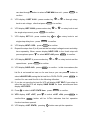
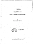
5.12 Rear pins function
-
+
s+
s-
v+ v-
24
+,- :output terminals,the same with front pannel output terminals ;
S+,S- :remote sense pins.Disconnect the wires between “+,-”pins if you want to
use remote sense function.Then lead a wire from S+,S- pins and
connect to the under test objects.
V+,V-:the output interface of a four semi-digital voltmeter.
IT6900A series power supply has four semi-digital voltmeter.This DVM can
measure 0.001V to 61.000V voltage.Press
+ Meter (DVM)button can enable
the measured value display on the VFD screen.Press any key to quit the display of
this value.
Chapter6 Remote Operation Mode
IT6900A series power supply three standard communication interface: RS232, USB,
GPIB, the user can choose to any one of them to implement a communication with
the computer.
6.1 RS232 interface
There is a DB9 connector at the rear of the power supply, when connect to
computer, you need to connect a cable with COM port on both side;
active connection, you need to set the front panel composite key
+
I-set
configuration settings the same as computer configuration settings.
interface can be used to program all of the SCPI orders.
key
RS-232
Note : The RS232 settings must match the settings in front panel system
+ I-set
information. If any change, please press
key。
RS-232 data format
RS-232 data is a 10-bit words which has a start bit and a stop bit. The start bit
and stop bit can’t be edited. However, you can select the parity items with
+ I-set
key on the front panel.
25
Parity options are stored in nonvolatile memory
Baud Rate
The front panel
+ I-set
button allows the user to select a baud rate which is
stored in the non-volatile memory: 4,800,960,019,200 3,840,057,600,115,200
RS-232 connection cable
Use a RS232 cable with DB-9 interface, RS-232 serial port can connect with the
controller (eg PC). Do not use blank Modem cable. Table 2-2 shows the plug pins.
If your computer is using a RS-232 interface with DB-25 connector, you need a
adapter cable with a DB-25 connector at one end and the other side is a DB-9(not
blank modem cable)
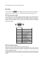
RS-232 plug pins
Pin number Description
1
No connection
2
TXD, transfer date
3
RXD, receive data
4
No connection
5
GND, ground
6
No connection
7
CTS, clear transfer
8
RTS, ready to transfer
9
No connection
RS-232 Troubleshooting:
If there is RS-232 connection problem, check the following:
Computer and power supply must configure the same baud rate, parity, data bits
and flow control options. Note that the power configuration as a start bit and a stop
bit (these values are fixed).
As described before in RS-232 connector, you must use the correct interface cable
or adapter. Note that even if the cable has the right plug, the internal wiring may be
wrong.
26
Interface cable must be connected to the correct serial port on the computer (COM1,
COM2, etc.).
Communication Settings
Before communication, you should first make the following parameters of power
supply and PC matches.
Baud Rate: 9600 (4800,9600,19200,38400,57600,115200). You can enter the
system menu from the front panel, and then set the baud rate.
Data bits: 8
Stop Bits: 1
calibration (none, even, odd)
EVEN
8 data bits, have even parity
ODD
8 data bits have odd parity
NONE
8 data bits, no parity
Local Address: (0 ~ 31, the factory default setting is 0)
Parity=None
Start Bit
8 Data Bits
Stop Bit
6.2 USB interface
Use a Cable with two USB port to connect the power and the computer. All power
functions can be programmed via USB.
The USB488 interface functions of the power supply described as below:
interface is 488.2 USB488 interface.
Interface Receiver REN_CONTROL, GO_TO_LOCAL, and LOCAL_LOCKOUT
request.
Interface receive MsgID = TRIGGER USBTMC order information, and will pass
TRIGGER order to the functional layer.
Power USB488 device functions described as follows:
devices can read all of the mandatory SCPI orders.
device is SR1 enabled.
device is RL1 enabled.
device is DT1 enabled.
6.3 GPIB interface
First, Connect the GPIB interface on the power supply and the GPIB card on
computer via IEEE488 bus, must be full access and tighten the screws. Then set
the address, the address range of the power : 0 to 30, can set by the function key
on the front panel,
press the
+ I-set
find the GPIB address setting by
key to enter the system menu function,
▼
button, type the address,
confirm. GPIB address is stored in nonvolatile memory line.
27
Enter
key to
Note: Forbidden to connect DB9 connector in power supply directly with PC or other
RS232 port.
Chapter7 Communication protocal
7.1 SCPI order table
IEEE488.2common orders
"*CLS"
"*ESE"
"*ESE?"
"*ESR?",
"*IDN?",
"*OPC",
"*OPC?",
"*PSC",
"*PSC?",
"*RST",
"*SRE",
"*SRE?",
"*STB?",
"*TRG",
"*SAV ",
"*RCL",
"*TST?",
"STATus:QUEStionable[:EVENt]?",
"STATus:QUEStionable:ENABle",
"STATus:QUEStionable:ENABle?"
"STATus:QUEStionable:CONDition?"
System orders
"SYSTem:VERSion?",
"SYSTem:ERRor?",
"SYSTem:REMote",
28
"SYSTem:LOCal",
"SYSTem:RWLock",
"SYSTem:BEEPer",
"SYSTem:COMMunicate:GPIB:RDEVice:ADDRess",
"SYSTem:COMMunicate:GPIB:RDEVice:ADDRess?",
"SYSTem:INTerface",
Display relevant orders
"DISPlay[:WINDow][:STATe]",
"DISPlay[:WINDow][:STATe]?",
"DISPlay[:WINDow]:TEXT[:DATA]",
"DISPlay[:WINDow]:TEXT[:DATA]?",
"DISPlay[:WINDow]:TEXT:CLEar"
Trigger orders
"TRIGger[:IMMediate]",
"TRIGger:SOURce",
"TRIGger:SOURce?"
Output orders
"[SOURce:]OUTPut[:STATe]",
"[SOURce:]OUTPut[:STATe]?",
"[SOURce:]OUTPut:TIMer[:STATe]",
"[SOURce:]OUTPut:TIMer[:STATe]?",
"[SOURce:]OUTPut:TIMer",
"[SOURce:]OUTPut:TIMer?",
Current control orders
"[SOURce:]CURRent[:LEVel][:IMMediate][:AMPLitude]",
"[SOURce:]CURRent[:LEVel][:IMMediate][:AMPLitude]?",
"[SOURce:]CURRent[:LEVel]:UP[:IMMediate][:AMPLitude]",
"[SOURce:]CURRent[:LEVel]:DOWN[:IMMediate][:AMPLitude]",
"[SOURce:]CURRent[:LEVel][:IMMediate]:STEP[:INCRement]",
"[SOURce:]CURRent[:LEVel][:IMMediate]:STEP[:INCRement]?",
"[SOURce:]CURRent[:LEVel]:TRIGgered[:IMMediate][:INCRement]",
"[SOURce:]CURRent[:LEVel]:TRIGgered[:IMMediate][:INCRement]?",
Voltage control orders
"[SOURce:]VOLTage[:LEVel][:IMMediate][:AMPLitude]",
"[SOURce:]VOLTage[:LEVel][:IMMediate][:AMPLitude]?",
"[SOURce:]VOLTage[:LEVel]:UP[:IMMediate][:AMPLitude]",
"[SOURce:]VOLTage[:LEVel]:DOWN[:IMMediate][:AMPLitude]",
"[SOURce:]VOLTage[:LEVel][:IMMediate]:STEP[:INCRement]",
"[SOURce:]VOLTage[:LEVel][:IMMediate]:STEP[:INCRement]?",
"[SOURce:]VOLTage[:LEVel]:TRIGgered[:AMPLitude]",
29
"[SOURce:]VOLTage[:LEVel]:TRIGgered[:AMPLitude]?",
"[SOURce:]VOLTage:PROTection[:LEVel]",
"[SOURce:]VOLTage:PROTection[:LEVel]?",
"[SOURce:]VOLTage:PROTection:STATe",
"[SOURce:]VOLTage:PROTection:STATe?",
"[SOURce:]VOLTage:PROTection:TRIPed?",
"[SOURce:]VOLTage:PROTection:CLEar",
"[SOURce:]VOLTage:LIMIT[:LEVel]",
"[SOURce:]VOLTage:LIMIT[:LEVel]?",
Compound control orders
"[SOURce:]APPLy",
"[SOURce:]APPLy?",
Calibration orders
"CALibrate:SECure[:STATe]",
"CALibrate:SECure[:STATe]?",
"CALibrate:INITital",
"CALibrate:SAVe",
"CALibrate:VOLTage:LEVel",
"CALibrate:VOLTage[:DATA]",
"CALibrate:CURRent:LEVel",
"CALibrate:CURRent[:DATA]",
"CALibrate:DVM:LEVel",
"CALibrate:DVM[:DATA]",
"CALibrate:STRing",
"CALibrate:STRing?",
Measure orders
"MEASure[:SCALar]:CURRent[:DC]?",
"FETCh:CURRent[:DC]?",
"MEASure[:SCALar][:VOLTage][:DC]?",
"FETCh[:VOLTage][:DC]?",
"MEASure[:SCALar]:POWer[:DC]?",
"FETCh:POWer[:DC]?",
"MEASure[:SCALar]:DVM[:DC]?",
"FETCh:DVM[:DC]?",
"MEASure[:SCALar]:STATus",
List operation orders
"[SOURce:]LIST:FUNCtion",
"[SOURce:]LIST:FUNCtion?",
"[SOURce:]LIST:LOAD[:IMMediate]",
"[SOURce:]LIST:LOAD[:IMMediate]?",
30
"[SOURce:]LIST:VOLTage",
"[SOURce:]LIST:VOLTage?",
"[SOURce:]LIST:CURRent",
"[SOURce:]LIST:CURRent?",
"[SOURce:]LIST:TIMEr",
"[SOURce:]LIST:TIMEr?",
"[SOURce:]LIST:SAVE",
"[SOURce:]LIST:REPet",
"[SOURce:]LIST:REPet?"
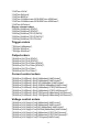
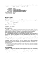
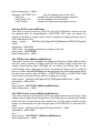
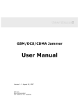
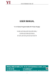
7.2 SCPI status register
IT6900A series power records variable instrument status via three kinds of status
register, the three kinds of registers are standard event register, query status
register and status bytes register. Status byte register records the information of
other status registers. The below picture will give you more detailed information:
31
Questionable Status
Enable Register
Event Register
VOLTAGE
0
CURRENT
1
Output Buffer
not used
not used
TEMPERATURE
4
not used
not used
not used
OR
+
not used
OVERVOLTAGE
9
OVERCURRENT
10
Status Byte
not used
not used
Summary Register
not used
not used
not used
not used
not used
not used
STAT:QUES?
STAT:QUES:ENAB<value>
QUES
3
STAT:QUES:ENAB?
MAV
4
ESB
5
RQS
6
OPER
7
Standard Event
Enable Register
Event Register
Operation Complete
OPC
Enable Register
0
OR
+
Serial Poll
*SRE<value>
*STB?
*SRE?
not used
Query Error
QYE
2
Device Dependent Error
DDE
3
Execution Error
EXE
4
Command Error
CME
5
+
OR
not used
Power On
PON
7
*ESR?
*ESE<value>
*ESE?
Operate Event
Enable Register
Event Register
CAL
ON/OFF
WTG
not used
not used
not used
not used
not used
0
1
2
+
OR
Event register is read only register, used to store the implementation status of the
32
power, the data used in the event register latches in the form, once the data is
stored, subsequent data will be completely ignored. Even can’t changed by
re-setting order (* RST) or equipment restart.
but if query the data in event register or send clear order *CLS(clear status), the
event register will be automatically cleared. The main content which the standard
event register records is:
whether power output is turned on, order syntax errors, order execution errors,
self-test or calibration errors, query errors and so on.
Bit
Decimal
Value
1
0
OPC
1
2
Not
Used
QYE
4
3
DDE
8
4
EXE
16
5
CME
32
6
Not
Used
PON
0
7
0
Definition
Operation Complete. All orders prior to and including
an *OPC order have been executed.
Always set to 0.
Query Error. The power supply tried to read the
output buffer but it was empty. Or, new order line
was received before a previous query had been read.
Or, both the input and output buffers are full.
Device Error. A self-test or calibration error occurred
(see error numbers 601 through 750 in chapter 5).
Execution Error. An execution error occurred (see
error numbers -211 through -224 in chapter 5).
Order Error. A order syntax error occurred (see error
numbers -101 through -178 in chapter 5).
Always set to 0.
128
Power On. Power has been turned off and on since
the
last time the event register was read or cleared
Query status register provide some information of the power, such as over voltage,
over temperature, over current, you can also monitor the change of the constant
current and voltage status via the register, for example, data bit 0 is the constant
current mode of the power supply, data bit 1 is constant voltage mode of the power
supply, and so on.
Bit
0
Voltage
Decimal
Value
1
1
Current
2
Definition
The power supply is/was in the constant
current mode.
The power supply is/was in the constant
33
2-3
4
5-8
9
10
Not used
Over
temperature
Not used
Over voltage
Over Current
0
16
voltage mode.
Always set to 0.
The fan has a fault condition.
Always set to 0.
The overvoltage protection circuit has tripped.
The over current protection circuit has
tripped.
11-15 Not used
0
Always set to 0.
Status byte register records the information of other registers. The query data is
temporally stored in the output buffer of the power supply, and feedback to
customer through BIT4 bit. The data bits in Status byte group will not be latched,
when the information in event register is changed, the correspo0nding bit in status
byte register will subsequently be changed.
Bit
0
512
1024
0-2
3
Not used
QUES
Decimal
Value
0
8
4
MAV
16
5
ESB
32
6
RQS
64
7
Not used
0
Definition
Always set to 0.
One or more bits are set in the questionable
status register (bits must be “enabled” in the
enable register).
Data is available in the power supply output
buffer.
One or more bits are set in the standard event
register (bits must be “enabled” in the enable
register).
The power supply is requesting service (serial
poll).
Always set to 0.
7.3 SCPI order description
IEEE488.2 common orders
*CLS
This order can clean the register as follows::
Standard event status register
Quest condition register
Operation event register
Status byte register
Error code
Order syntax:*CLS
Parameter:None
34
*ESE
This order can set the parameter of standard event enable register. Setting
parameter can determine which bit value of standard event register is 1 and the
byte will enable ESB of status byte register is 1.
Order syntax:*ESE <NR1>
Parameter:0~255
Reset value:Consult *PSC order
Example:*ESE 128
?
Quest syntax:*ESE?
Return parameter:<NR1>
Reference order:*ESR?
? *PSC *STB?
?
*ESR?
This order can read the value of standard event status register. After executing this
order, standard event status register is reset. Bit definition of standard event status
register is as the same as the standard event status enable register
?
Quest syntax:*ESR?
Parameter:None
Return parameter:<NR1>
Reference order: *CLS *ESE
*ESE?
? *OPC
*IDN?
This order can read information about power supply. The parameter it returns
contains 4 segments divided by comma.
?
Quest syntax:*IDN?
Parameter:None
Return parameter:<AARD>
For example:ITECH Ltd,IT6922A,0123456789AF,1.00
*OPC
When all orders before this order are executed, OPC is 1 for the standard event
status register.
Sending query order will return 1 to output buffer.
Order syntax:*OPC
Parameter:None
Quest syntax:*OPC?
?
Return parameter:<NR1>
*PSC
This order control if power supply send a query or not when it is reset.
1 OR ON:When power supply is reset, operation event enable register, query event
enable register and standard event status register are all reset.
0 OR OFF:The data of status byte register, operation event enable register, quest
event enable register and standard event status enable register is
stored in nonvolatile register, and is recalled when power supply is
35
reset.
Order syntax:*PSC <bool>
Parameter: 0|1|ON|OFF
Quest syntax:*PSC?
?
Return parameter:0|1
Reference order:*ESE *SRE STAT:OPER:ENAB STAT:QUES:ENAB
*RST
This order reset the power supply to default setting.
CURR
CURR:STEP
CURR:TRIG
DISP ON
OUTP OFF
TRIG:SOUR BUS
VOLT:STEP
VOLT:TRIG
VOLT:PROT
ON
Order syntax:*RST>
Parameter:None
CURR:PROT
VOLT 0V
VOLT:PROT:STAT
*SRE<enabled value>
This order can set the parameter of standard event register. When query status bit
enable register, the power will return a decimal number, this number is the binary
weighted of enable register.
Order syntax:*SRE <NRf>
Parameter:0~255
Reset value:Consult *PSC order
Example:*SRE 128
Quest syntax: *SRE?
?
Return parameter:<NR1>
Reference Order:*ESE *ESR?
? *PSC *STB?
?
*STB?
This order can read the data from status byte register.
This order is similar to a statistics of series, but the equivalent of another instrument
orders, it returns the value the same as series statistics, but after this order is
executed, the bit 6 value of status byte register is cleared, while the status bit will
not be cleared when system statistics implemented.
Quest syntax:*STB?
?
Parameter:None
Return parameter:<NR1>
Reference order: *CLS *ESE *ESR
*TRG
When the trigger mode of the power supply is BUS order trigger mode, the order
will Generates a trigger signal.
The function is the same as TRIGger[:IMMediate]
36
Order syntax: *TRG
Parameter: none
Reference order:TRIG
TRIG:SOUR
*SAV
This order can save the parameters of power supply to register. These parameter
contains:
CURR
CURR:STEP
CURR:TRIG
CURR:PROT
DISP
OUTP
TRIG:SOUR
VOLT
VOLT:STEP
VOLT:TRIG
VOLT:PROT
VOLT:PROT:STAT
Order syntax:*SAV<NRf>
Parameter:1~72
Example:*SAV 3
Reference order:*RCL
*RCL
This order can recall the parameter you saved before from the register.
Order syntax:*RCL<NRf>
Parameter:1~72
Example:*RCL 3
Reference order:*SAV
STATus:QUEStionable[:EVENt]?
This order can read the parameter from quest event register. the power supply will
return a decimal number which is corresponding to the binary weighted sum of each
bit of the register,, these bits have been latched. After executing, quest event
register is reset.
Quest syntax:STATus:QUEStionable[:EVENt]?
Parameter:None
Return parameter:<NR1>
Reference order: STATus:QUEStionable:ENABle
STATus:QUEStionable:CONDition?
This order can be used to read the value of query condition register and to get the
status of the power, if it is CC or CV,. The power supply will return a decimal number
corresponding to the binary-weighted sum of each bit of the register. These bits are
not latched. If 0 is returned, then the output status of the power is OFF or uncertain.
If 1 is returned, then the status is CC mode, if 2 is returned, then the status is CV. If
3 is returned, then there is error occurred.
Quest syntax:STATus:QUEStionable: CONDition?
Parameter:None
Return parameter:<NR1>
STATus:QUEStionable:ENABle<enabled value>
This order can set the parameter of quest event enable register. The power supply
37
will return a decimal number which is the binary-weighted sum of the enable
register.
Order syntax:STATus:QUEStionable:ENABle <NRf>
Parameter:0~255
Reset value:Consult *PSC order
Example:STATus:QUEStionable:ENABle 16
Quest syntax:STATus:QUEStionable:ENABle?
?
Return parameter:<NR1>
Reference order:*PSC
System order
SYSTem:VERSion?
This order can query the version of the SCPI order. Returned value is a string like
“YYYY.V”,
In which the YYYY is the year of this version, V is the version.
Order syntax:SYST:VERS?
Parameter:None
Return parameter:<NR2>
Example:1.00,1991.1
SYSTem:ERRor?
This order is used to query the error information of the power supply. When the
error LED lights on the front panel, it tells us that there is one or more hardware or
order syntax error happened. There are at most 20 groups of error message.
Send the order once will read one error message from the error queue.
1. Error messages follow the FIFO (first-in-first-out) principle. The first error will be
returned first. when you read all the error tips information in the error queue. The
ERROR led will turn off. When error occur the buzzer of the power supply will
beep once.
2. If more than 20 errors occurred, the last one stored in the queue will be replaced
by “-350”, Meaning "too many mistakes.". If the error messages in the error
message queue are not read out, the error following will not be saved to the
queue. If there is no error message, when read error information, it will return “+0”,
meaning “no error”.
3. If turn off the power supply or send “CLS(clear status) order, the error messages
in the error queue will be cleared. *RST order will not clear the error messages
in the error queue.
SYSTem:REMote
This order is used to set the power supply to remote control mode through the
RS232 interface. Except for the Local key on the front panel, other keys are locked
and can’t be used. Send or receive orders without first sending the order to
configure the remote control may cause unpredictable results.
38
Order syntax:SYST:REM
Parameter:None
Quest syntax:None
SYSTem:LOCal
This order is used to set the power supply to panel control mode through the RS232
interface. After execute this order, all the buttons on the front panel can be used.
Order syntax:SYST:LOC
Parameter:None
Quest syntax:None
SYSTem:RWLock
This order is used to set the power supply to remote control mode through the
RS232 interface, and LOCAL is not available too. Executing this order will set the
power supply to remote control mode ,the same result as order SYST:REM function,
the only difference is this order will lock all the buttons on the front panel including
LOCAL button.
Order syntax:SYST:RWL
Parameter:None
SYSTem:BEEPer
This order is used to test the beeper, after execute this order, the power supply will
issue a beep sound.
Order syntax: SYSTem:BEEPer[:IMMediate]
Example:SYST:BEEP
SYSTem:COMMunicate:GPIB:RDEVice:ADDRess
This order is used to set the GPIB communication address.
Order Syntax: SYSTem:COMMunicate:GPIB:RDEVice:ADDRess <NR1>
Parameter:0-30
Quest syntax:SYSTem:COMMunicate:GPIB:RDEVice:ADDRess?
Returned parameter: <NR1>
SYSTem:INTerface
This order is used to switch the communication interface.
Order syntax: SYSTem:INTerface <GPIB|USB|RS232>
Display relevant orders
DISPlay
This order is used to turn on/off the VFD display. When the display is off, the output
and will not be displayed on the VFD, at the same time, all the LED except for
ERROR led will not be off. When the control mode is local, the display will turn on
automatically, press LOCAL button can switch the control mode from remote to
39
local.
Order syntax:DISPlay[:WINDow][:STATe] <bool>
Parameter : 0|1|OFF|ON
Example:DISPlay 1
quest syntax:DISPlay?
Returned parameter:0|1
DISPlay:TEXT< Reference value>
This order is used to display a text on the VFD. TA message can display up to 12
characters, extra characters will be ignored. Commas, periods and semicolons will
not be treated as a separate character but will be contained to the character before
and display.
Order syntax:DISPlay[:WINDow]:TEXT[:DTAT]
Quest syntax:DISPlay:TEXT?
DISPlay:TEXT:CLEar
This order is used to clear the text displayed on the front panel.
Order syntax:DISPlay[:WINDow]:TEXT:CLEar
Trigger orders
TRIGger
This order is used to generate a trigger signal when trigger source is in BUS mode.
The function of this order is similar to *TRG
Order syntax:TRIGger[:IMMediate]
parameters:none
related orders:*TRG TRIG:SOUR
TRIGger:SOURce
This order is used to choose the soure of trigger signal.Power supply can receive
the signal from front pannel i.e by pressing Trigger button.Or receive a trigger signal
by BUS.When you execute order *RST,the trigger mode should be set in MANUAL.
Order syntax:TRIG:SOUR <mode>
parameters:BUS|MANUAL
Query syntax:TRIGger:SOURce?
*RST value:BUS|MANUAL
Output orders
OUTPut
This order is used to open or close the output of power supply.When output is
off,the voltage and current of power supply is 0V/1mA.
Order syntax:OUTP[:STATe] <bool>
40
Parameters:0|1|OFF|ON
Query syntax:OUTPut?
*RST value:0|OFF
OUTPut:TIMer
This order is used to set the state of output timer.
Order syntax:OUTPut:TIMer[:STATe] <bool>
parameters:0|1|OFF|ON
Query syntax:OUTPut:TIMer?
OUTPut:TIMer:DATA
This order is used to set output timer’s time.
Order syntax:OUTPut:TIMer:DATA <NRf>
parameters:0-99999.9
unit:S
Query syntax:OUTPut:TIMer:DATA?
parameters:<NRf>
Output current orders
CURRent {<current value>|MINimum|MAXimum|UP|DOWN|DEF}
This order is used to set the output current.Nomatter what the current range you
select currently,the output current is subject to the newest setting value.
Besides,MIN and MAX can be used as parameters.MIN represents 0A,MAX
represents the max value of the current range.You may send CURR? MIN or CURR?
MAX orders to quire the minmun and maximum current wthin the range. DEF
represents defaut value,it also can be used to set value.
We can also send CURR UP and CURR DOWN orders to increase or decrease
current,the stepping value should be set with order ” CURR:STEP”.If adjusted value
has exceeded the current range,then error information will be return:error-222.
Oder syntax:[SOUR:]CURR[:LEVel][:IMMediate][:AMPLitude] <NRf>
parameters:MIN to MAX
unit:A
*RST value:MIN
Query syntax:CURRent?[MINimum|MAXimum]
Return parameters:<NR2>
Example: CURR:STEP 0.01
//set the stepping value to be 0.01A
CURR UP
//enable the output current increase value one time
CURR:STEP 0.02
// set the stepping value to be 0.02A
CURR DOWN
// enable the output current decrease value one time
CURRent:STEP
This order is used to service for CURR UP and CURR DOWN two orders.It can set
41
the stepping value of current.Besides, CURR:STEP? DEF order can inquire the
stepping resolution of current of this unit.For example,the stepping setting value is
0.01,it represents 10mA.
Order syntax : [SOURce:]CURRent[:LEVel][:IMMediate]:STEP[:INCRement]
<NRf>
parameters:MIN~MAX
*RST value:the stepping resolution of current of this unit
Query order:CURRent:STEP?
Return parameters:<NR2>
CURRent:TRIG{<current value>|MINimum|MAXimum}
This order is used to set a current to be triggered.At first,this current value is saved
and only when receiving a trigger signal will the power supply output with this
current value.Sending order CURRent will not affect the setting value in this
order.Sending query order,unit will return the previous setting value.If customer
does not utilize order CURRent:TRIG at the begining,then the return parameters
will be the value you set with order CURRent . CURR:TRIG? MAX or CURR:TRIG?
MIN orders will let you know the max and min current you can set.
Order syntax : [SOURce:]CURRent[:LEVel]:TRIGgered[:IMMediate][:INCRement]
<NRf>
parameters:MIN to MAX
unit:A
Query syntax:CURRent:TRIG? [MINimum|MAXimum]
Return parameters:<NR2>
Voltage control orders
VOLTage {<volts>|MINimum|MAXimum|UP|DOWN|DEF }
CURRent {<current value>|MINimum|MAXimum|UP|DOWN|DEF}
This order is used to set the output voltage.Nomatter what the voltage range you
select currently,the output voltage is subject to the newest setting value.
Besides,MIN and MAX can be used as parameters.MIN represents 0V,MAX
represents the max value of the voltage range.You may send VOLT? MIN or VOLT?
MAX orders to quire the minmun and maximum voltage within the range. DEF
represents defaut value,it also can be used to set value.
We can also send VOLT UP and VOLT DOWN orders to increase or decrease
voltage,the stepping value should be set with order ” VOLTage:STEP”.If adjusted
value has exceeded the voltage range,then error information will be
return:error-222.
Order syntax:[SOUR:]VOLTage[:LEVel][:IMMediate][:AMPLitude] <NRf>
parameters:MIN to MAX
unit:V
*RST value:MIN
Query syntax:VOLTage? [MINimum|MAXimum]
42
Return parameters:<NR2>
Example: VOLT:STEP 0.01
//set the stepping value to be 0.01V
VOLT UP
//enable the output voltage increase one time
VOLT:STEP 0.02
//set the stepping value to be0.02V
VOLT DOWN
//enable the output value decrease one time
VOLTage:STEP {<value>|DEFault}
This order is used to service for VOLT UP and VOLT DOWN two orders.It can set
the stepping value of voltage.Besides, VOLT:STEP? DEF order can inquire the
stepping resolution of voltage of this unit.For example,the stepping setting value is
0.01,it represents 10mV.
Order
syntax : [SOURce:]VOLTage[:LEVel][:IMMediate]:STEP[:INCRement]
<NRf>
parameters:MIN~MAX
*RST value:the stepping resolution of voltage of this unit
Query order:VOLT:STEP?
Return parameters:<NR2>
VOLT:TRIG{<volts>|MINimum|MAXimum}
This order is used to set a voltage to be triggered.At first,this voltage value is saved
and only when receiving a trigger signal will the power supply output with this
voltage value.Sending order VOLTage will not affect the setting value in this
order.Sending query order,unit will return the previous setting value.If customer
does not utilize order VOLT:TRIG at the begining,then the return parameters will be
the value you set with order CURRent . CURR:TRIG? MAX or CURR:TRIG? MIN
orders will let you know the max and min voltage you can set.
Order syntax:[SOURce:]VOLTage[:LEVel]:TRIGgered[:AMPLitude] <NRf>
parameters:MIN to MAX
unit:V
Query syntax:VOLT:TRIG? [MINimum|MAXimum]
Return parameters:<NR2>
VOLT:PROTection {<volts>|MINimum|MAXimum}
This order is used to set the upper limit of over voltage protection point.If the output
voltage value is higher than the upper limit of OVP,then we can assume that internal
parts has been shorted.Query state register”OV” bit has been set.When power
supply is protected,then we can through order VOLT:PROT:CLE to clear the OVP
state.
Order syntax:[SOURce:]VOLTage:PROTection[:LEVel] <NRf>
parameters:MIN to MAX
unit:V
Query syntax:VOLT:PROT? { MINimum|MAXimum}
Return parameters:<NR2>
43
VOLT:PROTection:STATe {0|1|OFF|ON}
This order is used to open or close OVP function i.e to set the state of OVP.
Order syntax:[SOURce:]VOLTage:PROTection:STATe
parameters:0|1|OFF|ON
query syntax:VOLTage:PROTection:STATe?
Return parameters:0|1
VOLT:PROTection:TRIPed?
This order is used to inquire the execute state of OVP.If the return value is “1”,this
represents that the OVP circuit has been triggered and the OVP state does not be
cleared.If the return value is “0”,then it represents the OVP circuit does not be
triggered.
Order syntax:[SOURce:]VOLTage:PROTection:TRIPed?
Return parameters:0|1
VOLT:PROTection:CLEar
This order is used to clear the state of OVP.After you excuting this order,the output
value will be restored to the previous output and the upper limit of OVP will be
keeped.Of course,before you sending this order,you should enable the output
voltage lower than the upper limit of OVP.In addition,please note that making sure
to remove the external power supply before you sending this order.
Order syntax:[SOURce:]VOLTage:PROTection:CLEar
VOLT:LIMIT <volts>
This order is used to set the upper limit of the output voltage.
Order syntax:[SOURce:]VOLTage:LIMIT[:LEVel] <NRf>
parameters:MIN~MAX
unit:V
Query syntax:VOLTage:LIMIT?
Return parameters:<NR2>
Compound Control Order
APPLy {<voltage value>|DEF|MIN|MAX} [,{<current value>|DEF|MIN|MAX}]
This order has combined two kinds of orders: VOLTage and CURRent.When
sending this order to unit, power supply will output voltage and current according to
the current setting of this order.Of course the precondition is the setting value is
within the setted range.If not,then a execution error will occur.You can also use
DEF、MIN or MAX as the setting parameters.DEF represents factory setting.MIN
will enalbe the voltage and current to be 0.MAX will enable the output to be the
highest value in the range.
Order syntax:[SOURce:]APPLy <NRf>
parameters:MIN~MAX
44
unit:V, A
Query syntax:APPLy?
Return parameters:<NR2>
Measurement orders
MEASure:CURRent?
This order is used to measure and return output current value
Order syntax:MEASure[:SCALar]:CURRent[:DC]?
Return parameters:<NR2>
FETCh:CURRent?
This order is used to read the latest current to be processed from sampling
buffer.When you send this order,then our unit will communicate with PC,and
sending the current data to PC.This order will not affect our unit’s setting or tigger
the measurement operation.It only need the nearest reading it can get,The returned
readings will keep the old before it get a new data.
Order syntax:FETCh:CURRent[:DC]?
Return parameters:<NR2>
MEASure[:VOLTage]?
This order can inquire the current output voltage value.
Order syntax:MEASure[:SCALar][:VOLTage][:DC]?
Return parameters:<NR2>
FETCh[:VOLTage]?
This order is used to read the latest preprocessed voltages from sampling buffer.
Order syntax:FETCh[:VOLTage][:DC]?
Return parameters:<NR2>
MEASure: POWer?
This order is used to measure the current output power value.
Order syntax:MEASure[:SCALar]:POWer[:DC]?
Return parameters:<NR2>
FETCh:POWer?
This order can read the latest power value from the sampling buffer.
Order syntax:FETCh:POWer[:DC]?
Return parameters:<NR2>
MEASure:DVM?
This order is used read the the latest measured value of DVM meter and return this
value.
Order syntax:MEASure[:SCALar]:DVM[:DC]?
45
Return parameters:<NR2>
FETCh:DVM?
This order is used to read the latest datas of DVM meter from the sampling buffer.
Order syntax:FETCh:DVM[:DC]?
Return parameters:<NR2>
MEASure:STATus?
This order is used to switch the display of VFD board between actual output state
and DVM state.
Order syntax:MEASure[:SCALar]:STATus <DVM|NORMAL>
List operation orders
LIST:FUNCtion
This order is used to select the state of list mode.
Order syntax:[SOURce:]LIST:FUNCtion<0|1>
Query syntax:[SOURce:]LIST:FUNCtion?
Return parameters:0|1
LIST:VOLTage
This order is used to set the steps of list file and voltage of current step.
Order syntax:[SOURce:]LIST:VOLTage <NRf>
parameters:MIN~MAX
unit:V
Example:LIST:VOLT 1, 3V //set the first step’s voltage to be 3V
Query syntax:LIST:VOLTage?
//inquire the first step’s voltage
example:LIST:VOLT? 1
Return parameters:<NR2>
LIST:CURRent
This order is used to set the steps of list file and current value of current step.
Order syntax:[SOURce:]LIST:CURRent <NRf>
parameters:MIN~MAX
unit:A
Example:LIST:CURR 1, 2A // set the first step’s current to be 3A
Query syntax:LIST:CURRent?
Example:LIST:CURR? 1
// inquire the first step’s current
Return parameters:<NR2>
LIST:TIMEr
This order is used to set the steps of list file and delay time of current step.
This order is used to set delay time of every steps.
Order syntax:[SOURce:]LIST:TIMEr
46
parameters:MIN~MAX|MIN|MAX
unit:S
example:LIST:TIME 1,3
Query syntax:LIST:TIMEr?
Example:LIST:TIME? 1
Return parameters:<NR2>
LIST:SAVE
This order is used to save the list file to specified memory region.
Order syntax:[SOURce:]LIST:SAVE <NR1>
parameters:0~9
Example:LIST:SAVE 1
//save the edited list file to the first set of memory region
LIST:LOAD
This order can recall the list file saved before from specified memory region.Sending query
orders can inquire which group file you have recalled.
Order syntax:[SOURce:]LIST:LOAD[:IMMediate] <NR1>
parameters:0~9
example:LIST:LOAD 1
Query syntax:LIST:LOAD[:IMMediate]?
LIST:REPet
This order can set the repeat count of LIST steps.
Order syntax:[SOURce:]LIST:REPet <NR1>
Query syntax:LIST:REPet?
Calibration orders
CALibration:SECure:[STATe]
Set protection mode enable or disable when calibrating the power supply.
Order syntax:CALibration:SECure:[STATe] {<ON|OFF>,[<password>]}
parameters:0|1|ON|OFF, ‘5811
Example:CAL:SEC 1, ‘5811; CAL:SEC OFF
Query syntax:CALibration:SECure:STATe?
parameters:none
CALibration:INITital
This order is used to reset the calibration parameters to default setting.
Order syntax:CALibration: INITital
parameters:none
CALibration:SAVe
This order is used to save the calibration parameters in a nonvolatile memory.
Order syntax:CALibration:INITial
47
parameters:none
CALibration:VOLTage:LEVel
This order can set voltage calibration point. P1、P2、P3、P4 must be calibrated orderly.
Order syntax:CALibration:VOLTage:LEVel <point>
parameters:P1|P2|P3|P4
CALibration:VOLTage [:DATA] {<numeric value>}
Return actual output voltage value of calibration point.
Order syntax:CALibration:VOLTage [:DATA] <NRf>
Parameters:<NRf>
Example:CAL:VOLT 30.0002V
CALibration:CURRent:LEVel
This order can set current calibration point. P1、P2 must be calibrated orderly.
Order syntax:CALibration:CURRent:LEVel <point>
parameters:P1|P2
CALibration:CURRent [:DATA] {<numeric value>}
Return actual output current value to calibration point.
Order syntax:CALibration:CURRent [:DATA] <NRf>
parameters:<NRf>
examples:CAL:VOLT 3.0002A
CALibration:STRing
Set the calibration information
Order syntax:CALibration:STRing <parameters>
parameters:The longest length is a string including 24 letters i.e related information
the customer records during he running the calibration process,such as the
calibration time and number of times and so on.
Example:CAL:STR "2005-1-9 20:12"
CALibration:STRing?
Check original calibration information
Query syntax:CALibration:STRing?
Return parameters:calibration information saved in power supply
CALibration:INITital
This order is used to reset parameters to factory default.
Order syntax:CALibration: INITital
parameters:none
48