1
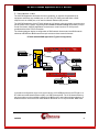
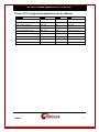
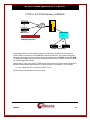
X25PAD APPLICATION USER'S MANUAL BUILD 25.X 102 SW Orange Blossom Lake City, Florida 32025-1613 phone: 386-754-5700 email: [email protected] http://www.trdcusa.com D T - 6 0 6 1 X25PAD Application U s e r ' s M a n u a l CONTENTS 1. INTRODUCTION............................................................................................................................... 4 1.2 APPLICATION SPECIFICATIONS ............................................................................................................. 5 1.3 APPLICATION BASIC ARCHITECTURE & OPERATION ............................................................................ 5 1.4 X25PAD APPLICATION CONFIGURATION............................................................................................. 6 2. APPLICATIONS COMMANDS ....................................................................................................... 8 2.1 INPUT CONVENTIONS............................................................................................................................ 8 2.2 LOGIN ................................................................................................................................................... 8 2.3 LOGOUT................................................................................................................................................ 8 2.4 CHANGE PASSWORD ............................................................................................................................. 9 2.5 HELP..................................................................................................................................................... 9 2.6 VERSION ............................................................................................................................................... 9 2.7 PLACING COMPONENTS IN SERVICE ..................................................................................................... 9 2.8 TAKING COMPONENTS OUT OF SERVICE .............................................................................................. 9 2.9 CONFIGURING GENERAL & LINK PARAMETERS ................................................................................. 10 2.10 VIRTUAL CIRCUIT CONFIGURATION .................................................................................................. 12 2.11 CONFIGURING PAD PARAMETERS .................................................................................................... 13 2.12 DISPLAY MEASUREMENTS ................................................................................................................ 15 2.13 VERIFY CONFIGURATION .................................................................................................................. 15 2.14 DISPLAYING CURRENT CONNECTIONS .............................................................................................. 15 2.15 SNOOPING X.25 TRAFFIC ................................................................................................................. 15 2.16 RESTART X.25 OPERATION .............................................................................................................. 16 2.17 PROMPT LABELS ............................................................................................................................... 16 2.18 APPLICATION COMMENTS ................................................................................................................ 16 2.19 DISPLAY OF REMOTE EIA LEADS ..................................................................................................... 16 2.20 CLOSED USER GROUPS ..................................................................................................................... 17 2.21 CONSOLE SECURITY .................................................................................................................. 17 2.22 X25PAD INSTALL (INSTALLING SOFTWARE & RESETTING THE PASSWORD)................................ 17 3. APPLICATION SOFTWARE INSTALLATION & UPGRADE ................................................ 17 4. APPENDIX A – X25PAD MEASUREMENTS AVAILABLE ..................................................... 18 5. SUPPORT FOR X.3 PAD PARAMETER VALUES..................................................................... 19 6.................................................................................................................................................................... 21 7. APPNOTE: USING X25PAD AS AN FTAM GATEWAY ........................................................... 22 8. HARDWARE WARRANTY ........................................................................................................... 25 04/22/08 2 D T - 6 0 6 1 X25PAD Application U s e r ' s M a n u a l 9. END-USER LICENSE AGREEMENT FOR SOFTWARE ......................................................... 26 SOFTWARE LICENSE ................................................................................................................................. 26 INTELLECTUAL PROPERTY RIGHTS ........................................................................................................... 26 SOFTWARE SUPPORT ................................................................................................................................ 26 EXPORT RESTRICTIONS............................................................................................................................. 26 LIMITED WARRANTY ................................................................................................................................ 26 NO OTHER WARRANTIES.......................................................................................................................... 27 LIMITATION OF LIABILITY ........................................................................................................................ 27 SPECIAL PROVISIONS ................................................................................................................................ 27 10. SALES & DISTRIBUTION ............................................................................................................. 28 11. AUTHOR........................................................................................................................................... 28 04/22/08 3 D T - 6 0 6 1 X25PAD Application U s e r ' s M a n u a l 1. INTRODUCTION The X25PAD Application eliminates the need, complexity, or expense of specialized X.25 equipment and allows any available port on a DT-4xxx, DT-2020 connected SAM, or BNS endpoint such as a SAM port, to be used for Network Element (NE) access. The X25PAD Application of the DT-6061 allows an X.25 device to be connected to a synchronous port anywhere in the network. Supporting both X.3 PAD and Pass-Through functionality on a per virtual circuit basis, X25PAD Application connections to virtual circuits on an X.25 port are provided with a telnet TCP/IP connection. The following diagram depicts a configuration of BNS network elements and non-BNS network elements with BNS/non-BNS hosts that require access to those network elements. DT-6061 with X25PAD Application (Typical Configuration) Node DT-6061 NE X.25 T S M T R K U M I C P M IP IP IP Network IP Fiber SAM X.25 Network Element BNS Host DT-4000 IP IP Hosts X.25 Network Elements In the above configuration, there is one circuit carrying X.25 LAPB frames from the DT-6061 to a DT-4000 connected Network Element (NE) or a SAM connected NE. The X.25 Network Element may be anywhere on the available networks (both BNS and IP) as the above diagram depicts. IP Hosts access the virtual circuits on these Network Elements via a TCP port number. BNS Hosts 04/22/08 4 D T - 6 0 6 1 X25PAD Application U s e r ' s M a n u a l access the virtual circuit via the UMI1. The same is true of terminal and PC devices on either the BNS or the IP network. 1.2 APPLICATION SPECIFICATIONS Number of X.25 devices per DT-6061 30 Number of Virtual Circuits per X.25 Device 1-100 PAD Service Yes (Per Virtual Circuit) X.25 Pass-Through Service Yes (Per Virtual Circuit) RFC 1006 ISO Service Yes (Per Virtual Circuit) Binary Service Yes (Per Virtual Circuit) Number of OA&M Channels available 30. One per X.25 device. Measurements Available LAPB, Packet Layer, PAD, Byte Counts, Error Counts. Alarms Yes SNMP (DT-6061 Agent) Yes Fault Tolerant Yes. Using two DT-6061 in a high availability configuration. 1.3 APPLICATION BASIC ARCHITECTURE & OPERATION 1.3.1 INTERFACE TYPES There are three distinct interface types on the X25PAD application. The Configuration Circuits This interface type is used for configuration and administration of the X25PAD application for a particular X.25 connection via Telnet. The Virtual X.25 Line Circuits For this interface type, one virtual X.25 line is configured to receive on a TCP Port. This TCP port will then listen for the TCP call from the DT-4000, UMI, etc. The specific TCP port used is the configured base + 0. The X.25 VCC (via X.3 PAD) Circuits. For this interface type, one TCP port is configured per VCC on the X.25 line. These TCP ports will listen for a call from an endpoint that requires access to the VCC. The specific TCP ports used begin at the configured base + 1 for X.25 VCC 1, and increment in proportion. 1.3.2 CIRCUIT USAGE EXAMPLE The X25PAD application would have its (B)X.25 line, and per circuit configuration entered. This includes the base TCP port number that establishes the range of TCP ports relating to that X.25 line. 1 The UMI allows both synchronous and asynchronous endpoints connected to a BNS network to access endpoints on an IP network. Similarly, endpoints on an IP network can access both synchronous and asynchronous endpoints on a BNS network. 04/22/08 5 D T - 6 0 6 1 X25PAD Application U s e r ' s M a n u a l Once restored to service, the X.25 line TCP port (offset 0 from the base) listens for in inbound call from a DT-4000, UMI, or DT-2020/SAM port. This establishes the connectivity with the remote X.25 network element endpoint. The VCC TCP ports (offset 1 – Number of Virtual Circuits) will listen on their respective TCP ports for inbound calls as well. Any host, or other IP endpoint, may make a telnet call to these TCP ports for per virtual circuit connectivity to the X.25 network element. 1.4 X25PAD APPLICATION CONFIGURATION The configuration of the X.25 application takes place on its OA&M port. That is TCP port number 10000 + its instance number in the DT-6061. The configuration required for the X25PAD application is: • Per application: This is the TCP port number to be used as a base for a range of TCP ports the application instance shall use. The synchronous transport to the X.25 network element occurs at offset zero to this base TCP port number. The individual X.25 virtual circuits are identified by the base TCP port number plus the X.25 virtual circuit port number. • Per X.25 line: These consist of the LAPB transmission window size and other link layer parameters. • Per X.25 VCC: These consist of the PAD profile associated with the VCC, the window size to be used for transmission in the X.25 packet layer, and other parameters associated on a per virtual circuit basis. The Per X.25 Line Configuration parameters are as follows: Parameter Values Default X.25 Logical Line Type DTE, DCE DCE 16 8 128, 256,512,1024 128 Bytes LAPB Tx Window Size 1-7 2 Frames Waiting ACK Time (T1) 1-60 3 Seconds Maximum Attempts to complete a Transmission (N2) 1-255 7 Seconds Action when N2 Count Exceeded3 Disc, reset. Reset Disc, reset. Reset Number of X.25 VCs Default Max Packet Size 2 Action when DISC received 4 Units 2 The 1980 standard provided for 128 byte packet sizes. The 1984 standard increased the maximum size to 256 bytes. Later standards have optionally increased that number. However, nearly all implementations of X.25 follow the 1984 standard, and it is considered the default for all implementations known to date. 3 The X25PAD application currently supports only (B)X.25 PVCs. As such a DISC action is not defined. 4 Receipt of a DISC on an (B)X.25 PVC is not valid. This is not currently supported. 04/22/08 6 D T - 6 0 6 1 X25PAD Application U s e r ' s M a n u a l The per VCC configuration parameters are as follows: Parameter Values Default Units Packet Layer Window 1-7 2 Packets Circuit Type PVC or SVC PVC PAD Inactivity Timer (T) 2-20, OFF OFF Profile ID Value, Transparent Transparent SVC calling address to use DNIC+NTN None ** SVC VCs Only ** SVC called address to use DNIC+NTN None ** SVC VCs Only ** User Data Lengh & Contents Binary Data 0xC1 ** SVC VCs Only ** Extended Calling Address NSAP None ** ISO SVC VCs ** Extended Called Address NSAP None ** ISO SVC VCs ** 04/22/08 Seconds 7 D T - 6 0 6 1 X25PAD Application U s e r ' s M a n u a l 2. APPLICATIONS COMMANDS The DT-6061 software is composed of two components. One component, called the Platform, exists to support all applications. The second component is comprised of the individual application(s). The Platform provides Operating System functions, selected interfaces, protocol stacks, SNMP functions, and system OA&M while each application uses the services of the resident Platform. 2.1 INPUT CONVENTIONS All parameters may be given on the command line. Parameters of the form name=<value> may be given in any order. For several complex commands, listed below, missing parameters, or corrections of errors in given parameters, of the form name=<value> are collected by prompting the console user. The user responds to a prompt for the name by typing the required <value> followed by newline. Defaults are supplied in some cases, so the user need only enter newline. Commands may be entered in upper or lower case. Parameters of the form name=value may use upper or lower case for name. Default values, if any, are shown in parenthesis as part of the prompt. Case is preserved for values. When a password is being requested by a prompt, input is not echoed. Backspace erases one character and @ deletes the current line of input. Most commands are killed by del key. 2.2 LOGIN Syntax: login PASSWD=<password> (The default password is “initial”) The login command is used to allow access to the other configuration commands. The PASSWD parameter is not echo suppressed. However, if the PASSWD parameter is not provided, the console prompts for a password; the response is an asterisk echo in this case. If the password is valid, the user is placed in the logged in mode. Once the console user is logged in, the balance of the commands are accessible. Note: Each application instance is allowed to be assigned a different password. 2.3 LOGOUT Syntax: logout The logout command is only allowed if the console user is logged in. It requires no arguments. It will set the console to the logged out mode. Passwords are up to seven characters in length. The characters are alphanumeric and special characters are not allowed. 04/22/08 8 D T - 6 0 6 1 X25PAD Application U s e r ' s M a n u a l 2.4 CHANGE PASSWORD Syntax: chgpass PASSWD=<old> NEWPASS=<new> CONFIRM=<new> The chgpass command is used to change a user password on the system console. The command is only allowed if the user is logged in. All three parameters must be given on the same line as the command. None of those entries are echo-suppressed. If the current password is valid, and the two entries for the new password match, the password is changed to the new value. 2.5 HELP Syntax: help [ Command ] The help command is always visible. The help command displays the currently allowed commands for the mode that the unit is currently entered. If the optional [ Command ] is provided, the displayed help will be limited to that command. 2.6 VERSION Syntax: ver The version command is only visible when the application is logged in. The command has no arguments. It displays the current build, software version, and database version of the X25PAD application. 2.7 PLACING COMPONENTS IN SERVICE Syntax: rs <link | <vc XXX>> The restore command is only visible when the application is logged in. The command is used to place the X.25 Link, or any of the X.25 virtual circuits, into service. A TCP connection is not available until the component is placed into service. At least one argument is required. That argument is the component type to be placed into service. There is only a single X.25 link, and multiple X.25 virtual circuits on that link which may be individually brought into service. Once the component is brought into service, it will await a TCP session if the connection type is rcv. If the connection type is orig, a TCP session will be established with the endpoint specified in the component configuration. Please see the sections that follow for configuration of both the link, and the virtual circuits. It should be noted that when there are multiple VC with the same TCP port (i.e. a hunt group), the restore command on any one VC in the group will act on all the VCs in the group. 2.8 TAKING COMPONENTS OUT OF SERVICE Syntax: rm <link | <vc XXX>> 04/22/08 9 D T - 6 0 6 1 X25PAD Application U s e r ' s M a n u a l The remove command is only visible when the application is logged in. The command is used to place the X.25 Link, or any of the X.25 virtual circuits, out of service. Any TCP connection using those components is automatically taken down when the component is removed from service. At least one argument is required. That argument is the component type to be removed from service. There is only a single X.25 link, and multiple X.25 virtual circuits on that link which may be individually removed from service. It should be noted that when there are multiple VC with the same TCP port (i.e. a hunt group), the remove command on any one VC in the group will act on all the VCs in the group. 2.9 CONFIGURING GENERAL & LINK PARAMETERS Syntax: link [base=<TCP Port#>] [type=<RCV|ORIG>] [dest=<IP Address>] [dport=<TCP Port>] [dxe=<DCE|DTE>] [numvcc=<#VCC>] [win=<#>] [T1=<#>] [N2=<#>] [cug=[+|-]<CUG Number>] The link command is only visible when the application is logged in. The command is used to configure a Virtual X.25 line termination. The base parameter is the TCP port number base at which the X.25 line, and the associated X.25 virtual circuits, are to be IP terminated. The default is computed as follows: Default TCP Base=((<Application Instance# > -1)*200)+30000 For example, instance #1 of the application will have its base address at 30000. The X.25 link would be connected at that TCP port number. The first VC would be at TCP 30001, and so on. When the X.25 link is to be on an incoming TCP session, the type would be set to rcv. The X.25 link would reside at the TCP port specified by the base parameter. When the X.25 link is to be on an outgoing TCP session, the type would be set to orig. The IP address would be specified by the dest parameter, and the TCP port at that IP address would be specified by the dport parameter. The dxe parameter specifies the logical gender of the (B)X.25 connection. The dxe defaults to the value of dce. When the dxe is dce, it is expected that the (B)X.25 device is a logical dte. When the dxe is dte, it is expected that the (B)X.25 device is a logical dce. Please note that it is still possible for the device to be a physical dce, or dte regardless of this value. This parameter refers only to the LAPB logical gender. The numvcc parameter is the number of X.25 virtual circuits to be supported. The default is 16. The win parameter specifies the LAPB window size to be used for transmission. The Window size is always 8 frames for receive. The default transmission window size is 2 per the ITU specification X.25. The t1 parameter specifies the value of the T1 timer. The timer defaults to the recommendation of the ITU specification X.25. It is provided as an option for non-standard configurations. The n2 parameter specifies the value of the N2 retry counter. The value defaults to the recommendation of the ITU specification X.25. It is provided as an option for non-standard configurations. 04/22/08 10 D T - 6 0 6 1 X25PAD Application U s e r ' s M a n u a l The cug parameter allows the link connection to be protected by a closed user group. These are defined with the cug command specified later in this section. Any or all cug entries may be associated with the link. 04/22/08 11 D T - 6 0 6 1 X25PAD Application U s e r ' s M a n u a l 2.10 VIRTUAL CIRCUIT CONFIGURATION Syntax: vc <vc#> [win=<#>] [ckt=< SVC | PVC >] [maxpkt=<128 | 256 | 512 | 1024>] [svc=< pad | pass | MACSTAR | RBP | ISO | BIN | SESS >] [type=<RCV|ORIG>] [dest=<IP Address>] [dport=<TCP Port>] [hport=<TCP Port>] [calling=< DNIC+NTN | DELETE >] [called=< DNIC+NTN | DELETE >] [ext_calling=<NSAP> | DELETE ] [ext_called=<NSAP> | DELETE ] [svctclass=< NONE | Throughput >] [ulen=< User Data Length >] [udata#=< Hexadecimal Value >] The VC command is only visible when the application is logged in. The command is used to configure a virtual circuit connection to a Virtual X.25 line. The <VC#> parameter refers to the virtual circuit configured on the X.25 line. It has the range of 1 through the number of circuits configured. When the X.25 virtual circuit is to be placed on an incoming TCP session, the type would be set to rcv. The X.25 virtual circuit would reside at the TCP port specified by the hport parameter. A default TCP port is unique to each VC. By using the same TCP port in multiple VCs, hunt groups may be created. The VC numbers do not need to be contiguous to create a hunt group. When the X.25 virtual circuit is to be placed on an outgoing TCP session, the type would be set to orig. The IP address would be specified by the dest parameter, and the TCP port at that IP address would be specified by the dport parameter. The win parameter refers to the packet layer window size to be used for transmission purposes. It defaults to the value of 2 per the ITU Recommendation X.25. The svc parameter allows the type of service to be performed on the virtual circuit. When the value of PAD is selected, the virtual circuit is terminated in a X.3 PAD service. When the value of PASS is selected, an X.25 pass-through service is selected. When the value of MACSTAR is selected, a proprietary interface with the MACSTAR operations system is selected. The value of ISO selects RFC 1006 encapsulation of ISO (B)X.25 over TCP/IP. The value of BIN is a straight binary interface without additional encapsulation. The value of RBP is the Reservation Boundary Protocol over TCP/IP. The value of SESS selects an implementation of the BX.25 Session Layer on this VC. This BX.25 Session Layer within the X25PAD is a vertical service above the packet layer. The BX.25 Session Layer may be used in conjunction with the BX.25 Session Layer API library, or as a standalone service. The ckt parameter allows the type of virtual circuit to be configured. The default is PVC to define a permanent virtual circuit. When defined as a PVC, the circuit will still accept call requests and clears but will not generate them. When defined as an SVC, the circuit will generate a call request when a connection is made to the VC, and a call clear when a connection to the VC is dropped. Optional parameters allow the specification of the contents of the call X.25 packet. 04/22/08 12 D T - 6 0 6 1 X25PAD Application U s e r ' s M a n u a l The calling parameter allows the specification of a calling DNIC+NTN that is contained in the call packet generated on an SVC. The default is that no calling information is provided. The DELETE option specifies the removal of the calling DNIC+NTN. The called parameter allows the specification of a called DNIC+NTN that is contained in the call packet generated on an SVC. The default is that no called information is provided. The DELETE option specifies the removal of the called DNIC+NTN. The ext_calling and ext_called parameters allows the specification of address extensions used in an ISO concatenated (B)X.25 network. The extensions allow addresses to be propagated across the subnetwork attachment where the networks are concatenated. These extensions were proposed in the 1984 X.25 specification and adopted in the 1988 X.25 specification. A value of DELETE will remove the parameter from the virtual circuit. The svctclass=< NONE | Throughput > option specifies a throughput class declared on X.25 call connect, and call accept packets. The throughput class is the same in both transmit and receive directions. As a general rule, it should always be set to NONE such that no limiting throughput class is established. All specification allowable values for throughput class are supported. These range from 75bps to 48000bps inclusive. The option is provided for interface to devices that require a throughput class to be explicitly negotiated. The ulen parameter defines the size of the User Data field in the call packet. The allowed values are one through 16 bytes inclusive. Modification of the user data field with the udata# parameter will affect the value of the user data length automatically. The udata# parameter defines the contents of one byte. The # is to be replaced with a number in the range of one through 16 inclusive (e.g. udata1=0xC1). The default user data is one byte in length and contains the value 0xC1. The maxpkt parameter specifies the size of the X.25 packet generated when the data stream has not met its termination condition and is therefore generated with the M-BIT. The actual size of the packet is 3 bytes larger to accommodate X.25 protocol overhead. 2.11 CONFIGURING PAD PARAMETERS Syntax: pad <vc #>[echo=<ON|OFF>] [fwd=< none | cr | crdrop | semi | all | GRPx>] [idle=<#ticks>] [break=<none|intr|reset|brkind>] [parity=<TRANS | EVEN | ODD>] [crlf=<none|rmt|vc|both>] [inact=<# seconds>|OFF] [cmap=< ON | OFF >] [cug=[+|-]<CUG Number>] The PAD command is only visible when the application is logged in. The command is used to configure the X.3 PAD parameters of a virtual circuit. These parameters have relevance only if the service selected on the virtual circuit is PAD. The <VC #> parameter refers to the virtual circuit configured on the X.25 line. It has the range of one through the number of circuits configured. 04/22/08 13 D T - 6 0 6 1 X25PAD Application U s e r ' s M a n u a l The echo option refers to reference #2 in the X.3 parameter list. When set to OFF, the X25PAD will not echo characters back to the IP endpoint. When set to the value of ON, all characters are to be echoed back to the IP source. The fwd=<NONE | CR | CRDROP | SEMI | ALL | GRPx> option specifies reference #3 of the X.3 parameter list. This is the forwarding condition (outside the PAD timer) which will forward data towards the X.25 virtual circuit. A value of NONE indicates that there are no character forwarding conditions. A value of CR indicates that a carriage return will forward any accumulated data (including the carriage return). A value of CRDROP indicates that a carriage return will forward any accumulated data (but not including the carriage return). A value of SEMI indicates that a semicolon will forward any accumulated data including the semicolon. A value of ALL indicates that all data is to be forwarded immediately. The ALL option has the effect of generating single user character X.25 packets on this virtual circuit. The GRPx values specify selected groups of forwarding characters. GRP1 forwards on ESC, BEL, ENQ, and NAK. GRP2 forwards on DEL, CAN, DC2. GRP3 forwards on ETX, EOT. GRP4 forwards on HT, LF, VT, and FF. Multiple forwarding conditions are allowed simultaneously. Setting fwd to a value aggregates with the previous value of fwd. The fwd=none is required to clear the forwarding conditions. The idle parameter refers to reference #4 in the X.3 parameter list. This is the time forwarding condition. When it expires, it will forward any data collected to the X.25 circuit. The timer is reset to the specified value whenever a forwarding condition is reached. The value is based on ticks of 1/20th of a second each per the X.3 specification. The break parameter refers to reference #7 in the X.3 parameter list. This is the action to be taken when a break indication (a standard telnet encapsulated value) is received from the remote IP endpoint. The value of NONE will ignore the break, and it is deleted from the data stream. The value of INTR will generate an X.25 interrupt packet. The value of RESET will generate an X.25 virtual circuit reset. The value of BRKIND will generate an X.29 “indication of break” message on the X.25 virtual circuit. The parity parameter is not present in the X.3 parameter list. It allows special parity treatment for interface to network elements that require parity. The default value is transparent operation. The value of TRANS sets the operation to be transparent. When the parity treatment is transparent, the data is not modified in either direction. The value of EVEN sets the operation to be even parity towards the (B)X.25 device, and stripped parity towards the TELNET. The value of ODD sets the operation to be odd parity towards the (B)X.25 device, and stripped parity towards the TELNET. The crlf parameter refers to reference #13 in the X.3 parameter list. This is the action to be taken when a CR is received in the data stream from the remote IP endpoint. A value of NONE indicates that there is to be no LF (line feed) insertion. A value of RMT will insert an LF following a CR whenever it is sent towards the remote IP endpoint. A value of VC will insert an LF following a CR whenever it is sent towards the X.25 virtual circuit. A value of BOTH will insert an LF following a CR in either direction. The inact option refers to the PAD inactivity timer. If enabled, the TCP session on that X.25 virtual circuit is disconnected when the inactivity timer expires. The value defaults to OFF. The cmap option provides the automatic case mapping from lower case to upper case. When ON, all lower case characters are automatically converted to upper case. When OFF, no transformations are performed. The cug parameter allows the virtual circuit connection to be protected by a closed user group. The closed user group feature is significant only for PAD service. The closed user group address entries are defined with the cug command specified later in this section. Any or all cug entries may be associated with the virtual circuit. 04/22/08 14 D T - 6 0 6 1 X25PAD Application U s e r ' s M a n u a l 2.12 DISPLAY MEASUREMENTS Syntax: dmeas <link |vc <#> > The dmeas command is only visible when the application is logged in. The command is used to display the current measurements on either the X.25 link or per virtual circuit. The LINK parameter will display the measurement information for the X.25 link being supported by this instance of the application. The VC <#> option will display the measurement information for a particular X.25 virtual circuit on the link. The virtual circuit number is in the range of one through the maximum number supported by the application. 2.13 VERIFY CONFIGURATION Syntax: vfy [ all | app | link | cug | vc <#>] The vfy command is only visible when the application is logged in. The command is used to display the configured options on the X.25 link, or a virtual circuit resident on the X.25 link. The LINK parameter will display the configuration information for the X.25 link being supported by this instance of the application. The VC <#> parameter will display the configuration information for a particular X.25 virtual circuit on the link. The virtual circuit number is in the range of 1 through the maximum number supported by the application. The APP parameter will display information about the application instance. This includes user comments, and the instance identifier. The CUG parameter will display information about the configuration of the closed user groups. 2.14 DISPLAYING CURRENT CONNECTIONS Syntax: dc The dc command is used to display all of the current connections into the X25PAD application. This includes the X.25 link, and any X.25 virtual circuit connections. The command will issue a report that shows the connection peer for each active connection. 2.15 SNOOPING X.25 TRAFFIC Syntax: snoop [OFF | L2 | ALL | <VC# Range>] [ verbose ] The X25PAD application has a diagnostic ability to snoop on either X.25 link at the LAPB layer, or on an individual circuit at the packet layer. This is done with the snoop command. All output is directed to the OA&M connection. If the command is invoked with no arguments, it produces a report of all active snooper configurations. If the command is invoked with the OFF option, all of the snooper configurations are disabled. 04/22/08 15 D T - 6 0 6 1 X25PAD Application U s e r ' s M a n u a l If the command is invoked with the L2 option, the LAPB interface to the X.25 device is snooped. Output is displayed on the OA&M session. Please note that this could be extensive for a moderately busy X.25 line. If the command is invoked with the ALL option, the LAPB interface and all of the virtual circuits that have been configured have snooping enabled. If the command is invoked with a virtual circuit number in the range of 1 through the maximum number of X.25 circuits; the packet layer of the circuit specified is snooped. The number may be specified as a range (e.g. 1-5). The additional parameter of [verbose] will display all of the data bytes in addition to the standard decoding. The output of this option may become quite voluminous. 2.16 RESTART X.25 OPERATION Syntax: restart The restart command is only visible when the application is logged in. The command is used to manually initiate a protocol restart of the X.25 link and packet layers. 2.17 PROMPT LABELS Syntax: label [ “Any Label” | NONE ] The prompt on the application console may be customized with a label up to sixty characters in length. Spaces and special characters are allowed within the double quotes. The double quotes are required on this command. The value of none deletes any existing label on the prompt. The current configuration is displayed during a verify configuration, by invoking the label command without arguments, or merely by the prompt display. 2.18 APPLICATION COMMENTS Syntax: comment [ L1=”Any Comment”] [ L2=”Any Comment”] [ L3=”Any Comment”] The X25PAD application may have comments which are displayed with the verify configuration command. Up to three lines of comments are available. Each line may have a comment up to 64 characters in length. Each comment is double quoted to allow for spaces to be embedded. A comment with no characters (i.e. “”) is used to delete a comment which is not desired. It is not necessary to delete prior to adding a new comment. The new comment shall replace the existing comment at the line specified. 2.19 DISPLAY OF REMOTE EIA LEADS Syntax: deia The deia command allows a user to display the EIA leads of the BX.25 Network Element connection from a DT-4000 or SAM device. The command does not affect data transport, and may be done at any time. 04/22/08 16 D T - 6 0 6 1 X25PAD Application U s e r ' s M a n u a l 2.20 CLOSED USER GROUPS Syntax: cug <CUG Number> [ipaddr=<IP Address>] [submask=<IP Mask>] The CUG command allows the definition of address sets to create multiple closed user groups. The address sets are then used by the link, console, and virtual circuits in creating individual closed user groups. The <CUG Number> has a range of one through sixteen. 2.21 CONSOLE SECURITY Syntax: console [cug=[+|-]<CUG Number>] The CONSOLE command allows the assignment of a closed user group to the administration session. The closed user group must include the current administrator to prevent accidental lockout. This restriction is enforced. 2.22 X25PAD INSTALL (INSTALLING SOFTWARE & RESETTING THE PASSWORD) Syntax: install [ key=<software key> ] The X25PAD application has a unique software key. The installation of the key is performed by the factory, and need only be done if the software is changed in the field. When executed without arguments, the install command will display the significant information needed to manufacture the software key. The <software key> is an eight-character alphanumeric which is unique to the X25PAD application on this DT-6xxx. When the install command is entered with the key=<software key> option, the instance user password is reset to the original value of initial. The X25PAD application need be installed only once on a DT-6xxx. The key becomes available for all X25PAD instances immediately. 3. APPLICATION SOFTWARE INSTALLATION & UPGRADE An application may be initially installed, or upgraded, using the install command available on the platform console. Please note that this command is not the X25PAD install command that is used for key installation on the instance console. Refer to the DT-6061 Platform User's Manual and refer to the section titled: Application Software Installation & Upgrade 04/22/08 17 D T - 6 0 6 1 X25PAD Application U s e r ' s M a n u a l 4. APPENDIX A – X25PAD MEASUREMENTS AVAILABLE This appendix itemizes the measurements available using the display measurements (dmeas) command. There are two options to the dmeas command. These are link and vc. The link option provides X.25 Link level measurements, and the vc option provides per virtual circuit measurements. The base measurements are always displayed, and the error and exception counters are only displayed if nonzero. The link level measurements available are as follows: Measurement Description Type Number of LAPB Frames Received Base Number of LAPB Frames Transmitted Base Number of LAPB Bytes Received Base Number of LAPB Bytes Transmitted Base Number of Invalid Frames Received. Base Number of Frames Received with Channel Out of Range Base The per virtual circuit measurements available are as follows: Measurement Description Type Number of Packets Received from X.25 Link Base Number of Packets Sent to X.25 Link Base Number of Bytes Received from X.25 Link Base Number of Bytes Sent to X.25 Link Base Number of Call Request Packets Received Exception Number of Call Accept Packets Received Exception Number of Clear Request Packets Received Exception Number of Clear Confirmation Packets Received Exception Number of Interrupt Packets Received Exception Number of Interrupt Confirm Packets Received Exception Number of REJ Packets Received Exception Number of RNR Packets Received Exception Number of Reset Request Packets Received Exception Number of Reset Confirmation Packets Received Exception 04/22/08 18 D T - 6 0 6 1 X25PAD Application U s e r ' s M a n u a l 5. SUPPORT FOR X.3 PAD PARAMETER VALUES The X25PAD supports the relevant X.3 PAD parameters. Since the X25PAD is not a physical device, some of the parameters are not readily applicable. Responses via X.29 will carry default values if queried. The table below will indicate all the X.3 parameters, and the support of these parameters by the X25PAD application. Ref # Description Supported Options Note 1 PAD recall 0 – None 2 Echo 0 – No Echo 1 – Echo Yes 3 Data Forwarding Characters 0 – None 2 – CR 126 – All Characters Yes 4 Idle Delay 0-255 Ticks are in 1/20th of a second. Yes 5 Ancillary Device Control 0 – None Configured on DT-4000 or SAM/DT-2020 port configuration No 6 Control of PAD service signals and PAD command signals. 0 – No PAD service signals are transmitted. DT-4000 or SAM is DTE service center. No 7 Operation of PAD on receipt of break from IP 0 – Nothing 1 – Send X.25 Interrupt 2 – Send X.25 Reset 4 – X.29 “Indication of Break” Yes 8 Discard Output 0 – Normal Data Delivery No 9 Padding after CR 0 – No Padding after CR No 10 Line Folding 0 – No line folding No 11 Binary Speed 18 – 64000bps For Reporting Only No 12 Flow Control of the PAD 0 – No use of X-ON and X-OFF These are functions of the DT-4000 and SAM devices. No 04/22/08 User Command session provided by Datakit CC or DT-4000 or DT-2020. Config No 19 D T - 6 0 6 1 X25PAD Application U s e r ' s M a n u a l 13 LineFeed Insertion after CR 0 – No Linefeed Insertion 1 – Insert Linefeed after CR towards IP. 2 – Insert Linefeed after CR from IP Yes 14 Padding after Linefeed 0 – No Padding after LF No 15 Editing 0 – No use of editing. User command session performed via the DK CC, the DT-4000, and the DT2020. No 16 Character Delete None User command session performed via the DK CC, the DT-4000, and the DT2020. No 17 Line Delete None User command session performed via the DK CC, the DT-4000, and the DT2020. No 18 Line Display None User command session performed via the DK CC, the DT-4000, and the DT2020. No 19 Editing PAD service signals 0 - None No 20 Echo Mask 0 - None No 21 Parity 0 – No generation or checking. 22 Page Wait 0 - Disabled 23 Input field size 0 - Undefined User command session performed via the DK CC, the DT-4000, and the DT2020. No 24 End of Frame Signals 0 – Undefined Size EOF is determined and encoded per the RFC since this is an IP application. No 25 Extended Data Forwarding Signals 0 – No extended Data No 26 Display Interrupt 0 – No display interrupt No 27 Display Interrupt Confirmation 0 – No display interrupt confirmation. No 28 Diacritic Character Coding 0 – Basic Coding No 04/22/08 Parity performed by DT4000 or SAM. No No 20 D T - 6 0 6 1 X25PAD Application U s e r ' s M a n u a l 29 Extended Echo Mask 0 – No Extended Echo Mask No 6. 04/22/08 21 D T - 6 0 6 1 X25PAD Application U s e r ' s M a n u a l 7. APPNOTE: USING X25PAD AS AN FTAM GATEWAY The FTAM protocol is used by ISO compliant network equipment for the transfer of files between two systems or endpoints. Typically, these endpoints are on disjoint segments of an X.25 network. That is, they are closed networks that are concatenated by an intermediate network. All the network segments are X.25 based and the call setup information needed to establish a connection was contained in extended address features that were added to the Call Setup packet during the 1984 revision to the BX.25 specification. The X.25 address extensions are aimed primarily at the carrying of the NSAP addresses across concatenated networks. These addresses are independent of the subnetwork addressing scheme, and will be used at the boundary between subnetworks to derive the Subnetwork Point of Attachment (SNPA) for the next stage of a call. For an X.25 network, the SNPAs are the calling and called DTE address carried at the start of the call request packet immediately after the packet type identifier. The CCITT originally assumed that the address extension field needed to be 32 decimal digits. However, ISO subsequently defined this value to be 40 digits in the 1988 version of the X.25 specification. The X25PAD application supports the 40 digits defined in the 1988 specification for extended calling parameters. As TCP/IP networks became prevalent, RFC 1006 was proposed as a means to deliver FTAM packets in lieu of the X.25 network specified by ISO. Because TCP is a byte stream and not a packet protocol, a header was added to each FTAM message. To date, three versions of the RFC1006 FTAM protocol have been presented. The X25PAD application supports the most current version (#3). In this use, the X25PAD application acts as a gateway between an intermediate X.25 network and the TCP/IP host interface. The X25PAD presents the extended addressing needed to support concatenated X.25 networks, and mediates between the RFC1006 TCP/IP interface and the ISO X.25 interface. This is selectable on a per virtual circuit basis. An example of such a deployment is as follows: 04/22/08 22 D T - 6 0 6 1 X25PAD Application U s e r ' s M a n u a l TCP/IP to ISO FTAM Gateway IP IP Hosts FTAM Clients DT-4xxx DT-6xxx X25PAD Application X.25 EWSD FTAM Server In the diagram above, the FTAM clients on the TCP/IP hosts communicate with the X25PAD application in the native RFC1006 FTAM protocol. The X25PAD mediates with the ISO based X.25 implementation of the FTAM protocol. The physical X.25 links are connected to a DT-4xxx serial port remote from either the DT-6xxx or the FTAM client hosts. In addition, integration with a BNS network is easily achieved with a UMI module. Consider the following diagram: 04/22/08 23 D T - 6 0 6 1 X25PAD Application U s e r ' s M a n u a l TCP/IP to ISO FTAM Gateway via BNS/DK DK/BNS SAM IP U M I U T M IP Hosts FTAM Clients SAM DT-6xxx X25PAD Application X.25 EWSD FTAM Server In the diagram above, the only change made was a UMI as the mediation point between the TCP/IP network infrastructure and the BNS/DK network infrastructure. Any variant of SAM may be used for the serial connection. Options include the SAM 64/504, a DT-4000, and the DT-SAM. The SAM and DK/BNS node need not be collocated with each other or with the DT-6xxx on which the X25PAD application resides. Configuration of a VC to be used for FTAM service requires only the selection of the ISO protocol and the extended address parameters for the SVC call setup. An example for VC #1 follows: vc 1 ext_calling=5551212 ext_called=1234567 svc=iso All of the other SVC parameters remain the same. 04/22/08 24 D T - 6 0 6 1 X25PAD Application U s e r ' s M a n u a l 8. HARDWARE WARRANTY The warranty period for hardware shall be ninety (90) days from the date of delivery, and the warranty for software shall be 90 days from the date of delivery. Replacements and repairs are guaranteed for the longer of the remaining original warranty period or 90 days. 04/22/08 25 D T - 6 0 6 1 X25PAD Application U s e r ' s M a n u a l 9. END-USER LICENSE AGREEMENT FOR SOFTWARE This License Agreement ("License") is a legal contract between you and the manufacturer ("Manufacturer") of the system ("HARDWARE") with which you acquired software product(s) identified above ("SOFTWARE"). The SOFTWARE may include printed materials that accompany the SOFTWARE. Any software provided along with the SOFTWARE that is associated with a separate end-user license agreement is licensed to you under the terms of that license agreement. By installing, copying, downloading, accessing or otherwise using the SOFTWARE, you agree to be bound by the terms of this LICENSE. If you do not agree to the terms of this LICENSE, Manufacturer is unwilling to license the SOFTWARE to you. In such event, you may not use or copy the SOFTWARE, and you should promptly contact Manufacturer for instructions on return of the unused product(s) for a refund. SOFTWARE LICENSE You may only install and use one copy of the SOFTWARE on the HARDWARE (unless otherwise licensed by Manufacturer). The SOFTWARE may not be installed, accessed, displayed, run, shared or used concurrently on or from different computers, including a workstation, terminal or other digital electronic device (“Devices”). Notwithstanding the foregoing and except as otherwise provided below, any number of Devices may access or otherwise utilize the services of the SOFTWARE. You may not reverse engineer, decompile, or disassemble the SOFTWARE, except and only to the extent that such activity is expressly permitted by applicable law notwithstanding this limitation. The SOFTWARE is licensed as a single product. Its component parts may not be separated for use on more than one HARDWARE. The SOFTWARE is licensed with the HARDWARE as a single integrated product. The SOFTWARE may only be used with the HARDWARE as set forth in this LICENSE. You may not rent, lease or lend the SOFTWARE in any manner. You may permanently transfer all of your rights under this LICENSE only as part of a permanent sale or transfer of the HARDWARE, provided you retain no copies, you transfer all of the SOFTWARE (including all component parts, the media and printed materials, any upgrades, this LICENSE and, if applicable, the Certificate(s) of Authenticity), and the recipient agrees to the terms of this LICENSE. If the SOFTWARE is an upgrade, any transfer must also include all prior versions of the SOFTWARE. Without prejudice to any other rights, Manufacturer may terminate this LICENSE if you fail to comply with the terms and conditions of this LICENSE. In such event, you must destroy all copies of the SOFTWARE and all of its component parts. INTELLECTUAL PROPERTY RIGHTS The SOFTWARE is licensed, not sold to you. The SOFTWARE is protected by copyright laws and international copyright treaties, as well as other intellectual property laws and treaties. You may not copy the printed materials accompanying the SOFTWARE. All title and intellectual property rights in and to the content which may be accessed through use of the SOFTWARE is the property of the respective content owner and may be protected by applicable copyright or other intellectual property laws and treaties. This LICENSE grants you no rights to use such content. All rights not expressly granted under this LICENSE are reserved Manufacturer and its licensors (if any). SOFTWARE SUPPORT SOFTWARE support is not provided by Manufacturer, or its affiliates or subsidiaries separate from the HARDWARE. For SOFTWARE support, please contact your supplier of the HARDWARE. Should you have any questions concerning this LICENSE, or if you desire to contact Manufacturer for any other reason, please refer to the address provided in the documentation for the HARDWARE. EXPORT RESTRICTIONS You agree that you will not export or re-export the SOFTWARE to any country, person, or entity subject to U.S. export restrictions. You specifically agree not to export or re-export the SOFTWARE: (i) to any country to which the U.S. has embargoed or restricted the export of goods or services, which as of March 1998 include, but are not necessarily limited to Cuba, Iran, Iraq, Libya, North Korea, Sudan and Syria, or to any national of any such country, wherever located, who intends to transmit or transport the products back to such country; (ii) to any person or entity who you know or have reason to know will utilize the SOFTWARE or portion thereof in the design, development or production of nuclear, chemical or biological weapons; or (iii) to any person or entity who has been prohibited from participating in U.S. export transactions by any federal agency of the U.S. government. LIMITED WARRANTY Manufacturer warrants that (a) the SOFTWARE will perform substantially in accordance with the accompanying written materials for a period of ninety (90) days from the date of shipment from TeleComp R&D or a designated manufacturer. Software support is limited to the hours of 9AM to 5PM ET Monday through Friday excluding TeleComp R&D observed holidays. An extended warranty may be purchased at additional cost. Any implied warranties on the SOFTWARE are 04/22/08 26 D T - 6 0 6 1 X25PAD Application U s e r ' s M a n u a l limited to ninety (90) days. Some states/jurisdictions do not allow limitations on duration of an implied warranty, so the above limitation may not apply to you. Manufacturer's and its suppliers' entire liability and your exclusive remedy shall be, at Manufacturer's option, either (a) return of the price paid, or (b) repair or replacement of the SOFTWARE that does not meet this Limited Warranty and which is returned to Manufacturer with a copy of your receipt. This Limited Warranty is void if failure of the SOFTWARE has resulted from accident, abuse, or misapplication. Any replacement SOFTWARE will be warranted for the remainder of the original warranty period or thirty (30) days, whichever is longer. NO OTHER WARRANTIES TO THE MAXIMUM EXTENT PERMITTED BY APPLICABLE LAW, MANUFACTURER AND ITS SUPPLIERS DISCLAIM ALL OTHER WARRANTIES, EITHER EXPRESS OR IMPLIED, INCLUDING, BUT NOT LIMITED TO IMPLIED WARRANTIES OF MERCHANTABILITY, FITNESS FOR A PARTICULAR PURPOSE AND NONINFRINGEMENT, WITH REGARD TO THE SOFTWARE AND THE ACCOMPANYING WRITTEN MATERIALS. THIS LIMITED WARRANTY GIVES YOU SPECIFIC LEGAL RIGHTS. YOU MAY HAVE OTHERS, WHICH VARY FROM STATE/JURISDICTION TO STATE/JURISDICTION. LIMITATION OF LIABILITY To the maximum extent permitted by applicable law, in no event shall Manufacturer or its suppliers be liable for any damages whatsoever (including without limitation, special, incidental, consequential, or indirect damages for personal injury, loss of business profits, business interruption, loss of business information, or any other pecuniary loss) arising out of the use of or inability to use this product, even if Manufacturer has been advised of the possibility of such damages. In any case, Manufacturer's and its suppliers' entire liability under any provision of this License shall be limited to the amount actually paid by you for the SOFTWARE and/or the HARDWARE. Because some states/jurisdictions do not allow the exclusion or limitation of liability for consequential or incidental damages, the above limitation may not apply to you. SPECIAL PROVISIONS The SOFTWARE and documentation are provided with RESTRICTED RIGHTS. Use, duplication, or disclosure by the United States Government is subject to restrictions as set forth in subparagraph (c)(1)(ii) of the Rights in Technical Data and HARDWARE Software clause at DFARS 252.227-7013 or subparagraphs (c)(1) and (2) of the Commercial HARDWARE Software-Restricted Rights at 48 CFR 52.227-19, as applicable. Manufacturer is TeleComp R&D or it’s designee manufacturer., 102 SW Orange Blossom, Lake City, Florida, 32025. If you acquired the SOFTWARE in the United States of America, this Software License are governed by the laws of the State of Florida, excluding its choice of laws provisions. If you acquired the SOFTWARE outside the United States of America, local law may apply. This LICENSE constitutes the entire understanding and agreement between you and the Manufacturer in relation to the SOFTWARE and supercedes any and all prior or other communications, statements, documents, agreements or other information between the parties with respect to the subject matter hereof. 04/22/08 27 D T - 6 0 6 1 X25PAD Application U s e r ' s M a n u a l 10. SALES & DISTRIBUTION CBM of America, Inc. Mr. Mike Stephens 1455 West Newport Center Drive Deerfield Beach, Florida 33442 800-881-8202 954-698-9104 Fax: 954-360-0682 www.cbmusa.com Datatek Applications, Inc. Mr. Dan Conklin 379 Campus Drive, Suite 100 Somerset, New Jersey 08873 732-667-1080 Fax: 732-667-1091 www.datatekcorp.com 11. AUTHOR Comments and Questions regarding this document or the products covered within this document should be addressed to the author Angel Gomez via email at [email protected] or via telephone at 386-754-5700. ©Copyright 2002, 2008 TeleComp Research & Development Corp. ©Copyright 1998, 2002 TeleComp Inc. All Rights Reserved Printed in USA Datakit and StarKeeper II NMS are registered trademarks of Lucent Technologies. 04/22/08 28