1
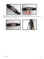
The lowering cord maybe sacrificed after lowering is completed, as it will not interfere with the
operation of the instrument.
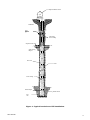
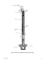
Backfilling will keep pace with the rate of removal of casing and the sequential release of the spider
magnets.
Overfilling could lead to settling within the drilling casing, which could be difficult to remove and
under filling could leave the walls of the borehole unsupported and liable to collapse, both,
scenarios better avoided.
Care should be taken with granular backfills, to avoid bridging of the backfill and the creation of
voids within the backfill column due to over-rapid filling.
Water poured down the borehole after the placement of every 0.5m’s worth of fill, will discourage
bridging and benefit the installation.
2.03 Instrument Preparation
Careful and complete preparation of the instrument’s components before borehole installation
commences is particularly important.
The quantities of 3m long access tubes are calculated to suit the depth of the borehole, and
amassed, together with the number of spider magnets specified for the installation, a datum
magnet and two end caps.
Installation equipment will include the chosen release method equipment of release pin or
pneumatic cutters and sufficient connecting cord or pneumatic tubing to reach the deepest spider
magnet installation from the top of the borehole.
PVC glue is used to fix the bottom end cap, the datum magnet and to cement joints of the 3m
lengths of access tube together, to form a single rigid length.
No bonding is required for EC inclinometer casing.
For pushdown magnets, a placing head and sufficient lengths of placing tubes to reach the deepest
spider magnet installation are required.
Making sure that all gluing surfaces are clean, dry and preferably de-greased using a solvent
cleaner, the datum magnet is glued to the bottom length of tubing, 0.5 to 1.0m above the bottom
or female end of the access tube. The bottom end cap is then glued onto the female end of the
tube.
Setting time for the glue will depend on temperature conditions and so the equipment should be
handled accordingly, ensuring that the glued fittings are not disturbed and remain dry until they
have set sufficiently.
The position of the ground level relative to the last length of access tubing once installed to the
correct depth, should be calculated and marked with a band of coloured tape.
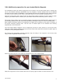
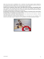
If pneumatic cutters are being used to release the spider magnets, they should be lubricated (by
dismantling if necessary) and checked for smooth and free operation before final fitting to their
spider magnet, particularly if they have been previously used and their mechanism possibly
contaminated with hardened grout.
The cutting piston should move freely when air pressure is applied to the pneumatic tubing and
excess pressure should exhaust from the air release holes when the piston has fully displaced.
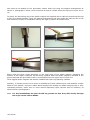
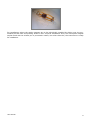
After verifying that sufficient length of pneumatic release tubing is fitted to reach the installed
magnet depth, plus at least 2m, all available pneumatic cutters may then be fitted to the spider
magnets, by wrapping nylon fishing line of 11 kg (25lb) breaking strain, around the spurs in each
leaf spring leg and fastening all together, with the nylon line of the upper loop passing through the
User Manual
6