1
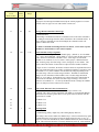
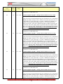
First Menu
Level
Mode Number
37
Second
Menu
Level
35
Value
Range
Mode Description and Instructions
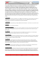
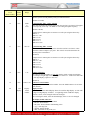
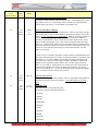
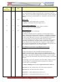
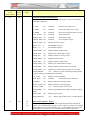
Long Duration Timer Display Format – Display Zone 2
Default=2 – This mode determines the display zone two format for long duration
timer operation (When Mode 32-18=1).
37
36
37
37
0,1
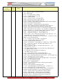
Time Adjustment Range
This mode determines the scale used by Mode 4 to adjust the real time clock.
0=Seconds per month. 1=Seconds per year (default). A setting of 1, or seconds per
year, is recommended when the high precision oscillator is installed (HX option). See
also Mode 4.
37
38
0,1
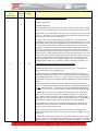
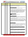
Timer Precision Control
0=disabled (default), 1=enabled - This mode improves timer precision when
displaying fractions of a second, but changes the real time seconds each time timer is
started or stopped. USE ONLY WITH SHORT DURATION TIMERS. If real time
accuracy is a priority, then disable this mode. If timer precision is a priority,
especially when displaying tenths and hundredths of a second, then enable this more.
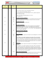
37
39
2-10, 12-20,
22-30
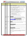
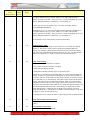
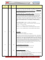
Timer Signal Light Blinking Precursor
Available for down timers only – (default=0) setting this parameter will blink the
green and/or yellow signal lights near the completion of their respective cycle.
Setting Mode 37-39 to 1 through 10 will blink the yellow light near the completion of
the warning time. The point at which the light begins blinking is determined by
dividing the warning time by the value of Mode 37-39. For example, if Mode 3739=3, then the warning time will be divided by three. This is the point at which the
yellow light will begin blinking. The blink rate is fixed at two cycles per second.
Setting Mode 37-39 to 11-20 will blink the green light before the signal turns yellow.
A value of ten will be subtracted from the mode value to produce the divisor. Setting
Mode 37-39 to 21-30 will blink the green and yellow lights near the completion of
their respective cycle. Twenty is subtracted from the mode value to produce the
divisor.
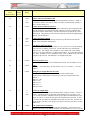
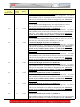
37
40
0,1,2
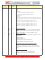
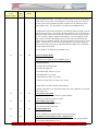
Timer Days or Hours Master/Slave Mode
This mode allows elapsed days or hours to be sent and received over sync lines.
0=disabled (default), 1=elapsed days, 2=elapsed hours. The counter field is used to
send the days or hours; therefore, this mode cannot be used with checksum serial
communications. See display modes 21 and 22. See also Mode 32-18, 37-34, 37-35
and 37-36.
37
41
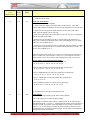
0-99 tenths
of a second
First Alternating Display Duration
First in Sequence to Display – This delay value allows easier viewing when
alternating display modes are used. For example, when alternating between time and
date, the time could display for 5 seconds while the date only displays for 2 seconds.
This reduces confusion when numbered displays are alternating back and forth.
Mode 37-13 acts as a multiplier for Modes 37-41, 37-42 and 37-43. For example, if
37-13=10, then setting Mode 37-41=99 would cause a 99 second delay.
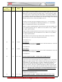
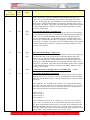
37
42
0-99 tenths
of a second
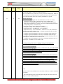
Second Alternating Display Duration
Second in Sequence to Display – This delay value allows easier viewing when
alternating display modes are used. For example, when alternating between time and
date, the time could display for 5 seconds while the date only displays for 2 seconds.
This reduces confusion when numbered displays are alternating back and forth.
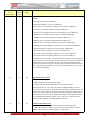
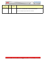
Long Duration Timer Display Format – Display Zone 3
Default=2 – This mode determines the display zone three format for long duration
timer operation (When Mode 32-18=1).
77