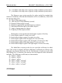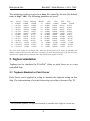
1
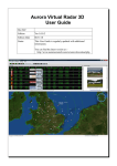
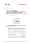
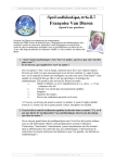
DYNASIM© ---------------------------------- AN INTERACTIVE, PHYSICS-BASED, REAL-TIME SHIP SIMULATOR ---------------------------------- User Manual ---------------------------------- J.-K. Choi, X. Wu, and G. L. Chahine ---------------------------------- Version 3.2.5 May 2012 ------------- DYNAFLOW, INC. 10621-J IRON BRIDGE ROAD JESSUP, MD 20794 U.S.A. Phone: (301) 604-3688 Fax: (301) 604-3689 E-mail: [email protected] http://www.dynaflow-inc.com DYNAFLOW, INC. DYNASIM© - USER MANUAL v. 3.2.5 - 7.093 Table of Contents Intellectual Property and Software License Agreement ............ 3 1. Introduction ................................................................................ 4 2. Technical Basis ........................................................................... 4 3. Installation .................................................................................. 5 4. Running DYNASIM© .................................................................... 6 4.1 SETUP OF THE ENVIRONMENT ........................................................................................... 7 4.2. PLACEMENT OF SHIPS ..................................................................................................... 12 4.3 OPERATION OF THE USER CONTROLLED SHIP FROM THE CONTROL PANEL ....................... 16 4.4 OPERATION OF THE USER CONTROLLED SHIP USING A JOY STICK .................................... 17 4.5 OPERATION A SHIP IN A PRESCRIBED ITINERARY ............................................................. 18 4.4 MODIFICATION OF PROPERTIES OF A LAUNCHED SHIP ..................................................... 19 4.5 VIEW OPTIONS ................................................................................................................ 20 4.6 DISPLAYING THE SIMULATED TIME DURATION ................................................................ 20 4.7 SIMULATION SPEED ADJUSTMENT .................................................................................. 21 4.8 PREPARING SHIP CHARACTERISTICS DATA FILES ............................................................ 22 4.9 PREPARING SHIP DATA FILE............................................................................................. 24 4.10 OUTPUT ........................................................................................................................ 31 5. Tugboat simulation ..................................................................32 5.1. TUGBOATS MODELED AS POINT FORCES ....................................................................... 32 5.2 TUGBOAT MODELED AS A CONTROLLED SHIP ................................................................ 36 6. Notes ..........................................................................................37 1 DYNAFLOW, INC. DYNASIM© - USER MANUAL v. 3.2.5 - 7.093 Abstract This manual provides a description of DYNASIM©. The code is designed to simulate multi-ship dynamics in restricted water, in the presence of waves, wind, currents, and obstacles. General topography, channel configuration, and environmental conditions can be input by the user. The simulator can be used to generate multiple ship tracks to evaluate harbor safety from a system perspective and estimate the likelihood of collision for various types of vessels, traffic densities, navigation channels geometries and environmental conditions. It can also be used for continual training of masters and pilots to minimize human error, and by harbor designers and port managers for structures and waterway design, modification, improvement and implementation of safety measures. This manual also explains how to prepare input files, how to run the code, and what results can be output. Sample input and output files are provided. These example input and output files and the software are provided on the program disks DYNASIM© are Copyrights © of DYNAFLOW, INC. 1995-2012. All rights reserved. DYNAFLOW, INC. may have patents and/or pending patent applications covering subject matter in this document. The furnishing of this document does not convey any license to these patents. Other brands or product names are trademarks (™) or registered trademarks (©) of their respective holders. No part of this document may be reproduced or transmitted in any form or by any means, electronic or mechanical, for any purpose, without the express written permission of DYNAFLOW, INC. 2 DYNAFLOW, INC. DYNASIM© - USER MANUAL v. 3.2.5 - 7.093 Intellectual Property and Software License Agreement This agreement governs your use of the DYNASIM© product and any material enclosed with it, including any manuals, disks, hardware, PC cards, and computer programs. Grant of License. This agreement permits you to use one copy of the product, which is licensed as a single product. The software is “in use” on a computer when it is loaded into the temporary memory (i.e. RAM) or installed into the permanent memory (e.g., hard disk or other storage device) of that computer. Copyright and Restrictions. The software is owned by DYNAFLOW, INC. and is protected by United States copyright laws. The Software is protected by U.S. Copyright Laws, Patents, and Trade Secrets. You must treat the Software like any other copyrighted material, except that you may make one copy of the Software solely for backup archival purposes. You may not reverse engineer, decompile or disassemble the Software, except to the extent applicable law expressly prohibits the foregoing restriction. DYNAFLOW, INC. may have patents and/or pending patent applications covering subject matters in this document. The furnishing of this document does not give you any license to these patents. DYNAFLOW, INC. grants you a non-exclusive license to use one copy of the DYNASIM© Software program. Limited Warranty. For 30 thirty days from your date of purchase, DYNAFLOW, INC. warrants that the media on which the Software is distributed are free from defects in materials and workmanship. DYNAFLOW, INC. will repair or replace the Software provided that (a) the defective Software is returned to DYNAFLOW, INC. or an authorized dealer within 60 days from the date of purchase and (b) you have completed and returned the enclosed registration. Limitation of Liabilities. In no event will DYNAFLOW, INC. be liable for any indirect, special, incidental, economic or consequential damages arising out of the use or inability to use the DYNASIM© Product. In no event will DYNAFLOW, INC.’s liability exceed the amount paid by you for the Product. Restricted Rights. No part of this document may be reproduced or transmitted in any form or by any means, electronic or mechanical, for any purpose, without the express written permission of DYNAFLOW, INC. Other brands or product names are trademarks or registered trademarks of their respective holders. 3 DYNAFLOW, INC. DYNASIM© - USER MANUAL v. 3.2.5 - 7.093 1. Introduction The PC Windows Ship Maneuvering Simulator, DYNASIM©, is a user friendly ship dynamics simulator that will incorporate Systems Identification Techniques in future versions to determine ship maneuvering characteristics. Once the parameters are known the simulator reproduces ship motion under the action of waves, wind, nearby piers, obstacles or other ships, it is presently able to operate in three modes: user manually controlled, standard ship classification maneuvers (i.e. tests recommended by the International Maritime Organization for evaluating the maneuverability of a ship), and computer controlled maneuvers including prescribed routes and obstacle avoidance. Multithreading enables simultaneous simulation of several ships. DYNASIM© incorporates on-screen buttons for maneuvering controls and input of environmental conditions, which helps personnel training, ship design, and navigation planning. The initial efforts to develop the device were funded by Small Business Innovation Research (SBIR) awards from the National Science Foundation, the Department of Defense, and the National Oceanic & Atmospheric Administration. 2. Technical Basis The simulator is based on the state-of-art knowledge of ship dynamics. A comprehensive model for ship dynamics under cruising and maneuvering conditions is implemented. It incorporates a large variety of options to simulate vehicles (large ships and small boats), with different engine types, weather and sea conditions, and land and coastal configurations. Some of the navigation code rules have been implemented for allowing auto piloting of multiple ships in the computer controlled mode. The hydrodynamic characteristics implemented in DYNASIM© can be updated using the results from the advanced computational hydrodynamics code developed at DYNAFLOW, INC., 3DYNAFS©, which can handle nonlinear, large amplitude vehicle motion, high waves, surf zone waves, etc. An additional 4 DYNAFLOW, INC. DYNASIM© - USER MANUAL v. 3.2.5 - 7.093 major characteristic of future versions of DYNASIM© is its incorporation of a multi-objective system identification technique to determine the vehicle parameters. This would enable the autopilot to adjust the vehicle parameters based on feedback from the ship response to the pilot commands. The simulator employs modular mathematical models for the various components of the ship (hull, propeller(s), rudder(s), and thrusters) and environmental effects (wind, current, waves) and waterway (bottom, pier walls) to achieve a sophisticated mathematical model for the ship. The models are based on collective experience resulting from development of many simulators. 3. Installation DYNASIM© operates on a PC under Windows NT 4 and up. The software is operated and controlled through a user-friendly Graphical User Interface (GUI). The various options and tasks are accessed through a series of pull down menus and easy-access buttons. The following simple steps will guide the user through the installation process. 1. To install this software, user needs to be logged in as an “administrator” or have administrator rights. 2. Open the folder of the distribution CD and double click “Install.cmd” to start the installation. 3. The installation first creates C:\DynaSIM directory and copies all the necessary files for the user to run DYNASIM©. Then it continues to install three ocx files (AX_UG.ocx, ACWAnim.ocx, HeadingControl.ocx) to the system automatically. If the installation runs successfully, a message box with “DLLRegisterServer in AX_UG.ocx succeeded” will appear, click OK and continue until all three ocx files are installed successfully. If all three ocx files are installed successfully, go to step 5. 5 DYNAFLOW, INC. DYNASIM© - USER MANUAL v. 3.2.5 - 7.093 4. If the batch file doesn’t run successfully, the three ocx files have to be installed manually. To do so, copy the three ocx files to the SYSTEM32 folder (either C:\WINNT\SYSTEM32 for Windows NT or C:\WINDOWS\SYSTEM32 for Windows XP). If REGSVR32.EXE is not present in the SYSTEM32 folder, also copy it from the CD to the system32 folder. Then, open a console window for a command prompt (Start → Run → type “cmd” → OK) and change directory to the SYSTEM32 folder, and execute the following command: REGSVR32.EXE AX_UG.ocx After getting the message “DLLRegisterServer in ACWAnim.ocx succeeded”, continue to register the second and third ocx files, i.e., REGSVR32.EXE ACWAnim.ocx and REGSVR32.EXE HeadingControl.ocx. 5. The installation is now completed, and DYNASIM© can run in C:\DynaSIM. 6. In order to run DYNASIM© in a different folder, the executable DYNASIM©.exe, all ship model files *.shp (i.e., Mariner.shp, etc.) and itinerary files *.env (i.e. Sample Itinerary 1.env, etc.) need to be copied to the working directory of the user’s choice where the user wants to make runs and place all the input and output files. Important: It is imperative that the C:\DynaSIM directory and all .ocx and .dll files remain on the computer for the program to run properly. 4. Running DYNASIM© Double clicking on the DYNASIM© icon to start the DYNASIM© software. This invokes the Graphical User Interface allowing for interactive and arbitrary manipulation of the on-screen control/steering devices in real time, and a graphical display of multiple ships and sea environments. A snap shot of the typical working window of DYNASIM© is shown in Fig.1. A scale of one grid size is shown on the upper left corner; it changes with the grid as the window is zoomed in and out. 6 DYNAFLOW, INC. DYNASIM© - USER MANUAL v. 3.2.5 - 7.093 4.1 Setup of the environment By clicking the shortcut buttons on the left side of the window, the users can set up the surrounding environment, in which the simulation will be conducted. These buttons are described below. Figure 1. Initial window of DYNASIM© after starting the program. Zone Selector After the enviroment has been set up, if a change to the properties of a certain zone is desired, just highlight this button, then place the cursor inside of the zone that needs to be changed and double click the left mouse button, a property change dialog window will pop up, in which the user can change the properties of the zone, delet the zone, or shift the zone by a specified distance. 7 DYNASIM© - USER MANUAL v. 3.2.5 - 7.093 DYNAFLOW, INC. Another way to shift the whole zone to a desired new place is to drag the zone when both left and right mouse buttons are pressed. Release the mouse buttons when the zone has been dragged to the desired place. If the user only wants to change one zone point to a new place, he can put the cursor on that point, drag the mouse to the desired place while the right mouse button is pressed down. Insert Shore Click this button, then place the cursor to the desired location in the simulation area and left click the mouse to plot a shore area by connecting segments to form a closed area. A colored area representing the shore appears in the window. Insert Harbor Click this button, then point the cursor to the desired location in the simulation area and left click the mouse to plot a harbor area. A colored area representing the harbor appears in the window. Insert Lighthouse Click this button, then point the cursor to the desired location in the simulation area and left click the mouse to insert a light house. Insert Iso-Depth Figure 2. Input of iso-depth properties. Click this button, then point the cursor to the desired location in the simulation area and left click the mouse to plot an area that has a given constant water depth. When the user finishes drawing the closed curve, a dialog box will appear as shown in Fig. 2. Type in the value (in feet), and 8 DYNASIM© - USER MANUAL v. 3.2.5 - 7.093 DYNAFLOW, INC. click OK. A colored area with the depth value is shown on the window. The same dialog window appears when the user wants to change the properties of the iso-depth zone using the zone selector. Insert Iso-Winds Click this button, then point the cursor to the desired location in the simulation area and left click the mouse to plot an area on which the effect of a wind with constant strength and given direction is modeled. When the user finishes drawing the closed curve, a dialog box will appear as shown in Fig. 3. Type in the direction (in degree, relative to the north clockwise), velocity magnitude (in knots), and click OK. A colored area with the values is shown in the window. The same dialog window appears when the user wants to change the properties of the isowind zone using the zone selector. Figure 3. Input of iso-winds properties. Insert Iso-Current First click this button, then point the cursor to the desired location in the simulation pane and left click the mouse to plot an area, on which the effect of a current with a constant velocity and a given direction is modeled. When the user finishes drawing the closed curve, a dialog box will appear as shown in Fig. 4. Type in the direction (in degrees, relative to the north clockwise), velocity magnitude (in knots), and click OK. The same dialog window appears when the user wants to change the properties of the iso-current zone using the zone selector. Figure 4. Input of iso-current properties. 9 DYNASIM© - USER MANUAL v. 3.2.5 - 7.093 DYNAFLOW, INC. Insert Iso-Waves Click this button, then point the cursor to the desired location in the simulation area and left click the mouse to plot a area, on which the effect of a wave with a constant height and a given direction is modeled. When the user finishes drawing the closed curve, a dialog box will appear as shown in Fig. 5. Type in the direction (in degrees, relative to the north clockwise), choose the Sea State, and click OK. A colored area with the values is then shown in the window. The same dialog window appears when the user wants to change the properties of the iso-waves zone using the zone selector. Figure 5. Input of iso-wave properties. Insert Itinerary Prescribed itinerary are required to run the simulator in computer controlled maneuvering mode. To add an itinerary, click this button, then point the cursor to the desired location in the simulation area and left click the mouse to plot an itinerary as desired. A safe navigation zone is required to each itinerary, when the user finishes drawing the itinerary, double click the right mouse button, a safe zone dialog box will appear as shown in Fig. 6. Type in the range of the safe navigation zone (the width) and the recommended speed for each segment of the itinerary, and click OK. A colored itinerary with the itinerary number is shown in the window. The same dialog window appears when the user wants to change the properties of the safe zone when using the zone selector to change the location of the itinerary. After setting up the environment, the user can save the environment setting to a file by clicking Environment on the menu, choosing Save Environment File As, specifying the desired name of the environment file, and clicking Save. To load a saved environment setting, click Environment on the menu, choose Open Environment File As, specify the desired name of the 10 DYNAFLOW, INC. DYNASIM© - USER MANUAL v. 3.2.5 - 7.093 environment file to load, and click Open. A snap shot of the screen of a sample setting is shown in Fig. 7. Figure 6. Input of an itinerary. Figure 7. Setup example of a simulation environment. 11 DYNASIM© - USER MANUAL v. 3.2.5 - 7.093 DYNAFLOW, INC. 4.2. Placement of ships Insert ship* Click this button, then point the cursor to the desired location in the simulation pane and left click the mouse to insert a ship. A dialog box appears, which allows the user to select the desired ship and operation mode (Fig. 8). You can select a ship model either: 1. from the Model list of predefined ship models, or 2. by providing a ship model data file that you create. To use a user created ship data file, select User-Specified under the Model list, and then enter the file name of the ship data file under Ship Properties. The user must select from one of three types of modes to launch a ship: User Controlled, Standard Maneuver, or Autopilot Itinerary. * Figure 8. Add ship dialog. Autopilot Itinerary is available in the Traffic and Tugboat Versions only. 12 DYNAFLOW, INC. DYNASIM© - USER MANUAL v. 3.2.5 - 7.093 If the User Controlled is selected, the user can maneuver the ship either through the graphic control panel using a mouse/keyboard or with a joy stick. If a joy stick is connected to the PC, it becomes the default control device. The ship maneuvering and/or itinerary data of the user controlled ship can be output by checking the Output Maneuver Data File and/or Output Itinerary Data File. If Standard Maneuver is selected, the ship can perform one of the classical maneuvers that identify the ship hydrodynamic characteristics. Three types of maneuvers are pre-programmed: Turning circles (Circles), Zigzag or Spiral maneuvers. For these maneuvers the user needs to provide a rudder angle associated with the selected standard maneuver. Additionally, the user can select Obtain ship characteristics to generate the ship characteristics that can be later used in autopilot simulations, and select Pre-defined to make the ship perform a maneuvering specified in a maneuvering data file, such as the one generated from a simulation under the User Controlled ship option when Output Maneuver Data File is checked. To load a pre-defined maneuvering data file, click the Search button which opens a file dialog window, and select the desired maneuvering data file. In order to select the Autopilot Itinerary, either the user specifies the itinerary from a file, or there is already defined itinerary (see the Insert Itinerary section). In the latter case, the user must check the Read Itinerary Data File, and provide the file name by clicking the Search button and select the file. Click Show Itinerary to display the itinerary read from the file. The user can output 13 DYNAFLOW, INC. DYNASIM© - USER MANUAL v. 3.2.5 - 7.093 the itinerary associated with the ship to an itinerary file by checking the Output Itinerary Data File option. For a ship in the Autopilot Itinerary, the computer will act as an autopilot to maneuver the ship along the itinerary following the navigation rules. The user can use the default auto-piloting rules by selecting Use Default Values or specify new auto-piloting rules by selecting Specify New Values. In addition, the user can control how often the software checks the ship position relative to the route by providing desired time step interval value in the edit box of the Route-checking time step interval. The added mass coefficients can be either read the from the Added Mass section of a ship model data file or calculated internally from the geometrical characteristics of the ship without using the data in the Added Mass section of the ship model data file. The user must select either Calculated Internally or Read from File under the Hydrodynamic Coefficients. The pull-down menu of Hull Coefficients is to provide the advanced user a method to change the hull coefficients. The default hull coefficients are calculated from the input ship data file. In general, users are not advised to change the coefficients. However, here are the meanings of the indices of hull coefficients: 0 : Yv , 1 : Yr 2 : Nv , 3 : Nr 4 : Yvv , 5 : Yvr , 6 : Yrr 7 : N rr , 14 DYNAFLOW, INC. DYNASIM© - USER MANUAL v. 3.2.5 - 7.093 8 : Yvvr , 9 : Yrrv 10, 11, 12 : coefficients associated with roll motion. In current version, these three coefficients are not user adjustable. 13 : cross-flow resistance coefficient (similar to YV , but used only when the drift angle is very large) In the above expressions of the hull hydrodynamic coefficients, Y is the sway force and N is the yaw moment. The subscript v is for the sway velocity, and the subscript r is for the yaw velocity. The selected coefficient is increased by a percentage of the default value. The percentage is specified in the Rate in edit box. Under Simulation Options, the user must identify if the ship being launched will involve a tug boat simulation. Select Apply tug point forces to simulate tugging forces applied on the ship, or select Is a tugboat to enable the ship being added to act as a tugboat. If none of these two boxes are checked, the ship is considered as a regular ship that does not involve any tug interactions. If Wait signal before start is checked, the ship won’t start motion until the user clicks the Start/Stop button on the control panel as shown in Fig. 9. If Incld confined water effects option is checked, the simulation includes side wall and floor effects in a confined water way. The maneuvering data of the ship in the simulation will be saved in a trace file (see section 4.10 Output) by unchecking the No Output option and specifying the desired trace file name and maximum time steps to output the data. Finally, by clicking OK, the ship will be added to the simulation environment. 15 DYNAFLOW, INC. DYNASIM© - USER MANUAL v. 3.2.5 - 7.093 4.3 Operation of the user controlled ship from the control panel DYNASIM© can handle single and twin engine propulsion systems. The number of engines of a ship is provided by the number of propellers in the ship data file. The same control panel will be used for both single and twin engine ships. Fig. 9 shows the status of the control panel for a twin-engine ship (left) and a single engine ship (right). If the ship added is a twinengine ship, the check box Indepdnt Engine Ctrl is enabled. If the checkbox is left unchecked, the two engines work in synchronized mode, i.e. two engines are always set to the same engine throttle setting when one of the two engine throttle controls is changed. If the checkbox is checked, the user can control the two engines separately. If the ship is a single engine ship, the disabled check box will show One engine model and the throttle control and engine status display on the right are disabled. The single engine is controlled by the throttle control slide on the left side and the engine status is also displayed on the left. Figure 9. Control panel status for a twinengine ship (left) and a single engine ship (right). The user can use the slide bars on the control panel to control a usercontrolled ship. 16 DYNAFLOW, INC. DYNASIM© - USER MANUAL v. 3.2.5 - 7.093 Propulsion: The throttle control for the main engine is represented by the vertical slide bar in the middle of the control panel, sliding the bar enables the user to adjust the engine RPM. Sliding up from Stop increases the forward thrust. Sliding down from Stop increases the backward thrust. The bow and stern thrusters are represented by two horizontal slide bars, sliding to the right, the direction of the thrust is toward the starboard side, sliding to the left, a thrust toward the portside is applied to the ship. The current thrust is displayed in the form of percentage of the maximum thrust that the thruster can generate. Maneuver: The slide bar for the Rudder Contol is located below the thruster controls in the lower part of the control panel, sliding the bar enables the user to adjust the rudder angle to control the ship motion direction. Slide left to turn the ship to the left. Slide right to turn the ship to the right. 4.4 Operation of the user controlled ship using a joy stick If a joystick is presented, it becomes the default control device for a user controlled ship, DYNASIM© is programmed to use a generic joystick. Fig. 10 show a typicle joystcik which includes the following elements: 1. Stick (rudder) 2. Base 3. Trigger 4. Extra buttons 5. Autofire switch 6. Throttle 7. Hat Switch (POV Hat) 8. Suction Cup Figure 10. A typical Joystick DYNASIM© uses the Stick to control the rudder, the rudder turns left or right proportionally as the stick is shifted to left or right. 17 DYNAFLOW, INC. DYNASIM© - USER MANUAL v. 3.2.5 - 7.093 The propulsion in DYNASIM© is controlled by the combination of Throttle and POV hat. The Throttle controls the throttle of the engines, the selection of the engines is determined by the POV hat. When the POV hat is in the neutral position, the main engines are controlled. When the POV hat is push to up position, the bow thruster is controlled, when it is pushed to down position, the stern thruster is controlled. If the ship is a Figure 11. Specify Navigation Rules. twin-engine ship, the left engine is controlled when the POV hat is push to left position, when it is pushed to the right position, the right engines is controlled. 4.5 Operation a ship in a prescribed itinerary* If the user specifies a ship to be launched into an Autopilot Itinerary when adding a ship to the simulation environment (at least one prescribed itinerary must exist, otherwise, an error will be reported), the user has the option to use the default values or specify new values for the navigation rules. If the user chooses to specify new values for these navigation rules by selecting Specifying New Values in the Add Ship dialog, a dialog window as shown in Fig. 11 pops up, through which the user can specify new values for navigation rules in different situations. * This capability is not available in the Basic Version. 18 DYNAFLOW, INC. DYNASIM© - USER MANUAL v. 3.2.5 - 7.093 After the navigation rules have been decided, an itinerary selection window (Fig. 12) pops up, specify the desired route number and click OK. If a valid itinerary has been selected, a new dialog window (Fig. 13) pops up, through which the user can specify where and in which direction to launch the ship. In the same dialog window, the user can also decide whether to keep the itinerary default properties or not. If the user wants to specify new properties, he can change the properties for each segment of the itinerary through a dialog window as shown in Fig. 14. Figure 12. Choose Itinerary. Figure 13. Choose Release Point. Figure 14. Specify New Itinerary Properties. 4.4 Modification of properties of a launched ship After a ship has been launched into the simulation environment, the user still has the capability to change the properties of the ship by pointing the cursor on the ship and double clicking the right mouse button. A dialog window as shown in Fig. 15 pops up. The user can pause or resume the motion of the ship, change the ship from the current type to another user 19 DYNASIM© - USER MANUAL v. 3.2.5 - 7.093 DYNAFLOW, INC. controlled type such that he can maneuver the ship through the control panel, delete the ship from the simulation environment, display the ship status through the control panel, and relocate the ship to a desire location by providing the coordinates of the new location. The user can also drag the ship to a desired position by putting the cursor over the ship, moving the mouse while pressing the left mouse button. Figure 15. Modify Ship Properties. 4.5 View options Zoom Click this button enables the user to zoom in and zoom out in the selected area. Restore (1:1) Click this button will set the view of the window to the initial setting. 4.6 Displaying the simulated time duration DYNASIM© can display the duration of a ship simulated time, i.e. from the time it is launched into the simulation environment until the current time. This is shown in the Simulation Time Display window (Fig. 16). The time is displayed in HH:MM:SS format (HH for hours, MM for minutes, and SS for 20 DYNAFLOW, INC. DYNASIM© - USER MANUAL v. 3.2.5 - 7.093 seconds elapsed). The time displayed on the window is for the same ship for which status information is displayed on the control panel (Fig. 9). The user can show or hide this window by clicking view -> Show time from the main frame as shown in Fig. 17. Figure 16. The time display window. Figure 17. Show / hide time display window. 4.7 Simulation Speed Adjustment The ship simulation proceeds in discrete time steps, the simulation time step size can be modified by clicking Options→ Time Step Specifications on the main window frame. A dialog window as shown in Fig. 18 will pop up to allow the user to change the time step size which is the physical time represented by each time step. The change of time step size will apply globally to all the ships and the time step size will be maintained through the simulation until it is changed the next time. Figure 18. Time step specification dialog window. 21 DYNAFLOW, INC. DYNASIM© - USER MANUAL v. 3.2.5 - 7.093 4.8 Preparing ship characteristics data files The turning and cruising characteristics of a ship can be used in DYNASIM© by overriding the default values used for route control for the ship. This information can be provided to DYNASIM© through three files. Followings are the detailed information of these files: 1. Ship performance data file: This file is named in the format of “performance_stt_SHIPNAME.pef”, where SHIPNAME should be the same as the ship data file name. For an example, if “Mariner” ship is selected, the ship performance data file should be named as “performance_stt_Mariner.pef” to be used by DYNASIM©. The file provides the information of engine regime and the corresponding ship speed when ship keeps a straight course at a steady state. Below is an example of “performance_stt_Mariner.pef” file. 10 5 6 … 5.94922 9.91509 Here, the first line is the total number of regimes the ship has, and it is followed by data pairs that specify “Engine regime” and “Ship speed”. 2. Ship turning radius performance data file: This file is named in the format of “performance_rdd_SHIPNAME.pef” where SHIPNAME should be the same as the ship model name. For an example, if “Mariner” ship is selected, the ship turning radius performance data file should be named as “performance_rdd_Mariner.pef” to be used by DYNASIM©. The file provides the information of ship turning characteristics for a given rudder angle. A sample “performance_rdd_Mariner.pef” file is shown below: 19 22 DYNASIM© - USER MANUAL v. 3.2.5 - 7.093 DYNAFLOW, INC. -40 -35 … 430.431 454.798 402.315 432.329 29.17 25.27 0 0 204.039 195.616 22.142 20.98875 The first line is the total number of data sets included in the file, each data set is ordered as “θ, alat, dfwd, mlat, mlat_var, mfwd, mfwd_var”. The definitions of alat, dfwd, mlat, and mfwd are shown in Fig. 19. θ is the rudder angle, and mlat_var and mfwd_var are the average variances of mlat and mfwd among different engine regimes. All units are meter except the rudder angle θ which is in degrees. 3. Ship turning rate performance data file: This file is named in the format of “performance_trt_SHIPNAME.pef” where SHIPNAME should be the same as the ship model name. For an example, if “Mariner” ship is selected, the ship turning radius performance data file should be named as “performance_trt_Mariner.pef” to be used by DYNASIM©. The file provides the information of ship turning rate at a given engine regime and rudder angle for steady ship turning. A sample “performance_trt_Mariner.pef” file should look like below: 105 5 5 5 … -40 -35 -30 -0.257167 -0.263259 -0.265563 Here, the first line is the total number of data sets included in the file, and each data line following the first line is composed of “engine regime, θ, turning rate” in order. Units of θ and turning rate are degree and degree per second, respectively. 23 DYNASIM© - USER MANUAL v. 3.2.5 - 7.093 DYNAFLOW, INC. d lat a lat A d fwd m lat B m fwd O Figure 19. Ship turning characteristics. 4.9 Preparing ship data file The specifications of ship parameters must be prepared in a ship model file, *.shp. For example Mariner.shp has the following values. The user can modifiy the values of the paramerters according to their requirements. <Hull data> 167.880005, 23.200001, 7.400000, 8.100000, [1 [2 [3 [4 length] beam] draftb] drafts] 24 DYNAFLOW, INC. DYNASIM© - USER MANUAL v. 3.2.5 - 7.093 16818.000000, [5 displacement] 1800.000000, [6 lateral_abovewater_area] 240.000000, [7 transverse_abovewater_area] -3.500000, [8 center_pressure_location] 10.000000, [9 dist_from_air_to_base] -16.500000, [10 Xg] 3.000000, [11 Ho] 17.000000, [12 trans_cross_sect_No] 10.100000, [13 Zg_true] 160.000000, [14 Visual ship length] <Propeller data> 6.700000, [1 propeller_diameter] 1.000000, [2 propeller_pitch_ratio] 4.000000, [3 numbers_blades] 0.494000, [4 propeller_area_ratios] 1.000000, [5 number_propellers] 18.000000, [6 distance_between_propeller_axes] 1.000000, [7 dist_betw_prop_axis_and_base] 1, [8 rotation: 1-R 2-L] <Rudder data> 25.200001, [1 rudder_area] 7.300000, [2 rudder_height] 1.000000, [3 number_rudders] 29.100000, [4 dist. rudders,or totalArea] 0.223000, [5 compensation_coefficient] 7.300000, [6 dist_betw_up_tip_chord_and_base] 7.300000, [7 height_balance_part] 0.0, [8 turnrate (not used)] <Approached speed table> 20.000000, [1 full speed ahead] 15.000000, [2 maneuver speed ahead] 12.500000, [3 mean speed ahead] 10.000000, [4 slow speed ahead] 6.000000, [5 dead speed ahead] 93.000000, [6 full RPM ahead] 69.699997, [7 maneuver RPM ahead] 58.10000, [8 mean RPM ahead] 46.500000, [9 slow RPM ahead] 27.900000, [10 dead RPM ahead] 25 DYNAFLOW, INC. DYNASIM© - USER MANUAL v. 3.2.5 - 7.093 <Engine data> 1, [1 engine_type: 1-diezel 2-steam] 19500.000000, [2 dizel_power] 0.870000, [3 part_power_ahead] 1.000000, [4 part_rpm_ahead] 40.000000, [5 deley_regim_regims] 0.620000, [6 part_rpm_contr] <CPP pointers data> 16.000000, [1 full speed ahead] 10.000000, [2 maneuver speed ahead] 9.000000, [3 half speed ahead] 8.000000, [4 slow speed ahead] 6.000000, [5 dead speed ahead] -13.000000, [6 full astern pointer] -8.000000, [7 half astern pointer] -4.000000, [8 slow astern pointer] -2.000000, [9 dead astern pointer] 0.000000, [10 stop pointer] 2.000000, [11 dead ahead pointer] 4.000000, [12 slow ahead pointer] 5.000000, [13 half ahead pointer] 6.000000, [14 maneuver ahead pointer] 13.000000, [15 full ahead pointer] 1.200000, [16 full_ahead_cntrl_pitch] 120.000000, [17 init_rps_cntr_pitch] <Sea data> 0.000000, [1 Mean draft to water depth ratio] 0.000000, [2 Wind velocity] 270.000000, [3 Wind direction] 0.000000, [4 Current velocity] 270.000000, [5 Current direction] 0.000000, [6 Wave height, sea state, 0 to 9] 0.000000, [7 Wave direction, was 270] <Bow thruster data> 500.000000, [1 bow_power] 3.100000, [2 hydr_area_bow_trsr] 3.100000, [3 stream_area_bow_trsr] 95.000000, [4 coord_bwt_axise] 20.000000, [5 bow_time] 26 DYNAFLOW, INC. DYNASIM© - USER MANUAL v. 3.2.5 - 7.093 <Stern thruster data> 500.000000, [1 strn_power] 3.100000, [2 hydr_area_strn_trsr] 3.100000, [3 stream_area_strn_trsr] -95.000000, [4 coord_strn_axise] 20.000000, [5 strn_time] <Initial values> 0.000000, [1 Velocity_in_x_direction] 0.000000, [2 Velocity_in_y_direction] 0.000000, [3 Angular_velocity_about_z_axis] 0.000000, [4 Angular_velocity_about_x_axis] 93.000000, [5 Rotation per minits] 0.000000, [6 Head angle, was 0] 0.000000, [7 Roll angle] 0.000000, [8 Distance_CG_in_x_direction, 1.4] 0.000000, [9 Distance_CG_in_y_direction, 1.2] <Maneuver type> 1.000000, [1 type: 0-free 1-Circulation 2-Zigzag 3-Spiral_test ] 1.000000, [2 discretization step (sec, float number format)] 30.000000, [3 print time: ship body display time (sec)] 2.000000, [4 Max_mnvr_time_min] 50.000000, [5 Max_rudder_deflection, 0] 30.000000, [6 Angle_of_zig_zag_maneuver_switch] 10.000000, [7 motion equations results display time (sec)] <Regimes> 9, [1 One engine: initial regime: 0-full astern 4-stop 9-full ahead] 9, [2 One engine: ordered regime, 4] 4, [3 Left engine: initial regime] 4, [4 Left engine: ordered regime] 4, [5 Right engine: initial regime] 4, [6 Right engine: ordered regime] <Added Mass> 0.02 [1 admassx_coeff, admassx/mMass] 0.7 [2 admassy_coeff, admassy/mMass] 0.7 [3 admassz_coeff, admassz/mMass] 0.002 [4 adinex_coeff, adinex/mMass/mLength**2] 0.7 [5 adiney_coeff, adiney/mMass/mLength**2] 5 [6 adinez_coeff, adinez/mMass/mLength**2] <Print Data> 27 DYNAFLOW, INC. 1, 1, 1, 1, DYNASIM© - USER MANUAL v. 3.2.5 - 7.093 [1 Hull force: 1-yes, 0-no] [2 Rudder force] [3 Propeller force] [4 Kinematic] Note 1: The number of rudders specified under <Rudder data> is neglected and is set to be equal to the number of propellers specified under <Propeller data>. Note 2: When there are two propellers, the rotation direction specified under <Propeller data> is interpreted as the rotation direction of the starboard side propeller. The rotation of the port side propeller is assumed to be opposite to the rotation of the starboard side propeller. Each line of the above input data is described in detail below: The entries in the Hull data section should be ordered as follows. 1. 2. 3. 4. 5. 6. 7. 8. 9. 10. 11. 12. 13. 14. Ship hull length (meter) Beam of the hull (meter) Daft at bow (meter) Draft at stern (meter) Displacement of the ship (cubic meter) Lateral area of the ship structure above the waterline (square meter) Transverse area of the ship structure above the waterline (square meter) Distance from midship to the longitudinal center pressure above waterline (meter, positive toward bow) Distance from waterline to base (meter) Longitudinal center of gravity w.r.t. midship (meter, positive toward bow) Metacentric height (meter) Not used in the current version Vertical center of gravity w.r.t. waterline (meter, positive upward) The length of the ship for visual display (meter) 15. 16. 17. 18. In Propeller data section, the following information is provided. Diameter of the propeller (meter) Pitch ratio of the propeller (pitch/diameter) Number of blades of the propeller Expanded area ratio of the propeller 28 DYNAFLOW, INC. DYNASIM© - USER MANUAL v. 3.2.5 - 7.093 19. Number of propellers of the ship 20. Distance between the axes of two propellers (meter, meaningful only for twin propeller ships) 21. Vertical distance from the ship base to the propeller axis (meter) 22. Direction of propeller rotation (1 = right handed propeller, 2 = left handed propeller) In Rudder data section, the following information is provided. Moving part of the rudder area (square meter) Rudder height (meter) Number of rudders Total area of the rudder including moving and non-moving part (square meter) 27. Rudder compensation coefficient (use 0.223) 28. Distance from the base to tip of the rudder (meter) 29. Height of the balanced part of the rudder (meter) 30. Turn rate of the rudder (degree/second, not used in the current version) 23. 24. 25. 26. In the Approached speed table, the approach speed of the ship at different engine regime and the corresponding propeller rotational speed. 31. Ship speed at Full regime (knot) 32. Ship speed at Maneuver regime (knot) 33. Ship speed at Half regime (knot) 34. Ship speed at Slow regime (knot) 35. Ship speed at Dead regime (knot) 36. Rotational speed of propeller at Full regime (RPM) 37. Rotational speed of propeller at Maneuver regime (RPM) 38. Rotational speed of propeller at Half regime (RPM) 39. Rotational speed of propeller at Slow regime (RPM) 40. Rotational speed of propeller at Dead regime (RPM) 41. 42. 43. 44. 45. The Engine section has the following information. Engine type Engine output (horsepower) The ratio of astern power to the ahead power The ratio of astern RPM to ahead RPM Delay to reach steady status for engine regime change (second, not implemented yet) 29 DYNAFLOW, INC. DYNASIM© - USER MANUAL v. 3.2.5 - 7.093 46. Ratio of for counter rotation RPM (for air pressure contra-moment starting) to nominal engine RPM The CPP pointer section has the information for controllable pitch propellers. This section is for future implementation. In the current version, this section is neglected. The Sea section has the following information. 47. Ratio of mean draft of the ship to water depth 48. Wind velocity (knot) 49. Wind direction (degree, 0 = wind blowing from the east, 90 = wind blowing from the north) 50. Current velocity (knot) 51. Current direction (degree, 0 = current to the east, 90 = current to the north) 52. Sea state (0 - 9) 53. Wave direction (degree, 0 = waves to the east, 90 = waves to the north) Note the above information will be overridden by the environment set up if the ship is placed inside any environmental zones. The Bow thruster and the stern thruster sections provide information about the bow and stern thruster. 54. Output power of bow or stern thruster (horsepower) 55. Hydrodynamic area of the bow or stern thruster (square meter) 56. Area of the flow stream of the bow or stern thruster (square meter, usually the same as hydrodynamic area) 57. Longitudinal coordinate of the bow or stern thruster location (meter, bow positive) 58. Time for bow or stern thruster to reach steady rotation speed (second) The Initial values section provides the initial values of the ship velocities and location. 59. Initial ship velocity in the x direction of the ship coordinate system (knot) 60. Initial ship velocity in the y direction of the ship coordinate system (knot) 61. Initial yaw velocity (degree/s) 62. Initial roll velocity (degree/s) 63. Initial propeller rotational speed (RPM) 64. Initial ship heading (degree) 65. Initial roll angle (degree) 30 DYNAFLOW, INC. DYNASIM© - USER MANUAL v. 3.2.5 - 7.093 66. x coordinate of the ship center of gravity in ship coordinate system (meter) 67. y coordinate of the ship center of gravity in ship coordinate system (meter) The Maneuver type section provides the values needed for standard ship maneuver simulations. Note that this information will be overridden by values from the add-ship dialog GUI. 68. Type of ship maneuvering 69. Time step size of ship simulation (second) 70. Duration of data output (second) 71. Duration to perform the specified maneuver (minutes) 72. Maximum deflection angle of the rudder (degree) 73. Angle of zigzag maneuver (degree) 74. Frequency of data output (second) 75. 76. 77. 78. 79. 80. The Regimes section provides the initial engine regimes of the ship. Initial engine regime of a single screw ship Initial ordered engine regime of a single screw ship Initial engine regime of the left engine of a twin screw ship Initial ordered engine regime of the left engine of a twin screw ship Initial engine regime of the right engine of a twin screw ship Initial ordered engine regime of the right engine of a twin screw ship The Added Mass section provides the user specified coefficients for added mass. This section is optional, and these added mass coefficients are effective only when the user chooses Read from File for Hydrodynamic Coefficients in the Add Ship Dialog (Fig. 8). Otherwise, the software uses semi-empirical values determined internally. The added mass coefficients are dimensionless. 81. admassx / mMass 82. admassy / mMass 83. admassz / mMass 84. adinex / mMass / mLength2 85. adiney / mMass / mLength2 86. adinez / mMass / mLength2 4.10 Output 31 DYNASIM© - USER MANUAL v. 3.2.5 - 7.093 DYNAFLOW, INC. The simulation results are saved in a trace file, named by the user (the default name is ship**.dat). The following quantities are saved. time 0 1 2 3 4 5 6 7 8 9 10 11 12 Xcoord +0.0000 +10.2794 +20.5581 +30.8361 +41.1136 +51.3904 +61.6665 +71.9421 +82.2171 +92.4914 +102.7651 +113.0382 +123.3108 Ycoord +0.0000 +0.0011 +0.0024 +0.0033 +0.0031 +0.0011 -0.0033 -0.0106 -0.0214 -0.0363 -0.0556 -0.0799 -0.1096 Heading +0.0000 -0.0066 -0.0188 -0.0360 -0.0575 -0.0829 -0.1117 -0.1437 -0.1786 -0.2163 -0.2565 -0.2991 -0.3440 Rudder +0 +0 +0 +0 +0 +0 +0 +0 +0 +0 +0 +0 +0 xYaw +0.0000 -0.0002 -0.0003 -0.0002 -0.0000 +0.0002 +0.0004 +0.0005 +0.0004 +0.0002 +0.0000 -0.0002 -0.0003 zYaw +0.0000 -0.0001 -0.0002 -0.0003 -0.0004 -0.0004 -0.0005 -0.0006 -0.0006 -0.0007 -0.0007 -0.0007 -0.0008 Roll +0.0000 -0.0114 -0.0271 -0.0387 -0.0398 -0.0281 -0.0060 +0.0202 +0.0429 +0.0559 +0.0566 +0.0469 +0.0321 Drift +0.0000 -0.0126 -0.0264 -0.0411 -0.0562 -0.0717 -0.0872 -0.1028 -0.1183 -0.1337 -0.1488 -0.1636 -0.1781 The units of the output are second for time, meter for Xcoord and Ycoord, degree for Heading and Rudder, radian/second for xYaw and zYaw, and degree for Roll and Drift angles. Note that the xYaw and zYaw are angular velocity around x and z axis (roll and yaw angular velocity). 5. Tugboat simulation Tugboats can be simulated in DYNASIM© either as point forces or as a user controlled ship. 5.1. Tugboats Modeled as Point Forces* Point forces can be applied to a ship to simulate the tugboats acting on that ship. The representation of a point force acting on a ship is shown in Fig. 20. * This expanded capability for tugboat interactions is available in the Tugboat Version only. 32 DYNASIM© - USER MANUAL v. 3.2.5 - 7.093 DYNAFLOW, INC. X (xTi , yTi ) fYi Ti fXi Fti L Y Cp B Figure 20. Tugboat as a point force acting on a ship. B and L are the beam and length of the ship, Ti is the contact point of coordinates (xTi, yTi) between tugboat i and the ship (note that the origin of the X-Y coordinate system is located at the ship center of gravity CP), Fti is the force acting on the ship by the tugboat i with fxi and fyi its components along the X and Y axes. The point forces are input by a user through the Tug Point Force Table dialog window as shown in Fig. 21 in which each point force is specified by its location (x/L and y/B are the x and y normalized by L and B respectively) and magnitude (F_x and F_y are the components fxi and fyi). The user can specify how many point forces are applied to the ship by editing the Number of force points edit box. Up to 20 point forces can be applied to a ship simultaneously through the dialog window. 33 DYNAFLOW, INC. DYNASIM© - USER MANUAL v. 3.2.5 - 7.093 Figure 21. The dialog window of Tug Point Force Table. The user can choose to apply the tug point forces to the ship instantly after its input to the table by checking the checkbox Apply force instantly. It the checkbox is left uncheck, the user can apply or stop applying the tug point forces to the ship by toggling the Apply/Stop tug forces Button. The message shown in the Status at the bottom of the dialog window indicates the current status of the tug forces. 34 DYNAFLOW, INC. DYNASIM© - USER MANUAL v. 3.2.5 - 7.093 Figure 22. The Add Ship dialog. The Tug Point Force Table dialog window will be automatically activated when it is linked with a ship and the point forces will apply to that ship. The user can link the point forces with a ship when it is newly added to the simulation or is selected after it has been added to the simulation. To link with a new ship, the user can check Apply tug point forces in the Add Ship dialog as shown in Fig. 22. To select or change to a ship that has been added to the simulation, the user can select the Selector on the tool bar, point the Selector 35 DYNAFLOW, INC. DYNASIM© - USER MANUAL v. 3.2.5 - 7.093 on the ship of interest, right click the mouse to activate the Modify Ship Dialog as shown in Fig. 23, and then click the Apply tug point forces button. Figure 23. The Modify Ship Dialog. 5.2 Tugboat Modeled as a Controlled Ship* The ship-tugboat interaction model implemented in DYNASIM© will be activated when any one of the two interacting ships is a tugboat. A tugboat can be added to the simulation through the Add Ship dialog as shown in Fig. 22. The ship is treated as a tugboat if the checkbox Is a tugboat is checked. The ship model list has also been expanded to include a tugboat ship model (When the tugboat on the list is selected, the Is a tugboat checkbox is checked automatically). Once the tugboat is launched into the simulation as a User Controlled Ship, the user can control the tugboat using the control panel to perform the tugging process. * This expanded capability for tugboat interactions is available in the Tugboat Version only. 36 DYNAFLOW, INC. DYNASIM© - USER MANUAL v. 3.2.5 - 7.093 6. Notes DYNASIM© is under constant development, any feedback from users is highly appreciated. Customers will be notified of the newest versions when they are available. 37