1
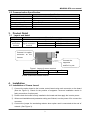
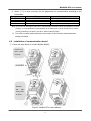
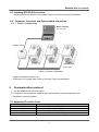
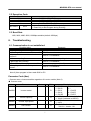
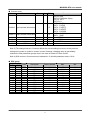
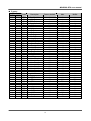
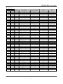
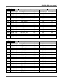
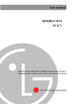
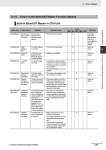
User manual
MODBUS-RTU
SV-iC5
- Read this manual carefully before installing, wiring, operating, servicing
or inspecting the drive. Keep this manual within easy reach for quick reference.
1
MODBUS-RTU user manual
Thank you for purchase of LS Modbus-RTU Option Board!
SAFETY PRECAUTIONS
l Always follow safety precautions to prevent accidents and potential hazards from occurring.
l Safety precautions are classified into “WARNING” and “CAUTION” in this manual.
WARNING
CAUTION
Indicates a potentially hazardous situation which, if not
avoided, can result in serious injury or death.
Indicates a potentially hazardous situation which, if not
avoided, can result in minor to moderate injury, or serious
damage to the product.
l Throughout this manual we use the following two illustrations to make you aware of safety
considerations:
Identifies potential hazards.
Read the message and follow the instructions carefully.
Identifies shock hazards.
Particular attention should be directed because dangerous voltage may be present.
l Keep this manual at handy for quick reference.
CAUTION
l Do not touch the CMOS components unless the board is grounded.
ESD can cause break down of CMOS components.
l Do not change the communication cable with the inverter power is turned on.
Otherwise, there is a danger of connecting error and damage to the board.
l Make sure to precisely insert the connector of inverter and option board
Otherwise, there is a danger of connecting error and damage to the board.
l Check the parameter unit when setting the parameters.
Otherwise, there is a danger of connecting error and damage to the board.
1
MODBUS-RTU user manual
1.
Introduction
By using a MODBUS-RTU Option board, SV-iC5 inverter can be connected to a MODBUS-RTU
network.
Easy use of inverter operation, monitoring by User program and Parameter change and monitoring
are available using PC.
1.1 Interfacing type of RTU Reference
- Allows the drive to communicate with any makers’ computers.
- Allows connection of up to 31 drives by multi-drop link system.
- Ensure noise-resistant interface.
Users can use any kind of RS232-485 converters. However a converter that has built-in ‘automatic
RTS control’ is highly recommended. The specifications of converters depend on the
manufacturers. Refer to the converter manual for detailed converter specifications.
1.2 Before Installation
Before installation and operation, this manual should be read thoroughly. If not, it can cause
personal injury or damage other equipment.
2.
Specification
2.1 Performance specification
Items
Communication method
Transmission form
Applicable inverter
Converter
Number of inverters
Transmission distance
Specifications
RS485 (RS232-485 converter
Bus method, Multi-drop Link System
SV-iC5 series
RS232-485, Use PC with RS232 card embedded
Maximum 31 drives connectable
Max. 1200m (Less than 700 m recommended)
2.2 Hardware Specifications
Items
Installation
Power
Control B/D
Supply
Comm. B/D
Specifications
Option connector on the inverter control board
From inverter power supply
From inverter power supply
2
MODBUS-RTU user manual
2.3 Communication Specification
Items
Communication speed
Control procedure
Communication system
Character system
Start/Stop bit
Error check (CRC16)
Parity check
3.
Specifications
19200/9600/4800/2400/1200 bps Selectable
Asynchronous communication system
Half duplex system
Binary (8 bit)
1 bit
2 byte
None
Product Detail
3.1 Layout and detail
Name
Connector
Signal
connection
terminal
Communication
signal connection
terminal
Description
Connector to inverter main PCB
P
485 signal - high
N
485 signal – low
G
485 Ground
GND
N
P
Connect it to option
connector on the
Inverter.
Connect the
supporter
and fix it by nut.
Figure 1. Layout of comm. terminal
Pin #
GND
N
P
Description
Ground
Signal
# GND: Ground for RS 485 terminal
4.
Installation
4.1 Installation of Comm. board
① Connect the option board to the inverter control board using each connector on the board
(See the Figure 2). Check for the position of supporter. Incorrect installation results in
faulty connection of option card.
② Double check the board is firmly installed to the board and then apply the inverter power.
③ When card installation and parameter setting are finished, turn the power off to connect the
converter.
④ Connect the jumper for terminating resistor when option card is connected at the end of
network. (See Figure 3).
3
MODBUS-RTU user manual
⑤
When ①~④ is done correctly, set the parameters for communication according to the
below table.
Parameter code
< I – 60 >
< I – 61 >
< I – 62 >
< I – 63 >
Display
Inverter number
Baud-rate
Lost command
TimeOut (Note 1)
Setting Value
1~32
1200~19200 [bps]
0~2
0.1 sec (Factory default)
Note 1) It is used for Emergency Stop when communication between inverter and master is not done
properly. It is activated when communication is not made even once for the set time. It means
remote controlling of inverter is not done. Set this value for safety.
⑥ Turn off the inverter power before the connection of the Converter when parameter
setting is finished.
4.2 Installation of communication board
① Follow the steps below for models SV004~008iC5.
Connect it to
option board
connector.
Supporter
Remove
this
part
using knife
or driver.
Figure 2. ModBus-RTU card installation
4
MODBUS-RTU user manual
② Fix the supporter by nut.
For 004/008 models
For 015/022 models,
install supporter to
install supporter to
left side of hole.
right side of hole.
For 015/022 series,
For 004/008 iC5
connect
series, fix the
supporter
supporter (left) with
inverter
nut (right).
the
to
the
supporter
using nut.
③ There are two holes on the option board for connection of option and inverter. Use left hole
for models 004/008 iC5 and right for models 015/022 iC5 series.
④ For models SV 015/022 as shown above, loosen the bolt on the connector for Comm. Option
and tighten it onto the supporter on the inverter case. Before fixing the option board, bottom
cover plastic part for Comm. Option should be removed using knife or driver. The same
method is used as 004/008 installation.
⑤ Connect the option board to inverter and reapply the bottom cover before tightening the
supporter.
⑥ Follow the opposite order when dissembling.
5
MODBUS-RTU user manual
4.3 Installing RS232-485 converter
Installing method is different from makers. Refer to converter manual for installation.
4.4 Computer, Converter and Option board connection
4.4.1 System configuration
Master controller
(PC, PLC etc.)
232,485 converter
Inverter with option
board installed
Figure 2. System configuration
# Max connectable inverters: 32
# Extention Line Length: Max 1200m (Less than 700m recommended)
5.
Communication protocol
① Use the ModBus-RTU protocol (Open).
② Computer or other hosts are a Master with inverter Slaves. Inverter responds to the
Read/Write request by Master.
5.1 Supported Function Code
Function Code
0x03
0x04
0x06
0x10
Name
Read Hold Register
Read Input Register
Preset Single Register
Preset Multiple Register
6
MODBUS-RTU user manual
5.2 Exception Code
Exception Code
0x01
0x02
0x03
0x06
User define
0x14
Name
ILLEGAL FUNCTION
ILLEGAL DATA ADDRESS
ILLEGAL DATA VALUE
SLAVE DEVICE BUSY
1. Write Disable (Address 0x0004 value is 0)
2. Read Only or Not Program during Running.
5.3 Baud Rate
1200, 2400, 4800, 9600, 19200bps settable (default: 9600bps)
6.
Troubleshooting
6.1 Communication is not established
Checking point
Is input power applied to converter?
Diagnosis
Apply power to the converter.
Is the wiring of converter and PC correct?
Refer to converter manual.
Is Option card connection to the inverter
Refer to “4. Installation”.
incorrect?
Is Master not polling?
Verify that the Master is polling the inverter.
Is baud rage set correctly?
Refer to “4. Installation”.
Is Data format of User program correct?
Revise User program (Note 2).
Is the wiring of converter and option board
Refer to “4. Installation”.
correct?
Note 2) User program is User-made S/W for PC.
Parameter Code (Hex)
< Common area > Area accessible regardless of inverter models (Note 3)
◆ Common area
Address
Parameter
Scale
Unit R/W
0x0000
Inverter model
R
0x0001
Inverter capacity
R
0x0002
Inverter input power
R
0x0003
S/W Version
R
7
Description
0 : SV-iS3
5 :SV-iV5
1 : SV-iG
6:2 : SV-iV
7 : SV-iG5
3 : SV-iH
8 : SV-iC5
4 : SV-iS5
9 : SV-iP5
0: 0.75kW, 1: 1.5kW, 2: 2.2kW
-1: 0.4kW (indicated as 65535)
0 : 220V
1 : 440V
(Ex) 0x0100 : Version 1.00
0x0101 : Version 1.01
MODBUS-RTU user manual
◆ Common area
Address
Parameter
Scale
Unit R/W
0x0004 Parameter Read/Write enable
0x0005
Frequency Reference
R/W
0.01
Hz
0x0006 Operatin command (Option)
0x0007
0x0008
0x0009
0x000A
0x000B
0x000C
0x000D
Accel time
Decel time
Output current
Output frequency
Output voltage
DC Link Voltage
Output power
0x000E
Status of Inverter
0x000F
R/W
R/W
0.1
0.1
0.1
0.01
0.1
0.1
0.1
sec R/W
sec R/W
A
R
Hz
R
V
R
V
R
kW
R
R
Trip information
R
8
Description
0: Parameter Lock
1: Parameter Read/Write Enable
Starting freq ~ Max freq
BIT 0 : Stop (S)
BIT 1 : Forward Run (F)
BIT 2 : Reverse Run (R)
BIT 3 : Fault reset (0->1)
BIT 4 : Emergency stop
BIT 5 : Not used
See function table
See function table
See function table
See function table
See function table
See function table
See function table
BIT 0 : Stop
BIT 1 : Forward running
BIT 2 : Reverse running
BIT 3 : Fault (Trip)
BIT 4 : Accelerating
BIT 5 : Decelerating
BIT 6 : Speed arrival
BIT 7 : DC Braking
BIT 8 : Stopping
Bit 9 : Not Used
BIT 10 : Brake Open
(I55: 3 or 4)
BIT13: REM. R/S
BIT14: REM. Freq.
BIT 0 : OCT
BIT 1 : OV
BIT 2 : EXT-A
BIT 3 : EST
BIT 4 : Option
BIT 5 : GF(Ground Fault)
BIT 6 : OH(Inverter overheat)
BIT 7 : ETH(Motor overheat)
BIT 8 : OLT(Overload trip)
BIT 9 : HW-Diag
BIT10: EXT-B
BIT11: EEP
MODBUS-RTU user manual
◆ Common area
Address
Parameter
Scale
Unit R/W
0x0010 Input terminal information
R
0x0011 output terminal information
R
0x0012
0x0013
0x0014
0x0015
V1
V2
I
RPM
0~10V
0~10V
0~20mA
R
R
R
R
Description
BIT12: FAN
BIT13: PO(Phase Open)
BIT14 : IOLT
BIT15: LV
BIT 0 : P1(FX)
BIT 1 : P2(RX)
BIT 2 : P3(EST)
BIT 3 : P4(RST)
BIT 4 : P5(JOG)
BIT 0 : Q1 (OC1)
BIT 1 : 30AC
0 - 0xFFC0
0 - 0xFFC0
0 - 0xFFC0
See function table
Note 3) The changed value in Common affects the current setting but returns to the previous
setting when power is cycled or inverter is reset. However, changing value is immediately
reflected in other parameter groups even in the case of Reset or Power On/Off.
Note 4) S/W version in Common area is indicated in 16 bit with parameter area in 10 bit.
◆ DRV group
Address
Code
16 Bit 10 Bit
8100 33024 D00
8101 33025 D01
8102 33026 D02
8103 33027 D03
8104 33028 D04
8105 33029 D05
8106 33030 D06
8107 33031 D07
8108 33032 D08
8109 33033 D09
810A 33034 D10
810B 33035 D11
810C 33036 D12
810D 33037 D13
Description
Factory default
Max
Min
Cmd. freq
ACC
DEC
DRV
FRQ
ST 1
ST 2
ST 3
CUR
RPM
DCL
USR
FLT
DRC
0
50
100
1
0
1000
2000
3000
0
0
0
0
0
0
maxFreq
60000
60000
3
8
maxFreq
maxFreq
maxFreq
1
1800
65535
1
1
1
0
0
0
0
0
0
0
0
0
0
0
0
0
0
9
MODBUS-RTU user manual
◆ F group
Address
Code
16 Bit 10 Bit
8201 33281 F1
8202 33282 F2
8203 33283 F3
8204 33284 F4
8208 33288 F8
8209 33289 F9
820A 33290 F10
820B 33291 F11
820C 33292 F12
820D 33293 F13
820E 33294 F14
8214 33300 F20
8215 33301 F21
8216 33302 F22
8217 33303 F23
8218 33304 F24
8219 33305 F25
821A 33306 F26
821B 33307 F27
821C 33308 F28
821D 33309 F29
821E 33310 F30
821F 33311 F31
8220 33312 F32
8221 33313 F33
8222 33314 F34
8223 33315 F35
8224 33316 F36
8225 33317 F37
8226 33318 F38
8227 33319 F39
8228 33320 F40
8232 33330 F50
8233 33331 F51
8234 33332 F52
8235 33333 F53
8236 33334 F54
8237 33335 F55
8238 33336 F56
8239 33337 F57
823A 33338 F58
823B 33339 F59
823C 33340 F60
Description
Factory default
Max
MinBit
Run Prohibit
ACC Pattern
DEC Pattern
Stop Method
DcBr freq
DcBlk time
DcBr value
DcBr time
DcSt value
DcSt time
PreExTime
Jog Freq
Max Freq
Base Freq
Start Freq
Freq Limit
High Freq
Low Freq
Trq Boost
Fwd Boost
Rev Boost
VF Pattern
User Freq1
User Volt 1
User Freq 2
User Volt 2
User Freq 3
User Volt 3
User Freq 4
User Volt 4
Volt Perc
Energy save
ETH select
ETH 1min
ETH cont
Motor type
OL level
OL time
OLT select
OLT level
OLT time
Stall prev.
Stall level
0
0
0
0
500
10
50
10
50
0
10
1000
6000
6000
50
0
6000
50
0
50
50
0
1500
25
3000
50
4500
75
6000
100
1000
0
0
150
100
0
150
100
1
180
600
0
150
2
1
1
2
6000
6000
200
600
200
600
600
maxFreq
Freq Limit High
Freq Limit High
1000
1
maxFreq
maxFreq
1
150
150
2
maxFreq
100
maxFreq
100
maxFreq
100
maxFreq
100
1100
30
1
200
F51
1
150
300
1
200
600
7
150
0
0
0
0
startFreq
0
0
0
0
0
0
0
4000
3000
0
0
0
startFreq
0
0
0
0
0
0
0
0
0
0
0
0
400
0
0
F52
50
0
30
0
0
30
0
0
30
10
MODBUS-RTU user manual
◆ H group
Address
Code
16 Bit 10 Bit
8301 33537 H1
8302 33538 H2
8303 33539 H3
8304 33540 H4
8305 33541 H5
8306 33542 H6
8307 33543 H7
8308 33544 H8
830A 33546 H10
830B 33547 H11
830C 33548 H12
830D 33549 H13
830E 33550 H14
830F 33551 H15
8310 33552 H16
8311 33553 H17
8312 33554 H18
8313 33555 H19
8314 33556 H20
8315 33557 H21
8316 33558 H22
8317 33559 H23
8318 33560 H24
8319 33561 H25
831A 33562 H26
831B 33563 H27
831E 33566 H30
831F 33567 H31
8320 33568 H32
8321 33569 H33
8322 33570 H34
8324 33572 H36
8325 33573 H37
8327 33575 H39
8328 33576 H40
8329 33577 H41
832A 33578 H42
832C 33580 H44
832D 33581 H45
832E 33582 H46
8332 33586 H50
8333 33587 H51
8334 33588 H52
8335 33589 H53
8336 33590 H54
Description
Factory default
Max
Min
Last Fault1
Last Fault2
Last Fault3
Last Fault4
Last Fault5
Fault Clear
Dwell freq
Dwell time
Jump freq
jump lo 1
jump Hi 1
jump lo 2
jump Hi 2
jump lo 3
jump Hi 3
Curve Time
Curve Time1
Trip select
Power-on run
RST restart
Speed Search
SS Sup-Curr
SS P-gain
SS I-gain
Retry number
Retry delay
Motor select
Pole number
Rated-Slip
Rated-Curr
Noload-Curr
Efficiency
Inertia rate
Carrier freq
Control Mode
Auto Tune
Rs
Lsigma
SL P-Gain
SL I-Gain
PID F/B
PID P-gain
PID I-time
PID D-time
PID F-gain
0
0
0
0
0
0
500
0
0
1000
1500
2000
2500
3000
3500
40
40
0
0
0
0
100
100
1000
0
10
0
4
200
18
7
72
0
30
0
0
2500
2600
1000
100
0
3000
100
0
0
1
1
1
1
1
1
maxFreq
100
1
jumpHiFreq
maxFreq
jumpHiFreq
maxFreq
jumpHiFreq
maxFreq
100
100
1
1
1
15
200
9999
9999
10
600
4
12
1000
2000
200
100
2
150
3
1
5000
30000
32767
32767
1
9999
3200
3000
9999
0
0
0
0
0
0
startFreq
0
0
startFreq
jumpLoFreq
startFreq
jumpLoFreq
startFreq
jumpLoFreq
1
1
0
0
0
0
80
0
0
0
0
0
2
0
10
1
70
0
10
0
0
0
0
0
0
0
0
10
0
0
11
MODBUS-RTU user manual
◆ H group
Address
Code
16 Bit 10 Bit
8337 33591 H55
8346 33606 H70
8347 33607 H71
8348 33608 H72
8349 33609 H73
834A 33610 H74
Description
Factory default
Max
Min
PID limit
Acc/Dec freq
Xcel T Mode
PowerOn disp
User disp
RPM factor
maxFreq
1
2
13
2
1000
startFreq
0
0
0
0
1
100
0
60000
60000
maxFreq
2
150
150
150
200
200
200
5
4095
0
0
3000
0
0
0
30
50
50
1
0
0
834F
33615
H79
S/W Version
8351
8352
8353
8354
8355
8356
8357
8358
8359
835A
835D
835E
33617
33618
33619
33620
33621
33622
33623
33624
33625
33626
33629
33630
H81
H82
H83
H84
H85
H86
H87
H88
H89
H90
H93
H94
2nd Acc time
2nd Dec time
2nd BaseFreq
2nd V/F
2nd F-boost
2nd R-boost
2nd Stall
2nd ETH 1min
2nd ETH cont
2nd R-Curr
Para Init
Password set
6000
0
1
0
0
100
Refer to Product
manual
50
100
6000
0
50
50
150
150
100
18
0
0
Description
Factory default
Max
Min
VR filter
VR volt x1
VR freq y1
VR volt x2
VR freq y2
V1 filter
V1 volt x1
V1 freq y1
V1 volt x2
V1 freq y2
I filter
I curr x1
I freq y1
I curr x2
I freq y2
Wire broken
P1 define
P2 define
P3 define
P4 define
P5 define
Ti Filt Num
10
0
0
1000
6000
10
0
0
1000
6000
10
400
0
2000
6000
0
0
1
2
3
4
15
9999
viXmax
maxFreq
1000
maxFreq
9999
viXmax
maxFreq
1000
maxFreq
9999
viXmax
maxFreq
2000
maxFreq
2
24
24
24
24
24
50
0
0
0
viXmin
0
0
0
0
viXmin
0
0
0
0
viXmin
0
0
0
0
0
0
0
2
◆ I group
Address
Code
16 Bit 10 Bit
8401 33793
I1
8402 33794
I2
8403 33795
I3
8404 33796
I4
8405 33797
I5
8406 33798
I6
8407 33799
I7
8408 33800
I8
8409 33801
I9
840A 33802 I10
840B 33803 I11
840C 33804 I12
840D 33805 I13
840E 33806 I14
840F 33807 I15
8410 33808 I16
8414 33812 I20
8415 33813 I21
8416 33814 I22
8417 33815 I23
8418 33816 I24
841B 33819 I27
12
MODBUS-RTU user manual
◆ I group
Address
Code
16 Bit 10 Bit
841E 33822 I30
841F 33823 I31
8420 33824 I32
8421 33825 I33
8422 33826 I34
8423 33827 I35
8424 33828 I36
8425 33829 I37
8426 33830 I38
8427 33831 I39
8428 33832 I40
8429 33833 I41
842A 33834 I42
842B 33835 I43
842C 33836 I44
842D 33837 I45
842E 33838 I46
842F 33839 I47
8432 33842 I50
8433 33843 I51
8434 33844 I52
8435 33845 I53
8436 33846 I54
8437 33847 I55
8438 33848 I56
843C 33852 I60
843D 33853 I61
843E 33854 I62
843F 33855 I63
Description
Factory default
Max
Min
ST 4
ST 5
ST 6
ST 7
Acc Time-1
Dec Time-1
Acc Time-2
Dec Time-2
Acc Time-3
Dec Time-3
Acc Time-4
Dec Time-4
Acc Time-5
Dec Time-5
Acc Time-6
Dec Time-6
Acc Time-7
Dec Time-7
FM mode
FM adjust
FDT freq
FDT band
Aux mode 1
Aux mode 2
Relay mode
Inv No.
Baud rate
Lost command
Time out
3000
2500
2000
1500
30
30
40
40
50
50
60
60
70
70
80
80
90
90
0
100
3000
1000
12
17
2
1
3
0
10
maxFreq
maxFreq
maxFreq
maxFreq
60000
60000
60000
60000
60000
60000
60000
60000
60000
60000
60000
60000
60000
60000
3
200
maxFreq
maxFreq
17
17
7
32
4
2
120
0
0
0
0
0
0
0
0
0
0
0
0
0
0
0
0
0
0
0
10
0
0
0
0
0
1
0
0
1
13
MODBUS-RTU user manual
MEMO