1
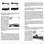
English
Deutsch
The passion pe
www.magura.co
ople
m
Español
Italiano
Nederlands
Français
Workshop
Disc Brakes
DE: Zulässiges Gesamtgewicht für die Bremsscheiben Storm und Storm SL:
EN: Permissible total weight for Storm and Storm SL rotors:
FR: Poids total admissible pour les disques de frein Storm et Storm SL :
NL: Toelaatbaar totaalgewicht voor de remschijven Storm en Storm SL:
IT: Peso totale consentito per i dischi Storm e Storm SL:
ES: Peso total permitido para los discos Storm y Storm SL:
Storm SL
Storm
160/140
160/160
180/160
180/180
203/180
203/203
90kg - XC-Race
100kg
120kg
140kg
150kg
160kg
-
110kg
130kg
150kg
180kg
200kg
Ausstattungsänderungen und Irrtümer vorbehalten.
1
Deutsch
English
Français
Nederlands
Italiano
1. Welcome.......................................................................................................................2
2. Notes about this manual.............................................................................................4
3. Appropriate use...........................................................................................................7
4. Before the first ride.....................................................................................................9
5. Before every ride....................................................................................................... 11
6. After a fall...................................................................................................................14
7. Braking correctly.......................................................................................................16
7.1 Adjusting the brake levers – ergonomics...............................................................16
7.2 Optimum (full) braking – weight shift.....................................................................17
7.3 Prolonged braking.................................................................................................18
7.4 Braking before / in corners....................................................................................18
8. Transport of the bicycle............................................................................................19
9. Installing the brake....................................................................................................20
9.1 Installing the brake levers on the handlebars........................................................21
9.2 Installing the rotor on the wheel.............................................................................22
9.3 Installing the brake calliper on the frame or the fork..............................................23
9.4 Aligning the brake hose.........................................................................................25
10. Shortening the brake hose.....................................................................................26
10.1 Special points about hoses routed in the frame..................................................30
11. Maintenance.............................................................................................................31
11.1 Table for maintenance work.................................................................................31
11.2 Checking and replacing the brake pads...............................................................32
11.2.1 Checking the brake pads.................................................................................32
11.2.2 Replacing the brake pads................................................................................33
11.3 Checking and replacing the rotor.........................................................................35
11.3.1 Checking the rotor...........................................................................................35
11.3.2 Replacing the rotor..........................................................................................35
11.4 Cleaning the brake...............................................................................................36
12. Repair work..............................................................................................................36
13. Bleeding / Filling the brake system.......................................................................37
13.1 Filling and bleeding the brake with the MAGURA Service Kit.............................38
14. Tips...........................................................................................................................43
14.1 Help in dealing with squealing brakes? ..............................................................43
14.2 Brake pads rub – slave pistons extend unevenly................................................43
14.3 Lightweight quick-release skewers?....................................................................44
15. Troubleshooting......................................................................................................45
16. Accessories and tools............................................................................................46
16.1 Adaptor................................................................................................................46
16.2 Further MAGURA accessories and tools . ..........................................................49
17. Guarantee and warranty.........................................................................................50
Español
Contents
1. WelCoMe
Congratulations! You have chosen a fully hydraulic disc
brake from MAGURA. You will be amazed by its awesome braking power and the minimum amount of maintenance that is required. Millions of riders around the world
rely on the stoppers from the Swabian pioneer of hydraulic brakes.
We paid attention to perfected ergonomics as well as
to their functionality in the disc brakes of the very latest
MAGURA MT model series. The force applied by your
hand to produce the movement of the brake level is transferred by a piston in the brake lever mount through a column of mineral oil. The column of mineral oil is moved
towards the brake callipers by the movement of the lever.
This results in the brake pads being pressed from both
sides against the rotor. The friction between the pads and
the rotor slows the bicycle, which also produces heat. The
rotor and callipers become hot!
Never touch either the rotor or the brake callipers after long downhill runs or
prolonged braking as there is a risk of burns!
You will be delighted to discover that disc brakes of the
MAGURA MT model series have an enormous braking
effect even with little hand force being applied while at the
same time being less susceptible to the weather conditions. In wet conditions in particular disc brakes respond
noticeably quicker than rim brakes and have the expected
strong action after just a short time.
The system does not wear the wheel rims, but under certain circumstances, for example, if they have not been installed optimally they can cause squealing noises, mainly
in wet weather conditions.
Please note that there are different versions of the
MAGURA MT model series for various types of installations and disc diameters. Installation is done with various
adaptors, but the basic installation steps are always the
same.
2
In the MAGURA Forum at magura.com you can get free
online help from power users at any time. Stay tuned with
the Passion People!
3
Deutsch
Español
Italiano
Nederlands
Thank you for your confidence in our products, enjoy your
ride and your new MAGURA disc brake!
English
If you still have any questions or if any problems occur,
then we recommend that you visit our homepage www.
magura.com where you can always find up to date information and the hottest tips regarding our products. From
there you can also download this manual as a PDF file in
A4 format.
Français
This manual is a constituent part of the product. Do not
pass on the brake to a new owner without also passing
on this manual. We explicitly reserve the right to make
technical changes and improvements.
2. Notes about this manual
In this manual we have put together for you many tips on
how to use your disc brake and also a great deal of useful
knowledge concerning bicycles in general and their maintenance and care. Please read this manually thoroughly
and to the end. It is worth doing so, even if you having
been riding bicycles all your life. Brake technology in particular has moved forward hugely in recent years. Before
you ride off for the first time with your new MAGURA disc
brake, you should have read at least the two sections
“Appropriate use” and “Before the first ride.”
Before you get onto your bicycle, you should always carry
out the function check described in the section “Before
EVERY ride” so that you will have fun when riding.
Even a manual that is as thick as an encyclopaedia cannot possibly cover every single combination of bicycle
and components that can be found on the market. For
that reason this manual concentrates on your newly purchased MAGURA fully hydraulic disc brake and the most
common components and gives the main information and
warnings.
When you carry out the maintenance and servicing work
that is described in detail, you should always bear in
mind that the instructions and information only apply to
MAGURA fully hydraulic disc brakes.
Note that this manual may need to be supplemented, depending on the experience and/or skill of the person doing
the work. Some kinds of work can require an additional
(special) tool or additional instructions. This manual simply cannot convey to you all the skills of an experienced
bicycle mechanic.
Before you set off, here are a few points that concern us
very much as cyclists: Never set off without a suitable helmet and glasses, and ensure that you are wearing suitable high-visibility clothing for cycling, but at the very least
with close-fitting clothing for your legs plus shoes that are
suitable for the pedal system on your bicycle. Always ride
with care in road traffic and follow the traffic regulations
so that you are not a danger to yourself or to other people.
4
As with any other kind of sport, you can also injure yourself when cycling. When you get onto a bicycle you must
be aware of this danger and accept it. Always bear in mind
that when you are on a bicycle you do not have the safety
facilities of a car such as the ABS anti-blocking system or
an airbag – or a sheet steel car body. For that reason take
suitable care at all times and respect other road users.
Deutsch
English
This book cannot teach you how to ride a bicycle. When
you ride a bicycle, you need to be aware that it is a potentially hazardous activity and that the rider must have his
or her bicycle under control at all times.
Nederlands
Comply with the relevant regulations for the use of bicycles off the road. These regulations differ in each country.
Please treat nature with respect if you are touring through
the woods and fields. Only cycle on marked and paved
paths and roads.
We would first of all like to explain to you the components of your new MAGURA fully hydraulic disc brake.
Unfold the folded front page of this instruction manual.
This illustrates in graphic form the brake lever and mount,
brake calliper and numerous small parts, which are also
described there. Leave this page folded out during reading. This helps you to quickly find that parts that are being
referred to in the text.
Français
Never go cycling when under the influence of medications, drugs or alcohol or if you are tyred. Never allow a
second person to ride on your bicycle and always keep
both hands on the handlebars.
5
Español
Italiano
For your own safety, do not attempt too much. If you are not absolutely certain or if you still have any questions, then please contact your MAGURA
dealer.
note the following symbols on particular:
This symbol indicates a possible danger to life and limb if you do not follow
certain requirements for action or if you do not take the appropriate safety
measures.
This symbol warns you about errors or mistakes that could either cause
harm to the environment or other forms of damage.
This symbol gives information on how to handle the product or else points
out the relevant part of these instructions that requires special attention.
The possible consequences are not always described
again when these symbols are shown.
This is not a set of instructions to allow you to build a bicycle out of individual components, to repair one or to put a
partially assembled bicycle into working order.
This manual is not applicable for anything other than the
fully hydraulic disc brake of the MAGURA MT model series that is shown here.
We reserve the right to make changes to the technical
details with regard to the specifications and illustrations in
this instruction manual.
This manual is subject to European legislation. If a
MAGURA fully hydraulic disc brake is supplied outside
Europe then additional instructions must be provided by
the bicycle manufacturer.
6
The disc brakes of the MAGURA MT model series are
suitable for use on various types of bicycle and have been
approved accordingly. In addition to the various categories of mountain bikes this applies in particular to trekking
and city bikes.
Deutsch
3. APPRoPRIAte use
Storm SL
◄ Rotors with a diameter of 160 mm (front and rear) may
only be used if the total weight of the rider, luggage and
bicycle together is not exceeded. Exact details on the total weight are given in the table on page 8.
Storm
160
Storm SL
◄ Rotors with a diameter of 180 mm (front and rear) may
only be used if the total weight of the rider, luggage and
bicycle together is not exceeded. Exact details on the total weight are given in the table on page 8.
Storm
180
Français
140 160
Nederlands
◄ Rotors with a diameter of 160 mm (front) and 140 mm
(rear) may only be used in the XC race area by experienced riders if the total weight of the rider, luggage and
bicycle together is not exceeded. Exact details on the total weight are given in the table on page 8.
Storm
English
The braking action can be impaired if you do not comply with the following
instructions. This can lead to a total failure of the brake. Risk of accidents!
203
Storm SL
7
◄ Rotors with a diameter of 203 mm (front and rear) may
only be used if the total weight of the rider, luggage and
bicycle together is not exceeded. Exact details on the total weight are given in the table on page 8.
Español
Storm
Italiano
Storm SL
Tips for the selection of the correct rotor diameter and the
rotor version:
◄ MAGURA recommends in principle that the front and
rear rotors are of the same diameter. The majority of the
braking force can be applied to the front brake under optimal full braking conditions on a surface that offers good
grip. However, the rear brake is often used for a longer
period without interruption, especially when riding over
difficult terrain. The danger of overheating is especially
great in such cases. For that reason MAGURA recommends a large rotor here as well.
◄ In the XC race area experienced riders can save
weight by using a rotor at the rear whose diameter is one
size less than that of the front rotor.
◄ In the models MT8 and MT6 MAGURA recommends
the use of Storm rotors instead of the lighter Storm SL
rotors that are supplied as standard so as to increase the
resistance of the braking system to heat (for example, on
longer tours when carrying a lot of luggage).
Permissible total weight for Storm and Storm SL rotors
160/140
160/160
180/160
180/180
203/180
203/203
Storm SL
90 kg – XC race
100kg
120kg
140kg
150kg
160kg
Storm
n/a
110kg
130kg
150kg
180kg
200 kg
8
2. The position of your body is broadly determined by the
type of bicycle. However, various components on your
bicycle have been designed that they can be adjusted
to a certain extent to suit the proportions of your body.
This also includes the brake levers.
In all the brake levers of the MAGURA MT model
series it is possible to adjust their angle to the handlebars and the distance of the lever blade from the
handlebar grips. In certain models it is also possible
to adjust the position of the pressure point (BAT).
You can find further information on this in the section
“Braking correctly.”
3. New brake pads must be “run in” until they produce
optimal braking values. Do this by accelerating the bicycle to around 30 km/h around 30 to 50 times and
braking to a standstill. The “running in” process is
complete when the force that needs to be applied by
your hands for braking does not reduce any further.
4. Always pay attention to your speed if the brake is
being used harder than usual (a total weight of over
100 kg and/or descents) and always brake with both
brakes simultaneously!
5. Depending on the actual model that you have, use
your brakes in accordance with the application profiles given on page 8. Otherwise there is a possibility
of the brake system failing and so resulting in unpredictable dangers to life and limb.
9
Deutsch
English
Français
Under certain circumstances MAGURA disc brakes
can have a much greater braking action than your
previous brake. First of all do some cautious test braking away from normal road traffic on a flat area with a
surface that offers good grip. Gradually increase the
amount of braking force.
Nederlands
Italiano
1. Are you familiar with the hydraulic disc brakes from
MAGURA? Test whether you can operate the front
brake with the same lever (left or right) that you are
used to using. If that is not the case, have the brake
levers swapped over by your MAGURA dealer before
your first ride.
Español
4. Before the first ride
6. Are you familiar with the other components of your
bicycle, such as the gears, the clipless pedals or the
effects of the suspension elements on its riding behaviour? Make yourself thoroughly familiar with the
functions of your bicycle before you set off.
You can find further information in the general instruction manual for your bicycle.
7. Never set off without a suitable helmet and glasses,
and ensure that you are wearing suitable high-visibility clothing for cycling, but at the very least with closefitting clothing for your legs plus shoes that are suitable for the pedal system on your bicycle.
Bear in mind that the braking path can be longer if you have handlebars with
bar ends. The brake lever blades cannot be reached as easily in some grip
positions.
10
Attachments or clamps that have not been done up properly can result in
parts coming away from the bicycle. A hard fall could be the result!
2. Have all the screw connections for the brake system
been done up tightly? Use the Torx T25 key that is
supplied with the brake to do this, but the MAGURA
torque wrench is even better. Note and apply the
specified tightening torques.
3. Carry out a brake test while the bicycle is at a standstill
by squeezing the lever blade towards the handlebars
with two fingers and normal braking force. The brake
lever may not be allowed to reach the handlebar grip!
The pressure point must be stable at once in the
case of disc brakes. If you have not reached the pressure point after two thirds of the travel, then operate
(“pump”) the lever blade several times until the pads
lie against the disc. If the pressure point wanders during a ride, then the brake system must be bled.
4. Hold the lever blade at the pressure point and check
that there are no leaks in all the connections, hoses,
bleed screws and the reservoir.
Deutsch
English
1. Have the quick-release skewers or screw fittings been
closed correctly at the front and rear wheels, the seat
post and other components?
Français
It is essential to check the following before each ride:
Nederlands
5. BEFoRE EVERY RidE
11
Español
Italiano
You can find further information on the topic of “leaks”
in the section “shortening the brake hose.”
5. Check the amount of wear of the brake pads at the
same time, while pressing the lever blade. Do this by
pushing the rear end of the transport device between
the “ears” of the brake pad holders If this test gauge
cannot fit any longer between the “ears” of the pads,
then the brake pads are worn and must be replaced at
once.
You can find further information on the topic of “Changing brake pads” in the section “Maintenance.”
6. Release the lever blade and check whether the wheels
can rotate freely without the rotors rubbing against the
brake pads or the housing of the brake calliper. Check
as applicable to ensure that the wheels are firmly attached.
You can find further information on the topic of “rubbing pads” in the sections “Installing the brake” and
”Tips.”
7. Check that the brake pads and rotors are free of oil,
grease or other lubricants.
Contaminated brake pads and rotors can drastically
reduce the braking power. For that reason always ensure that neither oil no other fluids get into or onto the
brake, for example, when you are cleaning the wheels
or lubricating the chain. Contaminated pads cannot be
cleaned at all and must be replaced! Rotors can be
cleaned with brake cleaner or with warm water that
has a little washing up liquid in it.
You can find further information on the topic of “Replacing brake pads” in the section “Maintenance.”
8. Check the thickness of the rotors. The minimum thickness is printed on the rotors. There may not be less
than this around the entire friction ring. However, if
that ever happens, then the rotor must be replaced at
once.
12
12. In addition, make the check of your bicycle that is recommended by the maker of your bicycle in the operating instructions.
13. Check that you have the complete emergency set in
your touring pack - Torx T25 key, 1 pair brake pads,
transport device, rubber band.
13
Deutsch
Español
Italiano
Never ride if your bicycle is defective in any one of these points! A defective
bicycle can cause severe accidents! If you are not absolutely certain or if
you still have any questions, then please contact your MAGURA dealer.
English
11. Bounce the bicycle on the ground from a low height.
If you hear any odd rattling noises then look for the
cause. Check the bearings and screwed connections
as required.
Français
10. Rotate both wheels freely to check that they are not
out of round or out of alignment. If the wheel is out of
round or misaligned this can lead to tyres rupturing at
the side, broken axles and torn spokes.
Nederlands
9. Are the tyres in a good condition and do both tyres
have enough air in them? You can find the details on
the minimum and maximum pressure (in bar or PSI)
on the side of the tyre.
6. AFtER A FAll
1. Check that the wheels are still properly fastened in
the wheel holders (drop outs) and that the rims are
centred properly in the frame and the forks. Rotate the
wheels and observe the gap between the frame and
the tyres.
You can find further information in the general instruction manual for your bicycle.
Attachments or clamps that have not been done up properly can result in
parts coming away from the bicycle. A hard fall could be the result!
2. Check whether the wheels can rotate freely without
the rotors rubbing against the brake pads or the housing of the brake calliper.
You can find further information on the topic of “rubbing pads” in the sections “Installing the brake” and
”tips.”
3. Are the brake levers still aligned correctly or have they
twisted around the handlebars? If that is the case,
loosen the lower nut, align the brake lever so that it
is correct again, and tighten up the lower nut again as
described in the section “Installing the brake.”
4. Check the brake levers and the lever blades for any
damage or deformation. Check that the brake hoses
are securely attached in the brake levers by tugging
hard on the brake hoses.
5. Carry out a brake test while the bicycle is at a standstill
by squeezing the lever blade towards the handlebars
with two fingers and normal braking force. The brake
lever may not be allowed to reach the handlebar grip!
The pressure point must be stable at once in the
case of disc brakes. If you have not reached the pressure point after two thirds of the travel, then operate
(“pump”) the lever blade several times until the pads
lie against the disc. If the pressure point wanders during a ride, then the brake system must be bled.
14
Deutsch
6. Hold the lever blade at the pressure point and check
that there are no leaks in all the connections, hoses,
bleeding screws and the reservoir.
8. At the end, take a look at the entire bicycle to see if
there have been any deformations, discolorations or
cracks.
English
7. Bounce the bicycle on the ground from a low height.
If you hear any odd rattling noises then look for the
cause. Check the bearings and screwed connections
as required.
15
Español
Italiano
Nederlands
Once you are back home you should check the bicycle again thoroughly.
Any damaged parts must be repaired or replaced. If in doubt, consult your
MAGURA dealer. A defective bicycle can cause severe accidents!
Français
Only continue riding if your bicycle passes all these tests, back again by the
shortest route and very carefully. Avoid sudden acceleration or braking and
do not stand on the pedals. If you have any doubts about the usability of
your bicycle, fetch a vehicle to take it back home instead of taking any risks.
7. BRAKIng CoRReCtlY
7.1 Adjusting the brake levers – ergonomics
The brake levers of the MAGURA MT model series were
designed and have been provided with adjustment options according to the latest research by specialists in
ergonomics and with through extensive test riding and in
practical use. You will get the best possible braking function if the brake lever is set up for the rider, his anatomy
and the position that he takes up when riding the bicycle.
◄ Sit in the saddle and place your hands on the lever
blades. Adjust the angle of the brake levers such that your
fingers are positioned as an extension of your arms. You
can find further information on installing brake levers in
the section “Installing the brake.”
◄ Move the brake lever on the handlebars in such a way
that one or two fingers (whichever you prefer) lie at the
end of the lever blade. If necessary, modify the position
of the gear shift levers so that you can reach them easily.
◄ Set the distance to reach the lever blades with the aid
of the reach adjust screw and a Torx T25 key so that the
first joint of your finger can reach around the lever blade
without needing to pull the lever blade.
Check as well that the pressure point is
reached before the grip area of the lever
blade is parallel to the handlebars.
◄ With the BAT brake levers of the MAGURA MT model
series it is also possible to set the pressure point at which
the brake pads just lie on the rotor to suit your personal
preference. Do this by turning the BAT screw at the brake
lever. Ensure here as well that the lever blade cannot be
pulled right back to the handlebar!
The lever blade may not be allowed to reach the handlebar grip! The full
braking power must have been reached before that. Otherwise the brake
may not be able to provide its full braking force. Risk of accidents! Check
this each time after adjusting the reach distance and/or the BAT screw.
16
Operate both brakes at the same time and bear in mind
that the front brake can transmit more force by far when
on a surface that provides a good grip as a result of the
shift of weight.
Other conditions apply when braking on loose, dirty or wet
surfaces. Here excessive braking of the front wheel can
lead to a skid. For that reason you should practise using
the brakes on different kinds of surfaces.
Get used to your brakes – with care. Practise emergency braking in an area
where there is no traffic until you are sure that you can control your bicycle.
This can prevent accidents.
Wet conditions reduce the braking power and make the wheels skid easily.
Allow for longer braking distances in the rain, reduce your speed and brake
with caution.
Ensure that your brake pads and brake surfaces are absolutely free of wax,
oil and grease. Risk of accidents!
Deutsch
English
Français
In case of such full braking your weight also shifts sharply forwards and the load on the rear wheel is reduced.
Therefore it is more likely on a surface that provides a
good grip for the rear wheel to come up and for the bicycle to pitch forwards end over end than for the wheels to
lose adhesion. This problem becomes more severe when
riding downhill in particular. If you brake with full force you
must therefore attempt to keep your weight as far back
and as low as possible.
Nederlands
You can adapt your speed to suit the terrain and the traffic
conditions with the aid of MAGURA brakes. If required,
MAGURA disc brakes of the MT model series must be
able to bring the bicycle to a standstill as quickly as possible.
Italiano
7.2 optimum (full) braking – weight shift
17
Español
The technology and our knowledge are constantly improving and expanding. Please visit www.magura.com to get the latest information on our products and additional useful tips.
7.3 Prolonged braking
Constant braking without a break, and especially with just
one brake, can lead to a reduction in the action of the
brake or even to the brake failing in extreme situations.
On long descents you should get used to braking with
both brakes, briefly but strongly. Avoid prolonged braking and always release the brake again in between. Stop
at the first signs of possible overheating. Symptoms that
point to overheating are that you need to apply increased
force with your hand or that smells or noises become noticeable. Let the brakes cool down.
The brake pads and rotors wear down as a result of the
friction and all the more quickly if you ride more often over
hilly terrain and in the rain or through dirt. MAGURA disc
brakes have a fully automatic system to compensate for
wear of the pads. This ensures the pressure point of the
brake always remains at about the same position. For that
reason the amount of wear of the brake pads must be
checked before each ride. If necessary, worn brake pads
must be replaced by original spare parts.
Disc brakes get hot when in operation. Therefore never touch the rotors immediately after stopping – and especially not after longer descents.
Ensure that you always have a spare pair of brake pads and a brake pad fitting screw in your emergency set.
7.4 Braking before / in corners
You risk a crash if you ride too fast into a corner. It is
also easy to crash if you only start braking once you have
entered the corner. For that reason you should always
reduce your speed before you go into the corner. Release
the brakes as much as possible on entering the corner
so that the tyres can maintain optimum grip in the corner.
The technology and our knowledge are constantly improving and expanding. Please visit www.magura.com to get the latest information on our products and additional useful tips.
18
◄ Never operate the lever blade if the wheels have been
removed. However, if that has happened and the rotor
can no longer be pushed between the brake pads, then
slowly push back the brake pistons with the transport device while the pads are mounted. Do not use force. If necessary, do this from various angles until the brake pistons
slide back without needing to use excessive force. It is
essential to check that the brake pads do not get dirty or
contaminated, and above all, not with oil or grease.
Deutsch
It is necessary to note the following points regarding the
brake system when transporting your bicycle.
English
8. tRAnsPoRt oF thE BiCYClE
◄ Always insert in place the transport device that is
supplied with the brake into the brake calliper when the
wheels are removed.
◄ Lay the wheels down carefully after removing them so
that the rotors do not get bent or dirty.
◄ Squeeze the lever blade hard and hold it in this position with a strong rubber band.
19
Español
Italiano
◄ You can leave the brake as it is when transporting the
bicycle by air, meaning that you do not need to drain the
hydraulic fluid beforehand.
Nederlands
Never push back the brake pistons without the brake pads in place. The pistons could be damaged!
Français
If the brake pads have been pushed so far together that the transport device
no longer fits in between them, then in an emergency you can press the
brake pads apart with a thin, sharp knife.
9. InstAllIng the BRAKe
● Tools required: Torx T25 key, MAGURA torque wrench
with T25 bit, screwdriver with a broad blade, transport
device.
For your own safety, do not attempt too much in installation and maintenance. If in doubt, leave the work to be done by a MAGURA dealer.
Ensure that the Allen key or Torx key is always inserted fully into the socket
to avoid chewing up the screw heads.
MAGURA has manufactured this brake system in accordance with the usual standards and on the basis of comprehensive testing. MAGURA cannot test every single
possible combination due to the large number of different
forks and frames that could be used. When you install this
brake, please ensure that the brake is compatible with
your bicycle and its components. If you are not absolutely
certain or if you still have any questions, then please contact your MAGURA dealer.
The checking of the suitability of the brake unit for the relevant frame and
fork is to be done by the installer (maker, dealer, but also the user) himself.
He is responsible for the bicycle as an overall product within the meaning of
product liability law. Unsuitable combinations and incorrect installation can lead to
damage and even to accidents!
The lever blades, callipers and hoses are of a completely different design
between MAGURA disc brakes of different model series and years of manufacture. Under no circumstances can you “mix and match” parts between
different models. Risk of accidents!
Ineffective heat removal by the brake calliper into the frame or the forks as a
result of materials that do not conduct heat well (such as carbon fibre) or
components that can only take up a limited amount of heat due to their design can lead to overheating of the brake system. For that reasons never paint over the
brake calliper. Overheating of the brake could lead to a complete failure of the brake in
an extreme case. Risk of accidents!
With disc brakes the heat from the brake callipers can in individual cases
affect the mechanical properties of the materials of the frame and the forks.
Therefore note carefully the details given in the operating instructions of the
manufacturers of the frame and the forks or else consult your bicycle dealer.
20
The brake lever can be installed on the left or right of the
handlebars as desired. All that is necessary is to align
the lever clamp correctly: with the thicker end pointing
upwards. In addition, an arrow is marked on brake lever
clamps made of aluminium and the MAGURA logo must
remain visible.
Deutsch
Nederlands
◄ Place the brake lever on the handlebars, replace the
brake lever clamp and do up the brake lever retaining
nuts by two turns around the fixed bolts. Then do the upper brake lever retaining nut up tightly. Torque: 3 Nm.
English
◄ Completely undo the brake lever retaining nuts and
remove the brake lever clamp.
Français
9.1 installing the brake levers on the handlebars
Only tighten up the lower brake lever retaining nut sufficiently so that it still
allows the brake lever to twist around the handlebars in the event of a fall.
This old motocross trick can save you expensive damage after a fall!
21
Español
Italiano
◄ Last of all, do the lower brake lever retaining nut up
tightly. Maximum torque: 3 Nm.
9.2 Installing the rotor on the wheel
◄ Place the rotor with the letter facing outwards and the
arrow showing the direction of rotation in the direction of
travel on the 6-hole attachment of the hub. Do up the rotor
screws with the Torx T25 key until the rotor can still just
be turned by hand.
◄ Only use original screws or else, if you are reusing the
old screws, before using them you should apply a few
drops of screw locking agent (medium strength, such as
Loctite 243) to the threads.
1
4
6
2
3
◄ Rotate the rotor by hand against the direction of travel to the rear and tighten up the rotor screws with the
MAGURA torque wrench on alternate sides. Screw
torque for steel screws: 4 Nm, torque for aluminium
screws: 3 Nm.
5
Use a magnet to check if they are steel screws (magnetic) or aluminium
screws (non-magnetic).
If you have a so-called “Centerlock” wheel, carefully read through the section “Installing a Centerlock adaptor.”
22
PM mount
◄ Check whether the PM mount or IS mounts in the
frame or fork are free of any remnants of paint and that
the mounting areas have no burrs. If that is not the case,
then please contact your MAGURA dealer.
Working on suspension forks made of magnesium can entail risks regarding
corrosion. Follow the instructions of the maker of the suspension forks. If
the anti-corrosion coat of a suspension fork has been removed, then a suitable medium such as protective paint or clear varnish must be applied.
◄ Install the adaptor if required to the fork or the frame,
using the screws supplied.
Note when doing this the instructions given in the “Adaptors” paragraph in the section “Accessories” regarding
brake callipers. Torque: 6 Nm.
23
Deutsch
English
Français
Never install the brake calliper using adaptors from other makers! MAGURA
shall have no liability whatsoever in such cases of misuse. Only use parts
from MAGURA or from fork or frame manufacturers that have been explicitly
approved for use with MAGURA disc brakes.
Nederlands
Is mount
Italiano
Disc brakes of the MAGURA MT model series are compatible with frames and forks with brake holders in compliance with the IS international attachment standard and
Postmount attachment (PM). Depending on the mounting
standard and rotor diameter, you may require an adaptor. You can find further information on this in the section
“Accessories.” There you can find a table to determine
which brake calliper you require.
Español
9.3 Installing the brake calliper on the frame or the fork
◄ Mount the wheel with the installed rotor into the frame
or the forks and lock the quick-release skewers or the thru
axle in accordance with the instructions of the relevant
maker. Check last of all whether the rims are centred
within the frame or the forks and that the tyres do not rub
when they rotate.
◄ Press apart the brake pads in the brake calliper with
the help of the transport device or the screwdriver and
place the brake calliper on the PM mount in the frame or
fork or into the adaptor. Ensure when you do this that the
rotor sits correctly between the brake pads. Only tighten
up the brake calliper screws enough to ensure that the
brake calliper can still be moved to the side by hand.
◄ Press the brake lever blade several times until the
brake pads lie against the rotor. Hold down the lever
blade. Tighten up the brake calliper retaining screws alternately and in small steps. Torque: 6 Nm.
◄ Release the lever blade and check the alignment of
the brake calliper with respect to the rotor. If the rotor is
not centred within the brake calliper slot then repeat the
mounting process.
◄ Press the lever blade several times while the wheel is
rotating. Then check whether the brake pads are pulled
back from the rotor on both sides and are positioned parallel to it.
24
◄ Route the brake hose along the frame and/or the fork
in the way envisaged by the bicycle maker.
The brake hoses must be at least 2 cm from
the rotor in any riding or suspension position. If that is not the case, then the brake
hose can be damaged by the radiated heat. The brake
could fail. Risk of accidents!
It is essential that you check the routing of the brake hoses before the first
ride. Do this by turning the handlebars as far as they can go to the left and
to the right and ensure that the brake hose neither prevents the full movement of the handlebars nor that it catches on other components. Danger of falling off!
If your bicycle has suspension elements (suspension forks or rear suspension) then test them by moving them as far as you can and checking whether the brake hose is either stretched too much or else contacts or even
catches on other moving parts (cranks, pedals, rotor, etc,). Danger of falling off!
25
Deutsch
English
Français
◄ Align the brake hose so that it runs optimally along the
frame or the fork. Fix the brake hose directly to the hose
connection and do the bleeding screw up tightly with the
MAGURA torque wrench. Torque: 3 Nm.
Nederlands
◄ Loosen the bleeding screw of the RHR hose connection by turning it a maximum of 30°, using the Torx T25
key. The brake hose can now be rotated easily by hand.
Hold the screw in place with the tool while doing this so
that it does not twist.
Italiano
The disc brakes of the MAGURA MT model series (with
the exception of the model MT 2) are equipped with the
innovative RHR hose connection (“Rotatable Hose Routing”) for optimal laying of the brake hoses. These allow
continuous angular adjustment of the brake hose to the
brake calliper without needing to open the brake system
and thus subsequently to refill or bleed it.
Español
9.4 Aligning the brake hose
10. shoRtenIng the BRAKe hose
● Tools required: Torx T25 key, 8 mm open-ended
wrench, MAGURA torque wrench with T25 and 8 mm
bits, screwdriver with a broad blade, MAGURA hose
cutter, plastic hammer, 2 transport devices, mole
wrench (or bench vice)
● Required spare parts: hose insert, olive
◄ Remove the bicycle wheel so that you have free access to the brake calliper. Slowly push the slave pistons
into the brake calliper while the brake pads are mounted,
using the transport device or a screwdriver with a broad
blade. Do not use force. If necessary, do this from various
angles until the slave pistons slide back without needing
to use excessive force.
Never press the slave pistons back like this if the pads have not been installed, otherwise they could be damaged. The brake system may only be
opened once the slave pistons have been pressed back up to the stop.
◄ Undo the lower brake lever retaining nut until the brake
lever can be pointed upwards.
◄ Push the protective cap at the brake lever / hose connection a few centimetres onto the brake hose.
26
◄ Determine the optimal length for the hose while it is not
under tension before you shorten the brake hose. Do this
by fixing the brake hose next to its hose connection at the
brake lever that is pointing vertically upwards so that the
handlebars can still be moved fully to the left and the right.
When the brake lever is brought back later to the correct
position for rising, this produces the required extra length
of hose so that you can still shorten it later if you add a
different accessory or use different handlebars or if the
brake hose is damaged as the result of a fall.
Always route the brake hose from the brake calliper up to the handlebars /
brake lever before you shorten it! This also applies to any brake hoses that
have been routed within the frame.
27
Deutsch
English
Français
Never squeeze the lever blade while the brake system is open.
Nederlands
Professional tip: If you are certain that the brake hose is long enough, you
can cut off the brake hose while it is still mounted, 5 cm from the hose termination.
Italiano
◄ Carefully pull the brake hose out of the brake lever.
Español
◄ Undo the sleeve nut at the brake lever with the 8 mm
open-ended wrench.
◄ Shorten the brake hose with the MAGURA cutter. Always cut the brake hose at right angles and hold it as
close as possible to the point where it will be cut so
that no oil can escape.
Never shorten the MAGURA brake hose at the lower end with the RHR connector! The hose cannot be used any longer without this pressed-in hose
connector!
Never use a saw or pliers or the like to shorten the brake hose!
◄ Clamp the brake hose in the groove of the transport
device that was supplied and fix it with the aid of a second
transport device and a mole wrench (or in a bench vice).
◄ Carefully drive a new hose insert up to the stop in the
brake hose by using the plastic hammer.
◄ Check that the hose insert is right up at the stop in the
hose.
28
Deutsch
◄ Push the sleeve nut and a new olive over the brake
hose. Push the prepared brake hose into the brake lever,
up to the stop.
◄ Turn the sleeve nut two or three turns by hand in the
brake lever.
Français
English
Note that only sleeve nuts with a coarse
thread (silver) may be used for disc brakes
of the MAGURA MT model series.
◄ Press the brake hose into the brake lever until the
sleeve nut is done up tightly. Torque: 4 Nm.
Nederlands
◄ Tighten it up with the 8 mm open-ended wrench.
29
Español
◄ Squeeze the lever blade and check whether the pressure point has been set at the lever. If that is not the case,
then the brake needs to be bled (see the section “Maintenance”). If the pressure point has been set, keep the
lever blade held down and check that the brake hose connections do not leak.
Italiano
◄ Check at once that it has been installed correctly by
trying to pull the brake hose away from the brake lever.
10.1 special points about hoses routed in the frame
◄ Cut the brake hoses off at the top at the brake lever so
that they are as short as possible.
◄ Seal off the open brake hose with a stopper.
Always route the brake hose from the brake assembly up to the handlebars
/ brake lever before you shorten it! This also applies to any brake hoses that
have been routed within the frame.
30
Only use MAGURA ROYAL BLOOD to fill or top up MAGURA disc brakes –
hence no oils from other makers, let alone DOT brake fluid. These can damage the seals and lead to the brakes failing. Risk of accidents!
Brakes that have once been filled incorrectly, i.e. with DOT brake fluid, cannot be serviced any longer. They must be replaced completely. Risk of accidents!
Nederlands
Français
As opposed to DOT brake fluid, the mineral oil used by
MAGURA is also not hygroscopic, meaning that it does
not tend to pick up moisture from the environment and
hence dramatically reduce its boiling point temperature.
This means that the mineral oil in MAGURA disc brakes
does not need to be changed regularly. It can be used for
several years without you needing to worry about your
safety.
Deutsch
◄ MAGURA disc brakes use as the braking medium a
low-viscosity mineral oil (“MAGURA ROYAL BLOOD”)
which does not aggressively attack the skin and eyes, unlike DOT brake fluid (as used in cars, motorcycles and in
a number of other disc brakes for bicycles).
English
11. MAIntenAnCe
31
before every ride
monthly and before a long tour
before every ride
before every ride
if very dirty
not necessary
Español
Check the wear of the pads
Check the wear of the rotors
Check the brake hoses
Check the brake hose connectors
Clean the brakes
Change the brake fluid
Italiano
11.1 table for maintenance work
11.2 Checking and replacing the brake pads
The brake pads in the brake callipers wear down due to
the friction against the rotor. With rim brakes this can be
detected because the amount of travel at the brake lever
becomes greater, MAGURA disc brakes have a fully automatic system to compensate for wear of the pads. This
ensures the pressure point of the brake always remains
at the same position. For that reason the amount of wear
of the brake pads must be checked before each ride. If
necessary, worn brake pads must be replaced by original
spare parts.
Ensure that you always have a spare pair of brake pads and a brake pad fitting screw in your emergency set.
● Tools required: Torx T25 key, MAGURA torque wrench
with T25 bit, screwdriver with a broad blade, transport
device
11.2.1 Checking the brake pads
◄ Squeeze the lever blade while the wheel is still in place
and maintain the pressure.
◄ Check whether the feeler of the transport device can
be inserted between the “ears” of the brake pad holders.
However, if that is not he case, then the rotor must be
replaced at once.
◄ You can also check the brake pads once they have
been removed: The minimum thickness of the pad plus
the holder material is 2.5 mm. Measure the thickness of
the pad at the thinnest point either with a calliper gauge or
use the slot in the transport device as a test gauge.
32
Never press the slave pistons back like this if the pads have not been installed, otherwise they could be damaged.
◄ Undo the brake pad fitting screw with the Torx T25 key.
◄ Remove the brake pads individually upwards out of the
brake calliper.
Deutsch
English
◄ Slowly push the slave pistons back into the brake calliper while the brake pads are mounted, using the transport
device or a screwdriver with a broad blade. Do not use
force. If necessary, do this from various angles until the
slave pistons slide back without needing to use excessive
force.
Français
◄ Remove the wheel so that you have free access to the
brake calliper.
Nederlands
11.2.2 Replacing the brake pads
◄ Insert the new brake pads individually into the brake
calliper. The brake pads must point inwards, towards the
rotor. They are held in position by magnets.
33
Español
◄ Clean the inside of the brake calliper with a dry rag.
Use MAGURA brake cleaner to remove stubborn dirt.
Italiano
Never squeeze the lever blade if the brake pads are not in place.
◄ Tighten up a new pad fitting screw in the brake calliper.
◄ Ensure that this passes between the “ears” of both
brake pad holders.
◄ Do the pad retaining screw up tightly with the MAGURA
torque wrench. Torque: 2.5 Nm.
◄ Mount the wheel back again.
◄ Squeeze the lever blade several times until the pressure point returns to its usual position.
◄ “Run in” the new brake pads as described in the section “Before the first ride.”
Only use original MAGURA brake pads. If you use brake pads from other
manufacturers MAGURA can assume no responsibility or liability whatsoever for the reliable functioning of the brake and you lose all claims under
liability and warranty. Risk of accidents!
Always change both brake pads together. When doing this, use a new brake
pad fitting screw with unused screw locking agent on the thread. In an emergency you can apply a drop of a locking agent (medium strength, such as
Loctite 243) to the thread if you have to use a brake pad fitting screw that has already
been used before.
34
11.3.1 Checking the rotor
Deutsch
The rotors also suffer wear due to the friction of the brake
pads. MAGURA disc brakes have a fully automatic system
to compensate for wear. This ensures the pressure point
of the brake always remains at the same position. For that
reason the amount of wear of the rotors must be checked
each time that the pads are replaced. If necessary, worn
rotors must be replaced by original spare parts. Replace
the pads as well each time that you replace the rotor.
English
11.3 Checking and replacing the rotor
11.3.2 Replacing the rotor
◄ Remove the rotor with the Torx T25 key.
◄ Mount the new rotor as described in the section “Installing the brake.”
35
Nederlands
Italiano
◄ In many cases a thicker base remains on the outside
at the friction ring if the brake calliper had been placed
a little lower. Then the thickness of the rotor cannot be
determined with a conventional calliper gauge. In such a
case go to your MAGURA dealer, who will have suitable
measuring equipment.
Español
◄ Check the thickness of the rotors with a calliper gauge.
Go to a MAGURA dealer if you do not have a suitable tool.
Français
MAGURA rotors have a thickness of 2.0 mm in a new
state. The wear limit is reached if the friction ring (the area
that the brake pads rub against) is only 1.8 mm thick. This
wear limit is also stated on the rotors.
◄ Slowly push the slave pistons back into the brake calliper while the brake pads are mounted, using the transport
device or a screwdriver with a broad blade. Do not use
force. If necessary, do this from various angles until the
slave pistons slide back without needing to use excessive
force.
◄ Mount the wheel with the installed rotor into the frame
or the fork and lock the quick-release skewers or the thru
axle in accordance with the instructions of the relevant
maker.
◄ Squeeze the lever blade several times until the pressure point returns to its usual position.
◄ “Run in” the new rotor as described in the section “Before the first ride.”
11.4 Cleaning the brake
◄ Use MAGURA brake cleaner to remove stubborn dirt
from the brake calliper. Before doing that, remove the
brake pads as described in the section “Changing the
brake pads”.
◄ Clean the rotor with warm water that has a little washing up liquid in it. You can also use MAGURA cleaner here
if the dirt is especially stubborn. Then rinse off the rotor
with plenty of clean water.
Brake pads that have been contaminated with oil or grease cannot be
cleaned. They cannot be used any longer and must be replaced.
12. RePAIR WoRK
MAGURA does not generally carry out any repairs on
disc brakes of the MAGURA MT model series such as
replacing the master or slave pistons or the seals. Defective components are replaced completely in each case
because in such cases it is no longer possible to guarantee that they will work properly. Contact your MAGURA
dealer.
Contaminated brake pads may not be cleaned and used further! Oil and
grease lodge permanently in the pad material so that their friction action is
greatly reduced. In particular, we strongly advise against “insider tips” such
as strong heating. Contaminated brake pads must be replaced at once by new original
brake pads. Risk of accidents!
36
If a new brake hose, brake calliper or brake lever is installed, the brake system must be filled afterwards. If
there is air in the braking system then it needs to be bled
to remove it. Both operations are done in a similar way
and are therefore described together below.
Only use MAGURA ROYAL BLOOD to fill or top up MAGURA disc brakes –
hence no oils from other makers, let alone DOT brake fluid. These can damage the seals and lead to the brakes failing. Risk of accidents!
Brakes that have once been filled incorrectly, i.e. with DOT brake fluid, cannot be serviced any longer. They must be replaced completely. Risk of accidents!
37
Deutsch
Español
Italiano
Ensure when installing a new brake hose that it is compatible with the relevant model of brake. Only use the Disc Tube 2.2 with RHR connection with
the models MT8, MT6 and MT4. The model MT2 may only be used with the
Disc Tube 2.2 with a straight hose connection.
English
As opposed to DOT brake fluid, the mineral oil used by
MAGURA is also not hygroscopic, meaning that it does
not tend to pick up moisture from the environment and
hence dramatically reduce its boiling point temperature.
This means that the mineral oil in MAGURA disc brakes
does not need to be changed regularly. It can be used for
several years without you needing to worry about your
safety.
Français
MAGURA disc brakes use as the braking medium a lowviscosity mineral oil (“MAGURA ROYAL BLOOD”) which
does not aggressively attack the skin and eyes, unlike
DOT brake fluid (as used in cars, motorcycles and in a
number of other disc brakes for bicycles).
Nederlands
13. BlEEdinG / FillinG thE BRAKE sYstEM
13.1 Filling and bleeding the brake with the MAGuRA service Kit
● Tools required: MAGURA Service Kit, 3 mm Allen key,
8 mm open-ended wrench, MAGURA torque wrench
with T25, 3 mm Allen key and 8 mm bits, screwdriver
with a broad blade, transport device, rubber band
◄ Prepare the filling syringe by placing the threaded nipple with the short M6 thread into the transparent hose and
the other end on the syringe. Insert the filling syringe in
the bottle of MAGURA ROYAL BLOOD oil and pull the
handle of the syringe back to fill it. Hold the filling syringe
with the threaded nipple upwards for a few seconds so
that any air in it can escape to the top. Then lightly press
the piston of the filling syringe until all that remains is mineral oil without any air bubbles.
◄ Remove the wheel so that you have free access to the
brake calliper.
◄ Slowly push the slave pistons back into the brake calliper while the brake pads are mounted, using the transport
device or a screwdriver with a broad blade. Do not use
force. If necessary, do this from various angles until the
slave pistons slide back without needing to use excessive
force.
Never press the slave pistons back like this if the pads have not been installed, otherwise they could be damaged.
◄ Undo the brake pad fitting screw with the Torx T25 key.
38
◄ Align the bicycle in a workshop stand so that the PM
“ears” of the brake calliper are exactly vertical above one
another. Then the hose connection is at the highest point
of the brake calliper. This is the only way to ensure
filling without adding air or to completely bleed the
brake calliper.
◄ Undo the lower brake lever fitting screw by 1 or 2 turns.
Deutsch
English
Français
◄ Insert the transport device with the thicker end into the
brake calliper between the slave pistons and hold it in
place with a rubber band.
Nederlands
◄ Remove the brake pads individually upwards out of the
brake calliper.
39
Español
Italiano
◄ Turn the brake lever horizontally and then upwards by
a further 1 cm. Do the brake lever fitting screw up again
a little.
◄ Undo the filling screw at the brake calliper with the
3 mm Allen key.
◄ Then turn the threaded nipple with your fingers until it
is finger-tight in the filling opening of the brake calliper.
Then tighten it up lightly with an open-ended wrench.
Never squeeze the lever blade while the brake system is open.
◄ Undo the upper EBT closure screw at the brake lever
with the Torx T25 key.
◄ Place the attachment of the second filling syringe without piston completely into the upper EBT bleed opening.
Alternatively: Use the “Pro Bleed Kit.”
◄ Carefully press the mineral oil through the brake with
the filling syringe at the brake calliper until the second filling syringe is filled at the brake lever.
40
Place a rag around the brake lever and carefully remove the upper filling
syringe. Close off the syringe with your finger and drain the remaining mineral oil into a suitable container.
◄ Carefully force some more mineral oil into the brake
system with the lower filling syringe until the EBT bleed
hole at the brake lever mount is full to the top.
◄ Do up the EBT closure screw in the EBT bleed hole
by hand and tighten it with the MAGURA torque wrench.
Torque: 0.5 Nm. The EBT screw must be flush with the
mount.
41
Deutsch
English
Français
◄ If there are no longer any air bubbles coming out after carrying out the procedure described above, draw the
mineral oil in to the lower filling syringe until there is only
a small amount of it in the upper filling syringe.
Nederlands
◄ While doing so, squeeze the lever blade slowly several
times and release it suddenly so as to drive out any stubborn air bubbles in the braking system. Alternatively: Use
the “Pro Bleed Kit.”
Italiano
Repeat this process slowly until no more air bubbles appear either at the
brake lever or the brake calliper.
Español
◄ Draw the mineral oil back with the lower filling syringe.
Ensure that there is always sufficient mineral oil in the
upper filling syringe to avoid forcing air into the brake system.
◄ Undo the filling nozzle from the filling opening at the
brake calliper.
◄ Close the filling opening with the filling screw. Torque:
2.5 Nm.
Carefully remove any escaped oil from the
brake lever and the brake calliper with a
clean rag or brake cleaner.
◄ Remove the transport device from the brake calliper.
Install the brake pads, as described in the section “Replacing the brake pads” and install the wheel again.
◄ Carry out a brake test while the bicycle is at a standstill
by squeezing the lever blade towards the handlebars with
two fingers and normal braking force. The lever blade may
not be allowed to reach the handlebar grip! The pressure
point must be stable at once in the case of disc brakes. If
you have not reached the pressure point after two thirds
of the travel, then operate (“pump”) the lever blade several times until the pads lie against the rotor.
◄ If no pressure point has been set you must carefully repeat the filling or bleeding operation as appropriate. If that
still does not help, then contact your MAGURA dealer.
◄ Hold the lever blade at the pressure point and check
that there are no leaks in all the connections, hoses,
bleed screws and the compensating reservoir. Alternatively: Use the “Pro Bleed Kit.”
42
Squealing noises in disc brakes can occur for a number
of reasons and there are also many possible solutions,
so the topic will not be discussed in detail at this point. If
necessary, contact your MAGURA dealer.
The technology and our knowledge are constantly improving and expanding. You can find a lot of tips about problems with squealing disc brakes in
the FAQs section at www.magura.com.
Deutsch
14.1 help in dealing with squealing brakes?
English
14. tIPs
◄ Mount the wheel back again. It is essential that you
leave the brake pads in place, otherwise it could happen
that you pump one of the pistons out of the brake calliper!
Nederlands
● Tools required: 2 mm Allen key (alternatively: 2 mm
thick sheet metal or a used rotor)
Italiano
If the brake pistons at the brake calliper extend by different
amounts, then as a rule the pressure point moves closer
to the handlebars and rubbing noises occur. This problem
can be dealt with by “mobilising” the brake (slave) pistons.
The brake pads centre themselves again with respect to
the rotor and rubbing noises are permanently avoided.
Français
14.2 Brake pads rub – slave pistons extend unevenly
43
Español
Ensure that the tools are clean and, above all, free of oil or grease.
◄ Place the tool between the brake pads and so push
one of the brake pistons back completely. Support both
thumbs on the brake calliper and pull the tool with your
fingers.
◄ Hold the tool in this position and have a helper operate
the lever blade several times until a stable pressure point
is reached. Then release the lever blade.
◄ Now push the other pad back and have the first pad
that had been pushed back “pumped” against the tool in
the same way. Repeat the process six times in each direction.
◄ Now ask your helper to squeeze the lever blade very
lightly until both pads touch the tool, and then hold the
lever blade in this position. Then push both brake pistons
with the tool and using the same movement as before five
times each from stop to stop through the brake calliper.
◄ Push both pads back fully, reinstall the wheel and
press the lever blade several times until a stable pressure
point has been set.
◄ Do some cautious test runs away from normal road
traffic and do some crash stops from 30 km/h to a complete stop to “run in” the brake. As a result the brake pads
centre them themselves with respect to the rotor.
14.3 lightweight quick-release skewers?
MAGURA advises against using lightweight quick-release
skewers for the wheels (with axles made of titanium or
aluminium) in combination with disc brakes. Often the
required clamping forces cannot be reached. As a minimum, this would result in rubbing noises.
The technology and our knowledge are constantly improving and expanding. Please visit www.magura.com to get the latest information on our products and additional useful tips.
44
45
Deutsch
English
Français
Nederlands
Correction
“Run in” the brake (section “Before the
first ride”)
Clean the rotor with alcohol, replace
the pads and run them in
Air in the system
Bleed the brake (section ”Bleeding /
Filling the brake system”)
Correct transport (section “Transport
of the bicycle”)
System leaking
Check the connectors and the brake
hose, replace if necessary and refill the
brake (section ”Bleeding / Filling the
brake system”)
Brake squeals when apNot installed properly, Position the brake calliper correctly
plied
mating surfaces not
(section “Installing the brake”)
parallel to one another Ensure that the installation holes are
free of paint (section “Installing the
brake”)
Not enough tension
Check that the tension of the spokes
is correct! Increase the tension of the
in the spokes of the
wheel quick-release skewers (install
wheel,
wheel quick-release
on the right!)
skewers not tightened
properly
Pads oily
Carelessness
Replace the pads
Rotor oily
Carelessness
Clean with MAGURA Brake Cleaner,
soapy water or alcohol
Wheel cannot be reinThe lever blade was
Always place the transport device
stalled
pulled while the wheel between the pads. Push the pads back
was removed
manually (section “Maintenance”)
The brake makes strange Pads completely worn, Replace the pads (section “Maintenoises and the braking ac- the pad holder mate- nance”), replace the rotors as well if
tion is very rough
rial is wearing down
required
the rotor
Hose leaking or torn
Replace the hose. Refill the brake
(section ”Bleeding / Filling the brake
system”)
Italiano
Problem
Cause
Lack of braking power / no Brake not “run in”
pressure point
Rotor / Pads oily
Español
15. Troubleshooting
16. Accessories and tools
16.1 Adaptor
Disc brakes of the MAGURA MT model series are compatible with frames and forks with brake holders in compliance with the IS international attachment standard and
Postmount attachment (PM). Depending on the mounting
standard and rotor diameter, you may require an adaptor.
Summary table with all the installation standards and rotor diameters, plus the matching adaptors for front and
rear.
QM adaptor summary
(always assuming a Postmount brake calliper)
Installation
standard
Fork
-
IS
n/a
PM6“
n/a
PM7“
n/a
n/a
PM8“
n/a
n/a
n/a
Rear frame
140 mm
n/a
160 mm
QM12
0722 426
QM27
0724 495
Direct,
without QM
18 mm
QM10
0722 424
QM28
0724 496
QM6
0722 322
Direct,
without QM
IS
QM adaptor with part no. for rotor diameter
160 mm
QM11
0722 425
Direct,
without QM
PM5“
Direct,
without QM
PM6“
n/a
PM7“
n/a
n/a
PM8“
n/a
n/a
180 mm
QM12
0722 426
QM6
0722 322
Direct,
without QM
n/a
203 mm
QM5
0722 321
QM7
0722 323
QM6
0724 131
Direct,
without QM
203 mm
QM9
0722 325
n/a
QM7
0722 323
QM26
0724 131
Direct,
without QM
46
For your own safety, do not attempt too much in installation and maintenance. If in doubt, consult your MAGURA dealer.
Deutsch
● Tools required: Torx T25 key or 4 mm Allen key,
MAGURA torque wrench with T25 or 4 mm Allen-keytype bits
English
installing the adaptor on the frame or the fork
Is mount
Working on suspension forks made of magnesium can entail risks regarding
corrosion. Follow the instructions of the maker of the suspension forks. If
the anti-corrosion coat of a suspension fork has been removed, then a suitable medium such as protective paint or clear varnish must be applied.
◄ Install the adaptor if required to the fork or frame, using
the screws supplied. Torque: 6 Nm.
47
Italiano
Nederlands
◄ Check whether the PM or IS mount in the frame or fork
are free of any remnants of paint and that the mounting
areas have no burrs. If that is not the case, then please
contact your MAGURA dealer.
Español
PM mount
Français
Ensure that the Allen key or Torx key is always inserted fully into the socket
to avoid chewing up the screw heads.
◄ After that, install the brake assembly as described in
your MAGURA disc brake manual.
If the frame is outside the tolerances, place spacer washers between the
frame and the adaptor. Use MAGURA 1 mm washers.
If you need to use more than one washer, it is better to use screws of a more
suitable length, i.e. longer.
48
● Bit box
● Pro Bleed Kit
● Pocket Star
49
Español
Italiano
You can find further accessories under www.magura.com
Deutsch
● Service Kit
English
● MAGURA torque wrench
Français
● Rotors
Nederlands
16.2 Further MAGuRA accessories and tools
17. Guarantee and warranty
MAGURA gives a 5 year warranty on the sealing of the brake lever blade and brake calliper if you register your brake online at www.magura.com. Note the red warranty sheet
in the centrefold of this manual.
This warranty does not apply if the brake was damaged for one of the following reasons:
- Incorrect use or damage due to a fall
- Using the brake with parts from another maker
- Changing the surface of the brake by painting or the like
- Any attempt to dismantle the brake
- Making changes to the brake
- Incorrect maintenance
- Damage or loss while being transported
(We recommend that you insure it to its full value if sending it back!)
We wish to explicitly point that a warranty can only honoured if you include the sales
receipt!
TIP: You can register your brake at no charge at www.magura.com, which can bring
you a number of advantages.
50
Sie finden unsere Weltweiten Handelspartner
und Service Center auf Magura.com
Check out our worldwide partners and
service centers on magura.com
Deutschland
MAGURA Bike Parts
GmbH + Co. KG
Eckisstraße 6
D-72574 Bad Urach
phone +49 (0) 7125 96 94 6-0
fax +49 (0)7125 96 94 6-17
[email protected]
USA
MAGURA USA
724 West Clem
62450 Olney, Illinois
phone 6183952200
fax 6183954711
[email protected]
© MAGURA 2012
All rights reserved
Printed in Germany
Edition 2, 03.2012
2600013
ple
ion peo
The pass
gura.com
www.ma
Asia
MAGURA Asia Limited Co
No. 9 Industrial Park 10th Road
40755 Taichung City
Taiwan
phone +886 4 2359 8555
fax +886 4 2359 9910
[email protected]