1
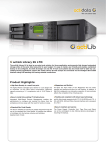
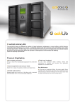
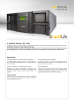
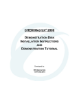
Tape Library 1U, 2U, 4U and 8U
User and Service Guide
1U
2U
4U
8U
actiLib Tape Library – User and Service Guide
Page 1 of 173
Copyright
© Copyright 2010 by actidata. All rights reserved. This item and the information contained herein are the
property of actidata. No part of this document may be reproduce, transmitted, transcript, stored in a retrieval
system, or translated into any language or computer language in any from or by any means, electronic,
mechanical, magnetic, optical, manual, or otherwise, without the express written permission of actidata Storage
Systems GmbH.
Trademark Notices
This document may describe designs for which patents are pending, or have been granted. By publishing this
information, actidata conveys no license under any patents or any other rights.
actidata does not accept liability for errors contained herein or for incidental or consequential damages
(including lost profits) in connection with the furnishing, performance or use of this material whether based on
warranty, contract, or other legal theory. actidata makes no representation or warranties with respect to the
contents of this document and specifically disclaims any implied warranties of merchantability or fitness for any
particular purpose. Further, actidata reserves the right to revise this publication without obligation of actidata to
notify any person or organization of such revision or changes.
Every effort has been made to acknowledge trademarks and their owners. All trademarks within this document
are the property of their respective owners. Trademarked names are used solely for identification or exemplary
purposes, and any omissions are unintentional.
actiLib Tape Library – User and Service Guide
Page 2 of 173
1 Preliminary remarks
1.1
General purpose
This document provides information about installing, operating, troubleshooting, and servicing a
actiLib Tape Library. This document is intended for system administrators and general users who need physical
and functional knowledge of the actiLib Tape Library.
1.2
Contacting actidata Storage Systems GmbH
Europe
actidata Storage Systems GmbH
Wulfshofstraße 16
44149 Dortmund
Germany
Tel. +49 (0) 231-963 632 0
www.actidata.com
1.3
Product warranty caution
The actiLib Tape Library contains no user-serviceable components. Only an authorized service center should
carry out any servicing or repairs.
The warranty for the tape library shall not apply to failures of any unit when:
The tape library is repaired or modified by anyone other than the manufactures personnel or approved agent.
The tape library is physically abused or used in a manner that is inconsistent with the operating instructions
or product specification defined by the manufacturer.
The tape library fails because of accident, misuse, abuse, neglect, mishandling, misapplication, alteration,
faulty installation, modification, or service by anyone other than the factory service center or its approved
agent.
The tape library is repaired by anyone, including an approved agent, in a manner that is contrary to the
maintenance or installation instructions supplied by the manufacturer.
The manufacturer's serial number tag is removed.
The tape library is damaged because of improper packaging on return.
In case of unauthorized repairs or modifications, your warranty becomes immediately void.
actiLib Tape Library – User and Service Guide
Page 3 of 173
General warnings
2 General warnings
DANGER
High voltage
Risk of electric shock
Do not remove cover (or back). No user-serviceable parts are
inside.
Refer servicing to qualified service personnel.
WARNING
Weight of actiLib Tape Library
Risk of personal injury
Before lifting a library:
Observe local health and safety requirements and guidelines for
manual material handling.
Remove all tapes to reduce the weight.
Obtain adequate assistance to lift and stabilize the library during
installation or removal.
Risk of damage to devices
When placing a library into or removing the library from a rack:
Extend the rack’s leveling jacks to the floor.
Ensure that the full weight of the rack rests on the leveling jacks.
Install stabilizing feet on the rack.
Extend only one rack component at a time.
CAUTION
Static sensitive
Risk of damage to devices
A discharge of static electricity damages static-sensitive devices
or micro circuitry.
Proper packaging and grounding techniques are necessary
precautions to prevent damage.
NOTE
Ventilation – Place the product so that its location does not
interfere with proper ventilation.
Heat – Place the product so that its location is away from heat
sources.
Power sources – Connect the product to a power source only of
the type directed in the operating instructions or as marked on
the product.
Power cord protection – Place the AC line cord so that it is not
possible to be walked on or pinched by items placed upon or
against it.
Object and liquid entry – Insure that objects do not fall and
liquids are not spilled into the product’s enclosure.
actiLib Tape Library – User and Service Guide
Page 4 of 173
Contents
3 Contents
1
Preliminary remarks ....................................................................................................................... 3
1.1
1.2
1.3
General purpose ..................................................................................................................... 3
Contacting actidata................................................................................................................. 3
Product warranty caution ....................................................................................................... 3
2
General warnings ............................................................................................................................ 4
3
Contents ........................................................................................................................................... 5
4
Figure ............................................................................................................................................... 8
5
Table ............................................................................................................................................... 13
6
Product overview and features ..................................................................................................... 14
6.1
6.2
6.3
7
Installing ........................................................................................................................................ 25
7.1
7.2
7.3
7.4
7.5
7.6
7.7
7.8
7.9
7.10
7.11
7.12
7.13
7.14
7.15
7.16
7.17
8
Supported configurations ..................................................................................................... 15
Front panel ........................................................................................................................... 16
Rear panel ............................................................................................................................ 19
6.3.1
Power supply ......................................................................................................... 20
6.3.2
Tape drives............................................................................................................. 21
6.3.3
Library controller ................................................................................................... 24
6.3.4
iSCSI bridge (not supported for Mainline) ............................................................ 24
6.3.5
Ethernet port .......................................................................................................... 24
Location requirements ......................................................................................................... 25
SCSI requirements ............................................................................................................... 26
7.2.1
SCSI host bus adapter (HBA) ................................................................................ 26
7.2.2
LUN scanning ........................................................................................................ 27
7.2.3
Serial attached SCSI (SAS) ................................................................................... 27
Fibre channel requirements .................................................................................................. 28
Preparing the host ................................................................................................................ 30
Installing precautions ........................................................................................................... 30
Unpacking the library .......................................................................................................... 31
Identifying the product components..................................................................................... 31
Removing the shipping lock ................................................................................................ 32
Rack mounting the library.................................................................................................... 33
Installing a tape drive ........................................................................................................... 35
Installing the library controller ............................................................................................ 37
Installing a power supply ..................................................................................................... 38
Connecting the cables .......................................................................................................... 39
7.13.1 Connecting the power cord .................................................................................... 39
7.13.2 Connecting the parallel SCSI cable ....................................................................... 39
7.13.3 Connecting the FC cable ........................................................................................ 40
7.13.4 Connecting the SAS cable ..................................................................................... 41
7.13.5 Connecting the Ethernet cable and a USB device .................................................. 41
Verifying the host ................................................................................................................ 42
Powering up/down the library .............................................................................................. 42
Tape cartridges ..................................................................................................................... 42
7.16.1 Tape cartridge type ................................................................................................ 42
7.16.2 Using and maintaining tape cartridges ................................................................... 44
7.16.3 Labeling tape cartridges ......................................................................................... 45
7.16.4 Write-protecting tape cartridges............................................................................. 46
Magazines ............................................................................................................................ 47
7.17.1 Slot numbering scheme .......................................................................................... 47
7.17.2 Mail slot ................................................................................................................. 48
Operating ....................................................................................................................................... 49
8.1
Operator control panel (OCP) .............................................................................................. 49
actiLib Tape Library – User and Service Guide
Page 5 of 173
Contents
8.2
8.3
8.4
8.5
8.6
8.7
9
8.1.1
Operating Modes.................................................................................................... 49
OCP Philosophy..................................................................................................... 49
8.1.2
8.1.3
Moving media within the library ........................................................................... 50
8.1.4
Cleaning tape drives ............................................................................................... 50
8.1.5
Releasing and replacing magazines ....................................................................... 50
1U Operator control panel (OCP) ........................................................................................ 51
8.2.1
Power-Up Display.................................................................................................. 51
8.2.2
Note about the LED’s ............................................................................................ 51
8.2.3
Input modes (OCP Navigation) ............................................................................. 52
8.2.4
Power ON/OFF ...................................................................................................... 52
8.2.5
Menu flow charts ................................................................................................... 53
2U, 4U Operator control panel (OCP) ................................................................................. 67
8.3.1
Power-Up Display.................................................................................................. 67
8.3.2
Note about the LED’s ............................................................................................ 67
8.3.3
Input Modes ........................................................................................................... 69
8.3.4
Power ON/OFF ...................................................................................................... 69
8.3.5
Menu flow charts ................................................................................................... 70
8U Operator control panel (OCP) ........................................................................................ 77
8.4.1
Navigation menu .................................................................................................... 77
8.4.2
Navigation dialog (8U) .......................................................................................... 78
8.4.3
General behaviour (8U) ......................................................................................... 79
8.4.4
Home screen .......................................................................................................... 79
8.4.5
Main menu functions ............................................................................................. 80
8.4.6
Menu flow charts (8U) ......................................................................................... 100
Remote management unit (RMU) ...................................................................................... 106
8.5.1
Overview.............................................................................................................. 106
8.5.2
Operations through the RMU ............................................................................... 106
8.5.3
Status icons as shown by the RMU ...................................................................... 107
8.5.4
Login .................................................................................................................... 107
8.5.5
Identity ................................................................................................................. 108
8.5.6
Status ................................................................................................................... 109
8.5.7
Configuration ....................................................................................................... 112
8.5.8
Operations ............................................................................................................ 120
8.5.9
Service ................................................................................................................. 121
Partitioning the library ....................................................................................................... 124
8.6.1
Drive naming ....................................................................................................... 124
8.6.2
Mixing of drives................................................................................................... 125
8.6.3
SCSI element addressing ..................................................................................... 127
8.6.4
Element reporting ................................................................................................ 128
Default settings .................................................................................................................. 129
Troubleshooting........................................................................................................................... 130
9.1
Installation problems .......................................................................................................... 130
9.1.1
SCSI ID ................................................................................................................ 130
9.1.2
SCSI host adapter installation .............................................................................. 130
9.1.3
LUN scanning ...................................................................................................... 130
9.1.4
SCSI cabling ........................................................................................................ 130
9.1.5
Termination.......................................................................................................... 131
9.1.6
Compatibility ....................................................................................................... 131
9.1.7
Backup application installation ............................................................................ 131
Device driver installation ..................................................................................... 131
9.1.8
9.2
Troubleshooting table ........................................................................................................ 132
9.3
Removing tape cartridges from the library ........................................................................ 136
9.4
Emergency release ............................................................................................................. 137
9.5
Upgrade the library firmware ............................................................................................. 138
9.6
General diagnostic ............................................................................................................. 138
9.6.1
System test ........................................................................................................... 138
9.6.2
Slot-to-Slot test .................................................................................................... 138
9.6.3
Library verify test ................................................................................................ 138
9.7
Error codes ......................................................................................................................... 139
9.7.1
Error messaging ................................................................................................... 139
actiLib Tape Library – User and Service Guide
Page 6 of 173
Contents
9.7.2
9.7.3
9.7.4
9.7.5
9.7.6
9.7.7
10
Error structure ...................................................................................................... 140
OCP error reporting ............................................................................................. 140
RMU error reporting ............................................................................................ 140
Main error codes .................................................................................................. 141
Sub error codes related to the robotic .................................................................. 151
Sub error codes related to the library ................................................................... 153
Servicing ....................................................................................................................................... 154
10.1
10.2
10.3
10.4
10.5
10.6
10.7
10.8
10.9
10.10
Possible tools needed ......................................................................................................... 154
Electrostatic discharge ....................................................................................................... 154
Removing a tape drive ....................................................................................................... 155
Replacing a tape drive ........................................................................................................ 155
Removing the library controller ......................................................................................... 156
Replacing the library controller ......................................................................................... 156
Removing a power supply.................................................................................................. 157
Replacing the power supply ............................................................................................... 157
Servicing a magazine ......................................................................................................... 158
Removing the base chassis ................................................................................................. 158
10.10.1 Preparing to remove the base chassis ................................................................... 158
10.10.2 Removing the base chassis from the rack ............................................................ 159
10.11 Replacing the base chassis ................................................................................................. 159
11
Packaging before transportation ............................................................................................... 160
12
Technical specifications .............................................................................................................. 163
12.1
12.2
12.3
13
Hardware specifications ..................................................................................................... 163
Operating environment ...................................................................................................... 164
Maximum storage capacity and data transfer rate .............................................................. 165
Agency certifications ................................................................................................................... 167
13.1
13.2
13.3
13.4
13.5
13.6
13.7
Recycling and disposal ...................................................................................................... 167
Device standards ................................................................................................................ 168
CE mark ............................................................................................................................. 168
ETL mark ........................................................................................................................... 168
GS mark ............................................................................................................................. 169
FCC (United States) ........................................................................................................... 169
Canadian verification ......................................................................................................... 170
14
Glossary........................................................................................................................................ 171
15
Index ............................................................................................................................................. 172
actiLib Tape Library – User and Service Guide
Page 7 of 173
4 Figure
Figure 1
1U front panel ................................................................................................................................. 16
Figure 2
2U front panel ................................................................................................................................. 16
Figure 3
4U front panel ................................................................................................................................. 16
Figure 4
8U front panel ................................................................................................................................. 18
Figure 5
Library rear panel (1U) ................................................................................................................... 19
Figure 6
Library rear panel (2U and 4U) ....................................................................................................... 19
Figure 7
Library rear panel (8U) ................................................................................................................... 19
Figure 8
Power supply (1U) .......................................................................................................................... 20
Figure 9
Power supply (2U) Figure 10 Power supply (4U, 8U) ................................................................... 20
Figure 11
SCSI HH tape drive ........................................................................................................................ 21
Figure 12
SCSI FH tape drive ......................................................................................................................... 21
Figure 13
SAS HH tape drive.......................................................................................................................... 21
Figure 14
SAS HH tape drive with Ethernet port ............................................................................................ 21
Figure 15
SAS HH tape drive with two SAS connectors ................................................................................ 22
Figure 16
SAS FH tape drive .......................................................................................................................... 22
Figure 17
SAS FH tape drive with two SAS connectors ................................................................................. 22
Figure 18
FC HH tape drive ............................................................................................................................ 22
Figure 19
FC FH tape drive ............................................................................................................................. 23
Figure 20
FC FH tape drive with Ethernet port ............................................................................................... 23
Figure 21
Library controller ............................................................................................................................ 24
Figure 22
Ethernet port ................................................................................................................................... 24
Figure 23
Fibre channel topology (LN Port) ................................................................................................... 28
Figure 24
Fibre channel topology (L Port) ...................................................................................................... 28
Figure 25
Fibre channel topology (N Port) ..................................................................................................... 28
Figure 26
Remove the yellow label ................................................................................................................. 32
Figure 27
Remove the shipping lock ............................................................................................................... 32
Figure 28
Replace the yellow label ................................................................................................................. 32
Figure 29
Install the rack rails (1U) ................................................................................................................ 33
Figure 30
Install the mounting brackets (1U) .................................................................................................. 34
Figure 31
Secure the library to the rack (1U) .................................................................................................. 34
Figure 32
Pullout tab for product ID (4U) ....................................................................................................... 35
Figure 33
Install a tape drive (4U) .................................................................................................................. 36
Figure 34
Install a library controller (4U) ....................................................................................................... 37
Figure 35
Install a power supply (4U) ............................................................................................................. 39
actiLib Tape Library – User and Service Guide
Page 8 of 173
Figure 36
Connect the SCSI cable .................................................................................................................. 40
Figure 37
Connect the terminator .................................................................................................................... 40
Figure 38
Connect the FC cable ...................................................................................................................... 40
Figure 39
Power up/down the library (4U) ..................................................................................................... 42
Figure 40
Proper barcode label placement ...................................................................................................... 45
Figure 41
Write-protecting a tape cartridge .................................................................................................... 46
Figure 42
Slot numbering scheme (1U) .......................................................................................................... 47
Figure 43
Slot numbering scheme (2U – Single mail slot) ............................................................................. 47
Figure 44
Slot numbering scheme (2U – Triple mail slot) .............................................................................. 47
Figure 45
Slot numbering scheme (4U) .......................................................................................................... 48
Figure 46
Slot numbering scheme (8U) .......................................................................................................... 48
Figure 47
Home screen (OCP - 1U) ................................................................................................................ 51
Figure 48
Menu symbol key (OCP - 1U) ........................................................................................................ 53
Figure 49
Main menu (OCP - 1U)................................................................................................................... 54
Figure 50
Information menu (OCP - 1U) ........................................................................................................ 55
Figure 51
Library information menu (OCP - 1U) ........................................................................................... 56
Figure 52
Drive information menu (OCP - 1U) .............................................................................................. 57
Figure 53
Inventory menu (OCP - 1U)............................................................................................................ 58
Figure 54
Commands menu (OCP - 1U) ......................................................................................................... 59
Figure 55
Configuration menu (OCP - 1U) ..................................................................................................... 60
Figure 56
Configuration menu, continuation (OCP - 1U) ............................................................................... 61
Figure 57
Drive configuration menu (OCP - 1U)............................................................................................ 62
Figure 58
Service menu (OCP - 1U) ............................................................................................................... 63
Figure 59
Library service menu (OCP - 1U) ................................................................................................... 64
Figure 60
Drive service menu (OCP - 1U) ...................................................................................................... 65
Figure 61
Drive FW Upgrade menu (OCP - 1U) ............................................................................................ 66
Figure 62
Home screen (OCP - 2U, 4U) ......................................................................................................... 67
Figure 63
Main menu (OCP - 2U, 4U) ............................................................................................................ 70
Figure 64
Information menu 1 of 2 (OCP - 2U, 4U) ....................................................................................... 71
Figure 65
Information menu 2 of 2 (OCP - 2U, 4U) ....................................................................................... 72
Figure 66
Commands menu (OCP - 2U, 4U) .................................................................................................. 73
Figure 67
Configuration menu (OCP - 2U, 4U) .............................................................................................. 74
Figure 68
Service menu 1 of 2 (OCP - 2U, 4U) .............................................................................................. 75
Figure 69
Service menu 2 of 2 (OCP - 2U, 4U) .............................................................................................. 76
Figure 70
OEM Skin (OCP - 8U) .................................................................................................................... 77
Figure 71
Status Screen (OCP - 8U) ............................................................................................................... 77
actiLib Tape Library – User and Service Guide
Page 9 of 173
Figure 72
Navigation menu (OCP - 8U) ......................................................................................................... 78
Figure 73
Open Mailslot(s) (OCP - 8U) .......................................................................................................... 80
Figure 74
Status – Library or Drive(s) (OCP - 8U) ......................................................................................... 80
Figure 75
Information menu (OCP - 8U) ........................................................................................................ 82
Figure 76
Network General (OCP - 8U) ......................................................................................................... 83
Figure 77
General Library Identity (OCP - 8U) .............................................................................................. 84
Figure 78
Drive X Identity (OCP - 8U)........................................................................................................... 84
Figure 79
Inventory menu – Drives and Magazines (OCP - 8U) .................................................................... 86
Figure 80
View License keys (OCP - 8U)....................................................................................................... 87
Figure 81
Commands Main Menu (OCP - 8U) ............................................................................................... 87
Figure 82
Unlock magazine dialog (OCP - 8U) .............................................................................................. 87
Figure 83
Reinventory (OCP - 8U) ................................................................................................................. 88
Figure 84
Move Media (OCP - 8U) ................................................................................................................ 88
Figure 85
Configuration Main Menu (OCP - 8U) ........................................................................................... 89
Figure 86
Restore Lib Config (OCP - 8U) ...................................................................................................... 90
Figure 87
Add License Key (OCP - 8U) ......................................................................................................... 90
Figure 88
Logical Library (OCP - 8U) ............................................................................................................ 91
Figure 89
Library Settings (OCP - 8U) ........................................................................................................... 91
Figure 90
Drive X Configuration (OCP - 8U) ................................................................................................. 92
Figure 91
Network IPvX (OCP - 8U).............................................................................................................. 93
Figure 92
Set access Pin (OCP - 8U) .............................................................................................................. 94
Figure 93
Restore Defaults (OCP - 8U) .......................................................................................................... 94
Figure 94
Set Date and Time (OCP - 8U) ....................................................................................................... 95
Figure 95
Save Library Config (OCP - 8U) .................................................................................................... 95
Figure 96
Service Main Menu (OCP - 8U) ..................................................................................................... 96
Figure 97
View logs and Detailed view for one entry (OCP - 8U) ................................................................. 96
Figure 98
Service Library and Detailed view for one entry (OCP - 8U) ......................................................... 97
Figure 99
Service Library samples (OCP - 8U) .............................................................................................. 98
Figure 100
Information menu (OCP - 8U) ...................................................................................................... 100
Figure 101
Commands menu (OCP - 8U) ....................................................................................................... 101
Figure 102
Configuration menu 1 of 2 (OCP - 8U) ........................................................................................ 102
Figure 103
Configuration menu 2 of 2 (OCP - 8U) ........................................................................................ 103
Figure 104
Service menu 1 of 2 (OCP - 8U) ................................................................................................... 104
Figure 105
Service menu 2 of 2 (OCP - 8U) ................................................................................................... 105
Figure 106
RMU Login ................................................................................................................................... 107
Figure 107
Library identity (RMU) ................................................................................................................. 108
actiLib Tape Library – User and Service Guide
Page 10 of 173
Figure 108
Drive identity (RMU) ................................................................................................................... 108
Figure 109
Network identity (RMU) ............................................................................................................... 109
Figure 110
Library status (RMU) .................................................................................................................... 110
Figure 111
System status (RMU) - 2 examples depending on configuration .................................................. 110
Figure 112
Drive status (RMU)....................................................................................................................... 111
Figure 113
Tape cartridge inventory (RMU) .................................................................................................. 112
Figure 114
System Configuration (RMU) ....................................................................................................... 112
Figure 115
Logical Libraries (RMU) .............................................................................................................. 114
Figure 116
License key (RMU)....................................................................................................................... 114
Figure 117
Drive configuration (RMU) .......................................................................................................... 114
Figure 118
Network configuration (RMU) ..................................................................................................... 115
Figure 119
SNMP (RMU) .............................................................................................................................. 116
Figure 120
User settings (RMU) ..................................................................................................................... 117
Figure 121
Date/time (RMU) .......................................................................................................................... 118
Figure 122
Error Log mode (RMU) ................................................................................................................ 119
Figure 123
Event for Email Notification (RMU) ............................................................................................ 119
Figure 124
Factory defaults (RMU) ................................................................................................................ 119
Figure 95
Move media (RMU) ...................................................................................................................... 120
Figure 126
Media Inventory (RMU) ............................................................................................................... 121
Figure 127
Release magazines (RMU)............................................................................................................ 121
Figure 128
Library diagnostics (RMU) ........................................................................................................... 121
Figure 129
Drive diagnostics (RMU) .............................................................................................................. 122
Figure 130
Firmware (RMU) .......................................................................................................................... 122
Figure 131
Reboot the library (RMU) ............................................................................................................. 123
Figure 132
Library logs (RMU) ...................................................................................................................... 123
Figure 133
Clean a tape drive (RMU) ............................................................................................................. 124
Figure 134
Cartridge Memory (RMU) ............................................................................................................ 124
Figure 135
1-Partition-System (drives and correlated magazines) .................................................................. 125
Figure 136
2-Partition-System (drives and correlated magazines) .................................................................. 126
Figure 137
3-Partition-System (drives and correlated magazines) .................................................................. 126
Figure 138
4-Partition-System (drives and correlated magazines) .................................................................. 127
Figure 139
Removing a stuck tape (8U).......................................................................................................... 136
Figure 140
Rear panel (access holes) .............................................................................................................. 137
Figure 141
4U Front panel (magazine remove)............................................................................................... 137
Figure 142
4U OCP Error display ..................................................................................................... 140
Figure 143
RMU Error display ......................................................................................................... 140
actiLib Tape Library – User and Service Guide
Page 11 of 173
Figure 142
Remove a tape drive...................................................................................................................... 155
Figure 143
Remove the library controller ....................................................................................................... 156
Figure 144
Remove the power supply ............................................................................................................. 157
Figure 145
Product ID label ............................................................................................................................ 160
Figure 146
Packaging the library (1U and 2U) ............................................................................................... 161
Figure 147
Packaging the library (4U) ............................................................................................................ 161
Figure 148
Packaging the library (8U) ............................................................................................................ 162
Figure 149
WEEE symbol ............................................................................................................................... 167
Figure 150
CE mark ........................................................................................................................................ 168
Figure 151
ETL mark ...................................................................................................................................... 168
Figure 152
GS mark ........................................................................................................................................ 169
Figure 153
FCC mark ...................................................................................................................................... 169
actiLib Tape Library – User and Service Guide
Page 12 of 173
5 Table
Table 1
Supported configurations ................................................................................................................ 15
Table 2
General front panel overview .......................................................................................................... 17
Table 3
Additional front panel overview (8U) ............................................................................................. 18
Table 4
Power supply overview ................................................................................................................... 20
Table 5
SCSI tape drive overview only till LTO 4 Gen ............................................................................... 21
Table 6
SAS tape drive overview ................................................................................................................ 22
Table 7
FC tape drive overview ................................................................................................................... 23
Table 8
Location requirements .................................................................................................................... 25
Table 9
Tape cartridge type ......................................................................................................................... 43
Table 10
Backward compatibility (tape cartridge) ......................................................................................... 43
Table 11
Library Status .................................................................................................................................. 81
Table 12
Drive X Status ................................................................................................................................. 82
Table 13
Network General and IPvX (information menu) ............................................................................. 83
Table 14
General Library Identity (information menu) ................................................................................. 84
Table 15
Drive X (information menu) ........................................................................................................... 86
Table 16
Inventory Magazines (information menu)....................................................................................... 86
Table 17
Move Media (commands menu) ..................................................................................................... 89
Table 18
Library dialog (configuration menu) ............................................................................................... 92
Table 19
Drives (configuration menu) ........................................................................................................... 92
Table 20
Network IPvX (configuration menu) .............................................................................................. 93
Table 21
Set Access PIN (configuration menu) ............................................................................................. 94
Table 22
Service library (service menu) ........................................................................................................ 98
Table 23
Service drive dialogs (service menu) .............................................................................................. 99
Table 24
Legend of status icons (RMU) ...................................................................................................... 107
Table 25
Default settings ............................................................................................................................. 129
Table 26
Troubleshooting table ................................................................................................................... 135
Table 27
Error codes .................................................................................................................................... 150
Table 28
Packaging the library (1U, 2U and 4U) ........................................................................................ 162
Table 29
Packaging the library (8U) ............................................................................................................ 162
Table 30
Hardware specifications ................................................................................................................ 163
Table 31
Operating environment ................................................................................................................. 164
Table 32
Maximum storage capacity and data transfer rate ......................................................................... 166
Table 33
Device standards ........................................................................................................................... 168
actiLib Tape Library – User and Service Guide
Page 13 of 173
6 Product overview and features
The actiLib Tape Library provides a compact, high capacity, low-cost solution for simple, unattended data
backup.
The actiLib Tape Library is compatible with most operating systems and environments with the appropriate
interface card. However, the library requires either direct support from the operating system or a compatible
backup application to take full advantage of its many features.
Particular emphasis of the actiLib family includes:
Platform of the tape libraries - independent of tape and drive form factors
Configurability - from entry level cost optimized library to a feature rich configuration
Broad level of connectivity – SCSI, FC and SAS depending upon installed tape drives
Expandability – following devices can be added in the field
o
All unit highs:
magazines and tape drives
o
2U, 4U and 8U:
extra library controller, iSCSI bridge
o
2U, 4U and 8U:
Library Extension Module
o
4U and 8U:
extra power supply
Technology upgrade - customer can upgrade tape drive technologies (e.g. LTO5 to LTO6) in the field
Service friendly design – following devices are accessible for quick replacement
All unit heights:
magazines, from the front of the library
tape drives, from the back of the library
2U, 4U and 8U
library controller, power supply and extender from the back of the library
Maximum up time - through advanced error handling and recovery capability
The actiLib family includes the following features:
The library occupies one SCSI target address and uses separate LUNs for the tape drive and library robotics.
USB interface to enable serviceability features (library and drive firmware upgrades) and/or customized
features (storage on demand) implementation
The library can be operated via the front operator control panel (OCP) over the network via the intregal
remote management unit (RMU) or via the storage interface connection by the host application.
Supports industry standard management protocols such as SNMP( SMI-S future development)
Mail slot for import/export of cartridges during library operation
Robotic with barcode reader
The actiLib Tape Library encompasses rack formats for all unit highs. (1U, 2U, 4U 8U).
The actiLib Tape Library encompasses tabletop functionality for 1U, 2U and 4U libraries.
actiLib Tape Library – User and Service Guide
Page 14 of 173
6.1
Supported configurations
For maximal supported configurations, see Table 1.
Tape library
Form factor
(unit high)
1U
2U
4U
8U
Magazine
2
2
4
8
Mail slot
0, 1
0, 1
0, 3
0, 3
Tape slot
8
24
48
96
Half-height drive
1
2
4
4
Full-height drive
0
1
2
4
Power supply
1
1
2
2
Library controller
1
1
1
1
iSCSI bridge
0
1
2
2
--
--
72 slot
4 drives
96 slot
6 drives
144 slot
6 drives
120 slot
4 drives
144 slot
6 drives
Magazines
Tape drives
Other devices
Library extension module (max. slot and drives)
1U
--
--
2U
--
--
4U
--
8U
--
Table 1
72 slot
4 drives
120 slot
4 drives
--
Supported configurations
actiLib Tape Library – User and Service Guide
Page 15 of 173
6.2
Front panel
The front panel of the actiLib Tape Library is used to access the power button, operator control panel (OCP), left
and right magazines, LED’s, and the mail slots.
Figure 1
1U front panel
Figure 2
2U front panel
Figure 3
4U front panel
actiLib Tape Library – User and Service Guide
Page 16 of 173
Number
Description
1
Air vents
2
Power button
Pressing the button will initiate a controlled power down of the library (soft power down)
3
LED <READY> (green)
is illuminated during power on; blinking during tape or library robotics activity.
4
LED <CLEAN> (amber)
is illuminated when the tape drive has determined that a cleaning tape should be used.
Cleaning is only necessary when the library directs to do so. Additional cleaning is not
necessary.
5
LED <ATTENTION> (amber)
is illuminated when the library has detected a condition that requires attention by the
operator.
6
LED <ERROR> (amber)
is illuminated when an unrecoverable tape drive or library error occurs.
A corresponding error message is shown on the LCD screen.
7
<CANCEL> button []
is used to cancel a user action and return to the last menu item.
8
<PREVIOUS> button [◄]
is used to navigate backward through menu items.
9
Right magazine with mail slot (only in 8U library)
10
Right magazines
11
<ENTER> button []
is used to enter to a sub menu or execute an action.
12
<NEXT> button [►]
is used to navigate forward through menu items.
13
Operator control panel (OCP) consisting of 128 x 64 characters.
The OCP displays actions and status information, menu items or error messages equivalent to
the operation mode.
14
Left magazine with mail slot
15
Left magazines
Table 2
General front panel overview
actiLib Tape Library – User and Service Guide
Page 17 of 173
Figure 4
8U front panel
For general front panel overview, see Table 2, Page 17.
Letter
Description
A
B
Table 3
I
<UP> button [▲]
is used to navigate through menu items.
II
<RIGHT> button [►]
is used to navigate through menu items.
III
<DOWN> button [▼]
is used to navigate through menu items.
IV
<LEFT> button [◄]
is used to navigate through menu items.
V
<ENTER> button []
is used to enter to a sub menu or execute an
action.
Window front panel
Additional front panel overview (8U)
actiLib Tape Library – User and Service Guide
Page 18 of 173
6.3
Rear panel
The rear panel of the actiLib Tape Library provides access to the drive interface connectors, the power
connector, Ethernet, serial and USB ports and the magazine release holes. All libraries support parallel SCSI,
SAS and Fibre channel tape drives.
The position of the appended devices on the rear panel is in all libraries common. The power supply is on the left
side, tape drives are in the middle and the library controller is on the right side of the library.
Figure 5
Library rear panel (1U)
Figure 6
Library rear panel (2U and 4U)
Figure 7
Library rear panel (8U)
Number
Description
Number
Description
1
Power supply
A
Storage location (for the shipping lock)
2
Tape drive(s)
B
USB port (Firmware upgrades, key
storage)
3
Pull-out tab
containing the product
information. (Serial Number
/Model/Customer on demand)
C
iSCSI bridge (2U 1x /4U 1x or 2x)
optional possible
4
Library controller
actiLib Tape Library – User and Service Guide
Page 19 of 173
6.3.1 Power supply
The power supply model utilized is dependent on the library model. The part# can be found in the price list.
For a 1U library, see Figure 8.
For a 2U library, see Figure 9
For a 4U or 8U library, see Figure 10.
Figure 8
Power supply (1U)
Figure 9
Power supply (2U)
Number
Description
Figure 10
Number
Power supply (4U, 8U)
Description
1
Fan vent
4
LED (blue)
is illuminated when the AC power is
connected.
2
Storage location (for the shipping
lock)
5
LED (amber)
is illuminated when a fan failure occurs.
The fan is running too slow or is
defective.
3
Power connector
The library requires a 110 / 220 V
AC power connection.
6
LED (green)
is illuminated when the power supply is
producing good power for the library.
Table 4
Power supply overview
actiLib Tape Library – User and Service Guide
Page 20 of 173
6.3.2 Tape drives
SCSI connectors till LTO 4 Generation
Figure 11
SCSI HH tape drive
Figure 12
SCSI FH tape drive
Number
Number
Description
1
Magazine release holes
3
68-pin HD SCSI connectors
2
Fan vent
4
Tape drive LED
Table 5
SCSI tape drive overview only till LTO 4 Gen
SAS connectors all LTO Generations
Figure 13
SAS HH tape drive
Figure 14
SAS HH tape drive with Ethernet port
actiLib Tape Library – User and Service Guide
Page 21 of 173
Figure 15
SAS HH tape drive with two SAS connectors
Figure 16
SAS FH tape drive
Figure 17
SAS FH tape drive with two SAS connectors
Number
Number
Description
1
Magazine release holes
5
LED <ERROR> (amber)
2
Ethernet port
(service/diagnostics not used)
6
Fan vent
3
LED <READY> (green)
7
Tape drive LED
4
SAS connector(s)
Table 6
SAS tape drive overview
Further details can be found on the Internet searching for HP / IBM drive.
FC connectors all LTO Generations
Figure 18
FC HH tape drive
actiLib Tape Library – User and Service Guide
Page 22 of 173
Figure 19
FC FH tape drive
Figure 20
FC FH tape drive with Ethernet port
Number
Number
Description
1
Magazine release holes
4
Ethernet port
(service/diagnostics not used)
2
Fan vent
5
Tape drive LED
3
FC connectors
Table 7
FC tape drive overview
actiLib Tape Library – User and Service Guide
Page 23 of 173
6.3.3 Library controller
Number
Figure 21
Description
1
Ethernet port (RMU connection)
2
Serial port (Engineering Diagnostics)
3
Controller LED blinking ok; if not failure
4
USB port (Firmware upgrades, key
storage)
Library controller
6.3.4 iSCSI bridge (not supported for Mainline)
The iSCSI bridge creates an interface between a network, which utilizes the Ethernet protocol, and peripherals
which utilize a SAS bus architecture. The internal circuitry of the Bridge acts as a two-way interface converting
the data packets, received from the network, into data transfers and electrical signals that storage devices such as
tape drives understand on the SAS bus. Details see iSCSI User Manual.
The iSCSI bridge supports:
* 2U actiLib Tape Library with up to two SAS drives.
* 4U actiLib Tape Library with up to four SAS drives. To support three or four drives the library requires two
iSCSI bridges!
* User management interface via network.
* NTP
* iSNS
* Multi path
6.3.5 Ethernet port
The Ethernet port is only available on the library controller drives and will connect the library to a network / PC
for working with the RMU. On some LTO5/6 tape it is available for service/diagnostics (not used).
Number
Figure 22
Description
1
LED (amber)
is illuminated when a connection is in
place
2
LED (green)
is illuminated when the connection is
ready / in use
Ethernet port
actiLib Tape Library – User and Service Guide
Page 24 of 173
7 Installing
This chapter provides instructions for installing the actiLib Tape Library.
7.1
Location requirements
Choose a location that meets the following criteria:
Criteria
Definition
Rack requirements
Standard 19-inch rack with an appropriate # of U’s (unit high) of clearance
Room temperature
10-35º C (50-95º F)
Power source
AC power voltage: 100-127 VAC; 200-240 VAC
Line frequency: 50-60 Hz
Place the library near to an AC outlet.
The AC power cord is the libraries main AC disconnect device and must be easily
accessible at all times.
Air quality
Place the library in an area with minimal sources of particulate contamination.
Avoid areas near frequently used doors and walkways, stacks of supplies that
collect dust, printers, and smoke-filled rooms.
Excessive dust and debris can damage tapes and tape drive.
Humidity
20-80 percent RH non-condensing
Clearance
Back: Minimum of 15.4 cm (6 inches)
Front:
Minimum of 30.8 cm (12 inches) – for mail slot
Minimum of 60 cm to remove magazines (24 inches)
Sides: Minimum of 5.08 cm (2 inches)
Table 8
Location requirements
For further information, see Chapter Technical specifications 12.
actiLib Tape Library – User and Service Guide
Page 25 of 173
7.2
SCSI requirements
The actiLib Tape Library incorporates a wide SCSI low-voltage differential (LVD) SCSI bus, but may also be
attached to a single-ended (SE) SCSI bus.
Make sure your SCSI host adapter or controller supports these standards.
NOTE
Do not connect any LTO SCSI device to a SE SCSI bus, as it
will severely degrade performance.
The actiLib Tape Library is not compatible with a standard
differential (Diff) or a high-voltage differential (HVD) SCSI
bus.
The library is compatible with a narrow (50-pin) SCSI bus using
a 68-pin to 50-pin adapter that terminates the unused 18 pins.
This adapter is not included with the library and sometimes
labeled high-byte termination.
7.2.1 SCSI host bus adapter (HBA)
To get optimum performance from your actiLib Tape Library you need a SCSI bus that can transfer data at a rate
that supports the libraries maximum burst transfer speed.
For further information, see Chapter Maximum storage capacity 12.3.
If the host computer will have multiple parallel SCSI devices, you must decide how they will be configured into
one or more parallel SCSI busses.
A parallel SCSI bus consists of the host bus adapter (HBA), the parallel SCSI devices, the parallel SCSI cables,
and the terminators. The HBA and devices are connected in a chain, with each device connected to the next. The
last device must have a SCSI terminator. Each device in the chain must have a unique SCSI address (SCSI ID).
An HBA might have one or two channels, with each channel supporting one parallel SCSI bus. Check to see how
many channels the HBA has and what devices are already connected to the HBA. Some devices, such as parallel
SCSI disk drives, could be inside the server.
The devices on a parallel SCSI bus share bandwidth so be careful about which devices you put together on a bus.
NOTE
If you connect the library to an SE SCSI bus, or if there are SE
devices attached to the same SCSI bus, the libraries performance
is limited to the maximum data transfer speed and maximum
cable lengths of the SE SCSI bus. For these reasons, do not use a
SE SCSI bus with the library.
If there is any SE devices on the same SCSI bus, the entire SCSI
bus will negotiate down to SE speed, severely degrading
performance.
The HBA also has a SCSI address that is typically 7. Verify that
each device on the bus has a unique SCSI address. If the preconfigured SCSI address will not be unique on a bus, you will
need to change the SCSI address of one or more of the tape
drives during the installation process.
actiLib Tape Library – User and Service Guide
Page 26 of 173
7.2.2 LUN scanning
The actiLib Tape Library uses a single SCSI ID per tape drive to control the tape drive (LUN 0) and library
robotic (LUN 1).
NOTE
The library requires an HBA that supports LUN scanning. If
LUN scanning is disabled, your host system will not scan
beyond LUN 0 and will fail to discover the library. It will just
see the tape drive.
Some HBAs, such as RAID controllers do not support LUN
scanning.
7.2.3 Serial attached SCSI (SAS)
Serial Attached SCSI (SAS) is a computer bus technology mainly used to transfer data to and from storage
devices, including disk drives and tape drives. SAS is designed to transfer data at up to 6 gigabits per second.
SAS uses serial connections, with a direct connection between the host server and each of the storage devices.
This eliminates the need to configure SCSI busses and assign SCSI IDs, as is required for parallel SCSI devices.
Most SAS HBA ports have four SAS channels. A tape drive uses one channel, so each HBA port can support up
to four tape drives. You can use a cable with one connector on each end, but only one channel will be used.
NOTE
The library has a mini-SAS connector on each SAS tape drive.
Mini-SAS connectors are keyed.
A SAS tape drive is identified by a unique identifier called a World Wide Name (WWN) or World Wide
Identifier (WWID). The library assigns the WWID to the drive bay. When a tape drive is replaced, the WWID is
re-assigned to the new tape drive.
The operating system tracks the WWID for the tape drive on each HBA channel. Each of the drive connectors on
the fan-out cable is associated with an HBA channel. Once a tape drive has been plugged in, it should remain on
the same channel to retain the association between the HBA channel and WWID.
actiLib Tape Library – User and Service Guide
Page 27 of 173
7.3
Fibre channel requirements
Fibre channel (FC) allows an active intelligent interconnection scheme, called a Fabric , to connect devices.
Everything between the ports on FC is called the Fabric. The Fabric is most often a switch or series of switches
that takes the responsibility for routing.
The library allows the selection of the following Fibre Channel port behaviors:
LN Port (default setting) – an automatic configuration that tries arbitrated loop first, then switched Fabric.
Figure 23
L Port – arbitrated loop
Figure 24
Fibre channel topology (LN Port)
Fibre channel topology (L Port)
N Port – point to point protocol in a switched Fabric topology
Figure 25
Fibre channel topology (N Port)
actiLib Tape Library – User and Service Guide
Page 28 of 173
The Fibre channel tape drive can be connected directly to the server with a host bus adapter (HBA) or through a
storage area network (SAN).
NOTE
Use an appropriate HBA for your tape drive due to performance
requirements.
A lower Gb HBA might result in performance degradation when
backing up highly compressible data to a higher Gb tape drive.
In a SAN installation, all switches between the host and the must
be of the appropriate type.
A lower Gb switch in the path may result in performance
degradation. Configure zoning so only the backup servers may
access the library.
actiLib Tape Library – User and Service Guide
Page 29 of 173
7.4
Preparing the host
CAUTION
Static sensitive
Risk of damage to devices
A discharge of static electricity damages static-sensitive devices
or micro circuitry.
Proper packaging and grounding techniques are necessary
precautions to prevent damage.
See Chapter Electrostatic discharge, chapter 10.2.
Follow these general guidelines:
Make sure that your backup application supports the selected HBA and tape drive interface type HBA.
Check with a system administrator, if the host server is connected to a network, before power off.
Install a suitably rated HBA.
Make sure that LUN scanning is enabled on the SCSI host adapter.
7.5
Installing precautions
Adhere strictly the following steps to install the actiLib Tape Library:
WARNING
Weight of actiLib Tape Library
Risk of personal injury
Before lifting a library:
Observe local health and safety requirements and guidelines for
manual material handling.
Remove all tape cartridges to reduce the weight.
Obtain adequate assistance to lift and stabilize the library during
installation or removal.
Risk of damage to devices
When placing a library into or removing the library from a rack:
Extend the rack’s leveling jacks to the floor.
Ensure that the full weight of the rack rests on the leveling jacks.
Install stabilizing feet on the rack.
Extend only one rack component at a time.
NOTE
Do not expose the library to moisture.
Use the library on a firm level surface free from vibration.
Do not place anything on top of the library.
actiLib Tape Library – User and Service Guide
Page 30 of 173
Unpacking the library
7.6
Before unpacking the library, clear a work surface to unpack the library. Select an open rack location allowing
easy access to the host server and an easily accessible power outlet.
NOTE
If the temperature in the room where the library will be installed
varies by 15º C (30º F) from the room where the library was stored,
allow the library to acclimate to the surrounding environment for at
least 12 hours before unpacking it from the shipping container.
Unpacking the actiLib Tape Library:
1.
Before opening and removing the tape library from the box, inspect the container for shipping damage.
If you notice any damage, report it to the shipping company immediately.
2.
Open the box.
3.
Carefully remove the shipping materials from the top of the library.
4.
Remove the accessory package and set aside. (if included)
5.
Remove the two rack rails and set aside. (if included)
6.
Lift the library out of the carton and remove the bag from the loader.
Save the packaging materials for future use.
NOTE
Do not place the library on either end or sides as this may damage
the library.
Identifying the product components
7.7
Confirm that you received the following:
1.
actiLib Tape Library
2.
Library documentation
Optional components, depending on the ordered configuration:
1.
Terminator (Only parallel)
2.
Cables, for instance SCSI, SAS and / or Ethernet cables
3.
Power cord
4.
Rack mount kit:
2 rack mount rails
1 bag of eight M6 screws for the rack mounting (9.5 mm square holes in the rack column)
1 bag of eight M6 screws for rack mounting (6.85 mm round holes in the rack column)
2 mounting brackets
M3x6 torx screws to fix the mounting brackets (amount depending on the unit form factor)
M5 screws to secure the mounting brackets to the rack (amount depending on the unit form factor)
actiLib Tape Library – User and Service Guide
Page 31 of 173
Required additional equipment for a successful installation:
7.8
1.
Ethernet cable(s)
2.
SCSI, SAS or FC cable(s) depending upon drives selected
3.
Terminator(s)
4.
Power cord to match main connector
5.
#2 Phillips screwdriver
Removing the shipping lock
NOTE
The shipping lock, which prevents the robotic transport mechanism
from moving during shipment, must be removed before the library
is powered on.
You may skip this step for an 8U library, no shipping lock is
utilized on the 8U.
To remove and store the shipping lock:
1.
Remove the yellow label that is securing the shipping lock on the top of the library.
Figure 26
2.
Remove the shipping lock.
Figure 27
3.
Remove the yellow label
Remove the shipping lock
Store the shipping lock (in case of returning the unit see chapter 11 replacement is required).
For a 1U library, see Figure 5, Page 19.
For a 2U or 4U library, see Figure 6, Page 19.
4.
Replace the yellow label on the top of the library.
Figure 28
Replace the yellow label
actiLib Tape Library – User and Service Guide
Page 32 of 173
Rack mounting the library
7.9
NOTE
First, read the Chapter Installing precautions, Page 30.
The rack rail components are optional accessories depending on the
ordered configuration.
Skip this chapter, when the rack rail components not available.
Required tools:
#3 Phillips screwdriver
T10 torx screwdriver
Rack mounting the library:
The steps to install a library in a rack are for all unit highs common. In the following figures, a 1U library is
shown as an example.
1.
Determine the location and in the rack for the library to be installed.
2.
Use a pencil to mark the location on each vertical rail in the rack.
3.
In the rack mount kit are two sets of eight M6 screws. Determine the type of rack then choose the
appropriate type of M6 screws.
4.
Secure one rail to each side of the rack in your chosen rack location with a #3 Phillips screwdriver. Insure
the rails are mounted level and at the same rack height on each side.
5.
Secure both the front and back of each rack rail to the rack.
Figure 29 Install the rack rails (1U)
actiLib Tape Library – User and Service Guide
Page 33 of 173
6.
Install the mounting brackets of the library using the Torx screwsT10 included in the rack mount kit;
see Figure 30.
Figure 30 Install the mounting brackets (1U)
7.
Slide the library onto the rack rails.
8.
Secure the library to the rack using a 3# Phillips screwdriver placed through the small holes in the mounting
bracket to tighten the M5 screw(s) on each side of the library.
Figure 31 Secure the library to the rack (1U)
actiLib Tape Library – User and Service Guide
Page 34 of 173
7.10
Installing a tape drive
A tape drive is installed from the rear of the library.
If the library does not already have the tape drive(s) installed, install the tape drive(s) now. If the library already
has tape drives installed additional tape drives may be added after the installation of the library is complete.
Required tool:
#2 Phillips screwdriver
To install tape drives:
1.
Locate an appropriate vacant drive bay on the rear panel of the library.
1U library:
There is only one bay for 1 half-high tape drive.
2U library:
There is only bay space for either 1 full-high or 2 half-high tape drives. Always install the first tape
drive in the bottom drive bay. If the first device is a half-high tape drive, you may install an additional
half-high tape drive in the top bay. If only one half height drive is installed you must install the block
off plate over the upper empty drive position.
4U and 8U library:
Install the first tape drive in the bottom drive bay. Install each additional tape drive in the drive bay
directly above the existing tape drives.
2.
If available, loosen the screws of the drive bay cover and remove the screws by holding the cover in place.
3.
Remove one drive bay cover to install a half-height tape drive; remove two drive bay covers to install a fullheight tape drive.
4.
Slightly pull out the pull-out tab for the product ID label so it does not interfere with the tape drive, see
Figure 32
Figure 32 Pullout tab for product ID (4U)
5.
Before installing the tape drive, inspect the connectors on the tape drive. Ensure that the connectors are
intact, free of any foreign objects, and have no cracks or deformed or bent contacts.
actiLib Tape Library – User and Service Guide
Page 35 of 173
6.
Insert the tape drive into the drive bay, and align the connectors on the library while supporting the drive,
see Figure 33, Step 1.
Figure 33 Install a tape drive (4U)
7.
Push the tape drive into the drive bay until the tape drive seats itself against the back of the library.
8.
Slightly push the pull-out tab for the product ID label back into library, see Figure 33, Step 2.
9.
Tighten the blue captive screws with your fingers to secure the tape drive to the library.
actiLib Tape Library – User and Service Guide
Page 36 of 173
7.11
Installing the library controller
The library controller is installed from the rear of the library.
If the library does not already have a library controller installed, install the library controller now.
Required tool:
#2 Phillips screwdriver
To install a library controller:
1.
Locate the appropriate vacant library controller bay on right side on the rear panel of the library,
shown in Chapter Rear panel 6.3.
2.
If available, loosen the screws of the library controller bay cover and remove the screws by holding the
cover in place.
3.
Before installing the library controller, inspect the connectors on the library controller. Ensure that the
connectors are intact, free of any foreign objects, and have no cracks or deformed or bent contacts.
4.
Insert the library controller on the alignment rails and push the library controller into the library controller
bay until it seats itself against the back of the library, see Figure 34.
(In the following figure, a 4U library is shown as an example.)
Figure 34 Install a library controller (4U)
5.
Tighten the blue captive screws with your fingers to secure the library controller to the library.
actiLib Tape Library – User and Service Guide
Page 37 of 173
7.12
Installing a power supply
NOTE
Skip this chapter for a 1U library, because a power supply is already
installed and no user serviceably part.
Verify that the power to the library is off and the power cord is not
attached
The power supply is installed from the rear of the library.
If the 2U, 4U or 8U library does not have a power supply installed, install the power supply in the bottom left
power supply bay now.
The 4U or 8U library may be configured for a redundant power by installing a second power supply now.
Required tool:
#2 Phillips screwdriver
To install a power supply:
6.
Locate the power supply bay on the left side of the rear panel of the library,
shown in Chapter Rear panel 6.3.
2U library:
There is only 1 power supply bay.
4U and 8U library, There are 2 power supply bays:
Always install:
Install the first power supply in the bottom left power supply bay. The unit can run with one power
supply
If redundant power supplies are desired for fault tolerance install a second
Install a redundant power supply in the power supply bay directly above the existing power supply.
Both supplies must be plugged in the AC mains to operate in failover mode.
7.
If available, loosen the screws of the power supply bay cover and remove the screws by holding the cover in
place.
8.
Before installing the power supply, inspect the connectors on the power supply. Ensure that the connectors
are intact, free of any foreign objects, and have no cracks or deformed or bent contacts.
9.
Insert the power supply on the alignment rails and push the power supply into the power supply bay until it
seats itself against the back of the library, see Figure 35.
(In the following figures, a 4U library is shown as an example.)
actiLib Tape Library – User and Service Guide
Page 38 of 173
Figure 35 Install a power supply (4U)
10. Tighten the blue captive screws with your fingers to secure the power supply to the library.
7.13
Connecting the cables
7.13.1 Connecting the power cord
DANGER
High voltage
Risk of electric shock
Use only approved power cords.
Observe local health and safety requirements and guidelines for
manual material handling.
WARNING
Usage of not approved power cords
Risk of personal injury
Risk of damage to devices
Before connecting a power cord to the library:
Ensure that the power cord meets individual country specific
safety.
Use a sufficient conductor amp capacity to avoid overheating the
library.
The manufacturer disclaims all liability in the event a nonmanufacturer approved power cord is used.
To connect the power cord to the library:
1.
Plug the power cord into the power connector (AC connector) on the rear panel of the power supply, see
Chapter Power supply, Page 20.
2.
Plug the power cord into the power outlet of the power supply.
7.13.2 Connecting the parallel SCSI cable
NOTE
Use only cables and terminators specified for your LTO SCSI tape
drive or labelled as multimode.
To connect the parallel SCSI cable to the tape drive:
1.
Power down the host server before attaching new devices to the library.
2.
Attach one end of the parallel SCSI cable to one of the connectors on the rear panel of the tape drive.
actiLib Tape Library – User and Service Guide
Page 39 of 173
Figure 36 Connect the SCSI cable
3.
Attach the terminator to the remaining parallel SCSI connector on the back panel of the tape drive if the
library is the last or only device on the parallel SCSI bus. Otherwise, attach one end of a parallel SCSI cable
to the remaining port and the other end to the next device on the parallel SCSI bus.
Figure 37 Connect the terminator
4.
Make sure the last device on the parallel SCSI bus is properly terminated.
7.13.3 Connecting the FC cable
NOTE
Use only cables specified for your LTO FC tape drive.
Each FC tape drive has two FC ports.
Cable <Port A> only.
Configure <Port B> for <Auto Detect> on <Fibre Speed> and
<Port Type>.
To connect the FC cable to the tape drive:
1.
Remove the FC port caps if necessary. Attach one end of the FC cable to <Port A> on the tape drive.
Figure 38 Connect the FC cable
2.
Attach the other end of the FC cable to a switch or HBA.
actiLib Tape Library – User and Service Guide
Page 40 of 173
7.13.4 Connecting the SAS cable
NOTE
Use only cables specified for your LTO SAS tape drive.
Each SAS tape drive has a mini-SAS connector.
Mini-SAS connectors are keyed.
Do not force a SAS cable’s mini-SAS connector into the tape
drive mini-SAS connector because it might be keyed differently.
SAS signal rates require clean connections and a minimum number
of connections between the HBA and the library.
Do not use adapters or converters between the HBA and the
library.
A maximum SAS cable length of six meters is recommended.
To connect the SAS cable to the tape drive:
1.
Plug the HBA end of the SAS cable into the connector on the HBA.
If you have a SAS fan-out cable, the end of the cable with only one connector, should be plugged into
the connector on the HBA.
If you are using a cable with a single connector on each end, plug the other end into the connector on
the tape drive.
If you are using a SAS fan-out cable, plug one mini-SAS connector into the connector on each tape
drive. The unused ends of the SAS fan-out cable are single channel and not suitable for use with disk
arrays. Use the other ends to connect tape drives, or coil and secure them to the rack to minimize stress
on the connectors.
7.13.5 Connecting the Ethernet cable and a USB device
To connect the Ethernet cable to the library:
The connection to the Ethernet network is via an industry stand RJ45 copper interface on the rear panel of the
library. The Ethernet connection is used to access the library RMI over the network.
To connect the library to the Ethernet network, inset the Ethernet cable into the Ethernet port of the library, see
Chapter Library controller 6.3.3. When the plug is in the correct position, a click should be heard.
To connect the USB device to the library:
The USB port is on the rear of the library. It can be used for FW upgrades / Skin file updates via OCP see
Chapter Library controller 6.3.3.
actiLib Tape Library – User and Service Guide
Page 41 of 173
7.14
Verifying the host
Depending on the server configuration, you may need to change the SCSI ID of the library.
When the host server is powered on, install the software and/or driver(s) that are compatible with the library.
Backup software packages may require additional software or licensing to communicate with the library
robotics.
To confirm the host server’s operating system recognized the library, consult the operating system
documentation.
7.15
Powering up/down the library
Press the power button on the front bezel to power up/down the actiLib Tape Library. The powering up can take
a few minutes including scanning the inventory and configuration (e.g. drives installed)
In the following figure, a 4U library is shown as an example.
Figure 39
7.16
Power up/down the library (4U)
Tape cartridges
Before you begin using the library, an understanding of the media type, use, maintenance, and how to properly
label and write-protect your tape cartridges will help you to prolong the life of your tape cartridges as well as the
library.
7.16.1 Tape cartridge type
The tape cartridge types supported depend on the drive types installed. The library will support any type of LTO
data cartridge and cleaning cartridge the installed LTO drive will support.
Tape drive generation
LTO2
Tape cartridge type
Ultrium LTO2, 200 GB data cartridge
Universal cleaning cartridge, (50 cleans)
actiLib Tape Library – User and Service Guide
Page 42 of 173
LTO3
Ultrium LTO3, 400 GB data cartridge
Universal cleaning cartridge, (50 cleans)
LTO4
Ultrium LTO4, 800 GB data cartridge
Universal cleaning cartridge, (50 cleans)
LTO5
Ultrium LTO5, 1,6 TB data cartridge
Universal cleaning cartridge, (50 cleans)
Ultrium LTO6, 3,2 TB data cartridge
Universal cleaning cartridge, (50 cleans)
LTO6
Table 9
Tape cartridge type
LTO1
tape drive
LTO2
tape drive
LTO3
tape drive
LTO4
tape drive
LTO5
tape drive
LTO6
tape drive
LTO1 media
Read / Write
Read / Write
Read only
Incompatible
Incompatible
Incompatible
LTO2 media
Incompatible
Read / Write
Read / Write
Read only
Incompatible
Incompatible
LTO3 media
Incompatible
Incompatible
Read / Write
Read / Write
Read only
Incompatible
LTO4 media
Incompatible
Incompatible
Incompatible
Read / Write
Read / Write
Read only
LTO5 media
Incompatible
Incompatible
Incompatible
Incompatible
Read / Write
Read / Write
LTO6 media
Incompatible
Incompatible
Incompatible
Incompatible
Incompatible
Read / Write
Table 10
Backward compatibility (tape cartridge)
Some tape drives include support for both rewriteable and WORM data cartridges. Write-Once, Read-Many
(WORM) data cartridges provide an enhanced level of data security against accidental or malicious alteration of
data on the tape cartridge. The WORM data cartridge can have new data appended to the maximum full capacity
of the tape cartridge, but the user will be unable to erase or overwrite any data previously recorded to the
cartridge.
actiLib Tape Library – User and Service Guide
Page 43 of 173
7.16.2 Using and maintaining tape cartridges
NOTE
Do not degauss Ultrium LTO data cartridges! These data
cartridges are pre-recorded with a magnetic servo signal. This
signal is required in order to use the cartridge with Ultrium LTO
tape drives.
Keep Ultrium LTO cartridges separated from strong magnetic
fields such as computer monitors, electric motors, speakers, or
X-ray equipment.
Exposure to electromagnetic energy or magnetic fields can
destroy data and the embedded servo code written on the media
by the cartridge manufacturer, which can render the cartridge
unusable.
Before you use the library to ensure the longest possible life for your data cartridges, follow these guidelines:
Use only the data cartridges that are designated for your model of the library
Clean the tape drive when the <Clean Drive> LED is illuminated. Be sure to use only Ultrium universal
cleaning cartridges.
Do not drop a LTO data cartridge. Excessive shock can damage the internal contents of the tape cartridge, or
the tape cartridge case itself, making that tape cartridge unusable.
Do not expose your data cartridges to direct sunlight or sources of heat, including portable heaters and
heating ducts.
The operating temperature range for your data cartridges is 10 to 35º C. The storage temperature range is -40
to +60º C in a dust-free environment in which relative humidity is always between 20 percent and 80
percent (non-condensing).
If the data cartridge has been exposed to temperatures outside the ranges specified above, stabilize the
cartridge at room temperature for the same amount of time it was exposed to extreme temperatures or 24
hours, whichever is less.
Place identification labels only in the designated area on the tape cartridge. Labels placed in other areas can
cause operation problems and the tape to become stuck in the drive.
actiLib Tape Library – User and Service Guide
Page 44 of 173
7.16.3 Labeling tape cartridges
Attaching a barcode label to each tape cartridge enables the library and application software to identify the tape
cartridge quickly, thereby speeding up inventory time. Make it a practice to use bar code labels on your tape
cartridges.
Your host software may need to keep track of the following information via the associated barcode:
Date of format or initialization
Tape’s media pool
Data residing on the tape
Age of the backup
Errors encountered while using the tape cartridge (to determine if the tape cartridge is faulty).
NOTE
The misuse and misunderstanding of bar code technology can result
in backup and restore failures. To ensure that your bar codes meet
manufactures quality standards, always purchase them from an
approved supplier and never print bar code labels yourself.
Ultrium tape cartridges have a recessed area located on the front of the cartridge next to the write-protect switch.
Use this area for attaching the adhesive-backed bar code label. Only apply labels as shown in Figure 40.
Figure 40
Proper barcode label placement
NOTE
The bar code label should only be applied with the alphanumeric
portion facing to the left- side of the tape (toward the write protect
switch, see below table #3) and within the marked Barcode label
area.
Never apply multiple labels onto a cartridge, as extra labels can
cause the cartridge to jam in a tape drive.
actiLib Tape Library – User and Service Guide
Page 45 of 173
7.16.4 Write-protecting tape cartridges
All rewritable data cartridges have a write-protect switch to prevent accidental erasure or overwriting of data.
Before loading a cartridge into the library, make sure the write-protect switch on the front of the cartridge is in
the desired position, see Figure 41.
Slide the switch to the right to write-protect the cartridge. A small pad-lock is visible indicating that the
cartridge is write-protected.
Slide the switch to the left to allow the Library to write data to the cartridge.
Figure 41
Number
Description
1
Insertion arrow
2
Barcode label
3
Write-protect switch
4
Write-protected
5
Write-enabled
Write-protecting a tape cartridge
actiLib Tape Library – User and Service Guide
Page 46 of 173
7.17
Magazines
The actiLib Tape Library makes use of removable magazines in each model. Tape cartridges are stored in
magazines. Magazines may be removed and inserted individually. Magazines are locked to prevent unauthorized
removal when inserted in the library and unlock Magazine access may become password protected. For safety
reasons, the robotic motion is stopped whenever when a magazine is removed from the library..
The magazines can be unlocked using the Operator Control Panel (OCP) or the Remote Management Unit
(RMU).
OCP, see Chapter Releasing and replacing magazines, Page 50
RMU, see Chapter Releasing and replacing , Page 121
In case the OCP or RMU initiated process has failed or the library no longer has power a manual emergency
release is available, see Chapter Emergency release, Page 137.
7.17.1 Slot numbering scheme
NOTE
In the following figures an asterisk (*) and the red circle indicates
the mail slots.
Figure 42
Slot numbering scheme (1U)
Figure 43
Slot numbering scheme (2U – Single mail slot)
Figure 44
Slot numbering scheme (2U – Triple mail slot) only with special magazine
actiLib Tape Library – User and Service Guide
Page 47 of 173
Figure 45
Slot numbering scheme (4U)
Figure 46
Slot numbering scheme (8U)
7.17.2 Mail slot
Mail slots are used to import/export individual tape cartridges without interrupting the library operation. The
command to open the mail slot may be denied if the robotics is busy with some operation. In that case “Busy“ is
displayed on the OCP and the command has to be repeated once the robotics operation is finished.
The 1U library provides in the bottom left position a single mail slot magazine (slot 1).
The 2U library provides in the bottom left position a single (slot 1) or triple (optional hardware; slot 1,5,9) mail
slot magazine.
The 4U library provides in the bottom left position a triple mail slot magazine (slot 1,5,9).
The 8U library provides in the bottom left position a triple mail slot. In the top right position a normal magazine
can be reconfigured to 12 mail slots (slot 85…96).slot
For supported configurations, see Table 1
actiLib Tape Library – User and Service Guide
Page 48 of 173
8 Operating
This chapter provides information about the operation and configuration of the actiLib Tape Library.
Operator control panel (OCP)
8.1
8.1.1 Operating Modes
The OCP operates in two basic modes:
1.
User interaction mode
This mode is employed when a user is pushing buttons on the operating panel.
2.
System driven mode
This is the normal mode of operation. In this mode, the operating panel displays status associated with the
actions that were caused from commands issued from the host software application. Actions like loading,
rewinding or moving tape cartridges will be displayed.
Whenever an operating button is pressed and released, the operating panel automatically transitions to user
interaction mode. The user interaction mode will be active until 3 minutes after the user stops pushing buttons, or
the requested robotic action stops – whichever is longer. At this time, the operating panel will return to the
system driven mode.
In case of administrator programed user security feature the user interaction mode is restricted to the information
and login menu item, until a login with correct PIN is done.
8.1.2 OCP Philosophy
OCP operation must obey some basic rules. These rules of operation constitute a philosophy:
1.
Any operational conflict between commands received over SCSI or RMU and those entered via the front
panel will be avoided with a reservation mechanism on a ‘first-come, first-served’ basis.
Any reservation by OCP is cancelled by an OCP logout or the timeout, which cancels the User Interaction
Mode.
2.
The library firmware will not allow a user to select an impossible request. Those situations will include, but
are not limited to:
Moving a tape cartridge from any source to a full magazine slot
Moving a tape cartridge from an empty magazine slot
Loading a tape cartridge from any source to a full tape drive
Unloading a tape cartridge from an empty tape drive
3.
Any error detected by the library or drive controller and not recoverable through predetermined firmware
algorithms will be considered as fatal. An error code will be displayed on the LCD and the error LED will
become illuminated. The error code will remain on the OCP until a push button is pressed, which will cause
the OCP to return to the home screen.
4.
Numeric error codes are only used for unrecoverable, fatal errors (see chapter Main error codes, Page 145),
otherwise text status messages are provided.
actiLib Tape Library – User and Service Guide
Page 49 of 173
8.1.3 Moving media within the library
Choose the appropriate library model:
1U library:
2U and 4U library:
8U library:
Commands menu (OCP - 1U), Figure 54, Page 59
Commands menu (OCP - 2U, 4U), Figure 66, Page 73
Move Media , Page 88
8.1.4 Cleaning tape drives
Choose the appropriate library model:
1U library:
2U and 4Ulibrary:
8U library:
Service menu (OCP - 1U), Figure 58, Page 63
Service menu 2 of 2 (OCP - 2U, 4U), Figure 69, Page 76
Clean drives dialog, Table 23, Page 99
8.1.5 Releasing and replacing magazines
Choose the appropriate library model:
1U library:
2U and 4U library:
8U library:
Commands menu (OCP - 1U), Figure 54, Page 59
Commands menu (OCP - 2U, 4U), Figure 66, Page 73
Unlock right/left Magazine , Page 87
actiLib Tape Library – User and Service Guide
Page 50 of 173
8.2
1U Operator control panel (OCP)
8.2.1 Power-Up Display
When the s1U library is powered up, or is reset from power on, it goes through several internally controlled
processes that allow it to be initialized and enter normal operation mode. These processes are called Power-OnSelf-Test (POST). While the POST is occurring, the OCP will have appropriate progress information displayed
to keep the user informed. When the library completes POST, it will display the current drive mount status in the
OCP home screen. If the drive is empty, the following status will be displayed.
Figure 47
Home screen (OCP - 1U)
8.2.2 Note about the LED’s
All LED’s are updated during power up and reset sequences. Upon power up or after software reset, the library
will illuminate all LED’s as soon as POST allows. This will help the user to verify if all LED’s are functional.
When initialization starts, all LED’s will be extinguished and the ready/activity LED will flash at a rate of
approximately 1-second per cycle, 50% duty cycle. When the robot mechanical initialization is complete, the
ready/activity LED will stop flashing and be constantly illuminated. The magazine status LED’s will also show
the appropriate status (locked, unlocked or removed).
If a library failure occurs, the ready/activity LED will be turned off and the error LED will be illuminated. The
OCP will also display an appropriate error code to help identify the failure.
actiLib Tape Library – User and Service Guide
Page 51 of 173
8.2.3 Input modes (OCP Navigation)
There are several modes to enter values in the different menu items within the OCP. These modes differ
depending upon the menu item selected. The data entry modes are selectable predefined values, toggle values
(e.g. on/off) and numerical value entry like network addresses.
Selectable predefined values
After navigating to the menu item, the various predefined values can be selected with the <PREVIOUS> and
<NEXT> button. As soon as the display shows the correct value it can be entered by pressing the <ENTER>
button.
Toggle values
Toggle values areused to switch between two different states like on and off. After navigating to the menu item
the display shows the actual state. Pressing the <ENTER> button will switch to the possible new state. Pressing
the <ENTER> button a second time will take over this new state. This procedure works vice-versa.
Numerical values
Numerical values are used for IP network addresses, PIN numerical entries and other configuration entries. After
navigating to the menu item, the actual current value, will be displayed and the cursor stays on the left most
significant digit. The single digit can be incremented / decremented with the <PREVIOUS> and <NEXT>
buttons. After selecting the correct value pressing the <ENTER> button will enter the selected value and the
cursor is moved to the next editable digit to the right. It can be edited in the same way. After pressing the
<ENTER> button at the last digit the complete entry will be stored. Pressing the <CANCEL> button any time
before the last digit complete entry will cancel the whole edit process and the original value will become valid
again.
8.2.4 Power ON/OFF
The operator control panel contains the power on/off button. Pressing this button will initiate a controlled power
down of the unit (soft landing). The following operations will take place before the unit shuts down completely,
once the power button is pushed from a power on state.
The display indicates with an appropriate message that the shutdown is in progress and provides the
opportunity to abort the shutdown by pushing the <CANCEL> button within 3 seconds.
The library controller finishes all ongoing library and drive activities.
The robotics is moved to its home position.
The library controller switches off the power supply’s secondary side.
actiLib Tape Library – User and Service Guide
Page 52 of 173
8.2.5 Menu flow charts
Figure 48
Menu symbol key (OCP - 1U)
actiLib Tape Library – User and Service Guide
Page 53 of 173
Figure 49
Main menu (OCP - 1U)
actiLib Tape Library – User and Service Guide
Page 54 of 173
Figure 50
Information menu (OCP - 1U)
actiLib Tape Library – User and Service Guide
Page 55 of 173
Figure 51
Library information menu (OCP - 1U)
actiLib Tape Library – User and Service Guide
Page 56 of 173
Figure 52
Drive information menu (OCP - 1U)
actiLib Tape Library – User and Service Guide
Page 57 of 173
Figure 53
Inventory menu (OCP - 1U)
actiLib Tape Library – User and Service Guide
Page 58 of 173
Figure 54
Commands menu (OCP - 1U)
actiLib Tape Library – User and Service Guide
Page 59 of 173
Figure 55
Configuration menu (OCP - 1U)
actiLib Tape Library – User and Service Guide
Page 60 of 173
Figure 56
Configuration menu, continuation (OCP - 1U)
actiLib Tape Library – User and Service Guide
Page 61 of 173
Figure 57
Drive configuration menu (OCP - 1U)
actiLib Tape Library – User and Service Guide
Page 62 of 173
Figure 58
Service menu (OCP - 1U)
actiLib Tape Library – User and Service Guide
Page 63 of 173
Figure 59
Library service menu (OCP - 1U)
actiLib Tape Library – User and Service Guide
Page 64 of 173
Figure 60
Drive service menu (OCP - 1U)
actiLib Tape Library – User and Service Guide
Page 65 of 173
Figure 61
Drive FW Upgrade menu (OCP - 1U)
actiLib Tape Library – User and Service Guide
Page 66 of 173
8.3
2U, 4U Operator control panel (OCP)
8.3.1 Power-Up Display
When the library powers up, or resets, it goes through several internally controlled processes that initialize and
prepare the unit for normal operation. These processes are called Power-On-Self-Test (POST). While the POST
is in process, the OCP will have appropriate information displayed to keep the user informed. When the library
finishes POST, it will display the current library status for a defined time or until a front panel key is pressed.
After this initial status screen the home screen will be displayed until, any key is pressed. This home screen
shows the overall health of the library, indicating the status of the robotic and the connected drives.
The standard appearance of the home screen shows the “actidata actiLib” skin.
For OEM any skin can be designed within the space above the status indication.
The further pictures are kept neutral in that area for independent usage.
Figure 62
Home screen (OCP - 2U, 4U)
8.3.2 Note about the LED’s
All LED’s are updated during power up and reset sequences. Upon power up or software reset, the library will
illuminate all LED’s as soon as POST allows. This will help the user to verify if all LED’s are functional. When
initialization starts, all LED’s will be extinguished and the ready/activity LED will flash at a rate of
actiLib Tape Library – User and Service Guide
Page 67 of 173
approximately 1-second per cycle, 50% duty cycle. When the mechanical initialization is complete, the
ready/activity LED will stop flashing and remain constantly illuminated.
If a library failure occurs, the ready/activity LED will be turned off and the error LED will be illuminated. The
OCP will also display a specific error code to help identify the failure.
The following are additional operational details of LED’s.
The <Ready/Activity> LED will be lit any time the unit is powered on and functional (i.e. successfully
completed the power-on self-test). The LED will blink whenever there is any tape library or drive activity.
The LED will also blink when the unit is offline.
The <Clean> LED will only be lit when a cleaning required has been issued by one of the drives. The LED
will be turned off after a successful drive cleaning operation is performed to the requesting drive..
The <Media Attention> LED will indicate that there is a piece of LTO media which is bad/marginal, or
invalid. The LED will be cleared when all marginal and invalid cartridges have been exported from the tape
library.
The <Error> LED will be lit when there is an unrecoverable (i.e. hard) drive or tape library failure. This will
occur simultaneously with the hard error message displayed on the screen; the LED will remain illuminated
until the error state is resolved.
actiLib Tape Library – User and Service Guide
Page 68 of 173
8.3.3 Input Modes
There are several modes to enter values in the different menu items. These values are selectable predefined
values, toggle values (e.g. on/off) and numerical values like network addresses.
Selectable predefined values
After navigating to the menu item, the various predefined values can be selected with the <NEXT> and
<PREVIOUS> button. As soon as the display shows the correct value, it may be confirmed by pressing the
<ENTER> button.
Toggle values
Toggle values are used to switch between two different states like on and off. After navigating to the menu item
the display shows the actual state. Pressing the <ENTER> button will switch to the possible new state. Pressing
<ENTER> button a second time will take over this new state.
Numerical values
Numerical values are needed for network addresses, PIN entries, and other configuration entries. After
navigating to the menu item to be changed, the actual value will be displayed and the cursor stays on the first
digit. The value may be incremented / decremented with the <NEXT> and <PREVIOUS> button. After pressing
the <ENTER> button the cursor is set to the next editable digit. It can be changed in the same way. After
pressing the <ENTER> button at the last digit the complete entry will be stored. Pressing the <CANCEL> button
will cancel the whole edit process and the old value is valid again.
8.3.4 Power ON/OFF
Part of the operator control panel is the power on/off button. Pressing this button will initiate a controlled power
down of the library (soft landing).
The following operations will take place before the unit shuts down completely:
The display indicates with an appropriate message that the shutdown is in progress.
The library controller finishes all ongoing loader and drive activities.
The robotics is moved to its home position.
The library controller switches off the power supply’s secondary side.
To abort the shutdown process the user has to press the <CANCEL> button within the first 3 seconds.
NOTE
The shutdown process may be aborted by pressing the cancel
button within the first 3 seconds.
actiLib Tape Library – User and Service Guide
Page 69 of 173
8.3.5 Menu flow charts
Startup Screen
Home Screen
Mainmenu
Information
Menu
Commands
Menu
Service
Menu
Configuration
Menu
Figure 63
Main menu (OCP - 2U, 4U)
actiLib Tape Library – User and Service Guide
Page 70 of 173
Information Menu
Library Status
Library Info
Library Identity
Drive Info
Drive Status
Drive Identity
Library Network-General
Library Error Log
Figure 64
Library IPv4 Settingsexample
Information menu 1 of 2 (OCP - 2U, 4U)
actiLib Tape Library – User and Service Guide
Page 71 of 173
Information Menu
Inventory
Magazine Inventory
Figure 65
View License key
Drive Inventory
Information menu 2 of 2 (OCP - 2U, 4U)
actiLib Tape Library – User and Service Guide
Page 72 of 173
Commands
Menu
Open Mailslot
Unlock Magazines
Move Medium
Reinventory
or
or
or
Figure 66
Commands menu (OCP - 2U, 4U)
actiLib Tape Library – User and Service Guide
Page 73 of 173
Configuration Menu
Logical Library
Restore Defaults
Library Settings
Set Date and Time
Set Access PIN
Network
Save Library Config
Drive
Restore Library Config
Add License Key
Drive (example SCSI)
Figure 67
Configuration menu (OCP - 2U, 4U)
actiLib Tape Library – User and Service Guide
Page 74 of 173
Service Menu
Library Verify
Service Menu-Library
Run Tests
Display Contrast
Dump all USB
Reboot
Library FW Upgrade by USB
Upload Skin file
Figure 68
Service menu 1 of 2 (OCP - 2U, 4U)
actiLib Tape Library – User and Service Guide
Page 75 of 173
Service Menu
Clean Drive
Service Menu-Drive
Drive Test
Drive Power
Figure 69
Drive FW Upgrade by USB
Service menu 2 of 2 (OCP - 2U, 4U)
actiLib Tape Library – User and Service Guide
Page 76 of 173
8.4
8U Operator control panel (OCP)
From the OEM Skin shown when the unit is powered up or the unit is not operated for some time,
Figure 70
OEM Skin (OCP - 8U)
the first screen shown indicates the status of the unit. From there the Navigation Menu as described below is
shown on the OCP with an OEM header (not shown on further pictures).
Figure 71
Status Screen (OCP - 8U)
8.4.1 Navigation menu
The navigation screen is divided into two columns.
The left column lists the main menu items, and the right column lists the submenu topics of the currently
selected main menu item.
To select one of the main menu items, press the <UP/DOWN> button – the menu topics will scroll so that the
active topic will always be in the centre of the screen. When scrolling to a new menu item, the submenu topics
will be automatically displayed on the right side of the screen.
To select a main menu item, press the <OK> button – the main menu item is now fixed and the submenu topic
item is now inverted. Pressing the <UP/DOWN> button will now scroll the submenu topics up and down.
actiLib Tape Library – User and Service Guide
Page 77 of 173
Figure 72
Navigation menu (OCP - 8U)
8.4.2 Navigation dialog (8U)
Button
Action
Comment
Up
Choose previous item in dialog
Circular movement
Down
Choose next item in dialog
Circular movement
Left
For some dialogs, a new page is
shown if there are more than one
similar dialogs.
If the displayed dialog has more than
one page, arrows will appear on the
right side pointing up/down.
E.g. in the drive configuration dialog,
you can step from Drive 1 to the
next/previous tape drive.
When you press down on the last
item of the current page, you switch
to the next page of the dialog topic.
All configurations you made are lost
if you have not saved the changes
made in the current page.
Right
See above
Enter
Select the current item to change the
current value.
See above
Pressing the <ENTER> button again
makes the changes valid and you can
choose another item with the
up/down button.
NOTE
In a dialog all changes are lost if you are change with the left/right
button to another dialog unless you press the save button.
actiLib Tape Library – User and Service Guide
Page 78 of 173
8.4.3 General behaviour (8U)
1.
Error handling
Any error is displayed as a pop up on top of the current screen. This dialog has to be confirmed. A warning
will be handled in the same manner, but it will disappear after a defined period of time. The dialog will
show the error code in hexadecimal format and the associated text description.
2.
Command response
After a command is executed an information window will pop up to give brief information about success or
failure.
3.
Animations
Any command where the execution takes longer, a pop up dialog with information about current actions or
necessary user instructions is displayed.
8.4.4 Home screen
After a timeout of approximately 3 minutes without user interaction, the menu returns to the home screen
automatically. The home screen displays the following information.
Description
Values
Comments
Library Status
Ready, Warning, Error
including any library activities
Library Name
string
IP Address
valid IP V4 Address
Drive 1
Ready, Error (error code), Not
present, Disabled, Idle
Drive status
Drive 2
Ready, Error (error code), Not
present, Disabled, Idle
Drive status
Drive 3
Ready, Error (error code), Not
present, Disabled, Idle
Drive status
Drive 4
Ready, Error (error code), Not
present, Disabled, Idle
Drive status
Slots empty/full
Xx/xx
0 – max. Slots with reserved slots
Drive status:
Ready => drive is connected.
Error => drive is connected and has reported an error.
Not present => drive was removed.
Disabled => drive present and powered off.
Idle => drive is connected and has a cartridge loaded.
actiLib Tape Library – User and Service Guide
Page 79 of 173
8.4.5 Main menu functions
8.4.5.1 Mail slot open function
There are no dialogs available for this menu entry. Entering this entry starts directly the mail slot opening
operation or if no Mailslot(s) are defined the below information
Figure 73
Open Mailslot(s) (OCP - 8U)
8.4.5.2 Status menu functions
Figure 74
Status – Library or Drive(s) (OCP - 8U)
The Information Menu leads into the following sub menus:
Library
actiLib Tape Library – User and Service Guide
Page 80 of 173
Drive X
Description
Values
Comments
Robotic Activity
Moving, Recovery, Idle, Ready, etc.
Activities reported by robotics
Last Error
“String”, No Error
Last entry of error trace
Reserved/Active Slots
Xx/xx
0 – max. Slots 96
Library Mode
Manual,(Random | Sequential), Auto
Autoclean
Enabled, Disabled
Cleaning Cartridges
Xx
Count of cleaning cartridges
Cleaning Request
Drive X, No Drive
Which tape drives requests cleaning
Library Status
Table 11
Library Status
Description
Values
Comments
Status
Ok, Idle, Rewind, etc.
Activities from tape drives
Source Slot Number
Not loaded, unknown, label + slot
number, No Source
Drive Slot
Drive Temperature
xx.x °C
In degrees Celsius
Error Code
String, “ “,
Drive X Status
SCSI drive dialog
Cooling Fan
On, Off
fan status
Drive Activity
String, Ready
Ready => drive is connected.
Error => drive is connected and
reported an error.
Not present => drive was connected
and valid drive data available.
Disabled => drive present and
powered off.
Idle => drive loaded
Cooling Fan
On, Off
fan status
Drive Activity
String, Ready
See above
FC drive dialog
actiLib Tape Library – User and Service Guide
Page 81 of 173
Link(A/B)
no light, no link, logged out, logged
in
status of connection for port A and B
Speed(A/B)
- , 1, 2, 4, 8 GB/s
current speed
Cooling Fan
On, Off
fan status
Drive Activity
String, Ready
See above
SAS drive dialog
Table 12
Drive X Status
8.4.5.3 Information menu functions
Figure 75
Information menu (OCP - 8U)
The Information Menu leads into the following sub menus:
Network
o Network General
o IPv4
o IPv6
Inventory
o Drives
o Magazine X
Library
o General
Drives
o Drive x
View License Keys
8.4.5.3.1 Network menu functions
actiLib Tape Library – User and Service Guide
Page 82 of 173
Figure 76
Network General (OCP - 8U)
Description Text
Values
Comments
Network General
Mac Address
xx xx xx xx xx xxh
Link
Active, inactive
Host
xxxxxxxxx
Domain
xxxxxxxx.xxxxx
IPv4
enabled, disabled
IPv6
enabled, disabled
Description Text
Values
Comments
Network IPvX
IPvX DHCP
enabled, disabled
IPvX Address
xxx.xxx.xxx.xxx
Netmask
xxx.xxx.xxx.xxx
Gateway
xxx.xxx.xxx.xxx
DNS Server 1
xxx.xxx.xxx.xxx
DNS Server 2
xxx.xxx.xxx.xxx
Table 13
IPvX Address without leading zeros
Network General and IPvX (information menu)
8.4.5.3.2 Library menu functions
actiLib Tape Library – User and Service Guide
Page 83 of 173
Figure 77
General Library Identity (OCP - 8U)
Description
Values
Comments
Library
Serial number
0123456789
Product ID
String
OEM Name
Controller FW Revision
x.xx/x.xxx
FW for Controller / Robotic
Boot code FW Revision
x.xx
IPvX – Address
xxx.xxx.xxx.xxx
WWNN
xxxxxxxxxxxxxxxxx
Mail slot
Enabled | Disabled
Extended Mode
Enabled | Disabled
Library Master Drive
X
Table 14
IPvX Address without leading zeros
General Library Identity (information menu)
8.4.5.3.3 Drives menu functions
example SCSI Drive
Figure 78
Drive X Identity (OCP - 8U)
actiLib Tape Library – User and Service Guide
Page 84 of 173
Description Drive
Values
Comments
SCSI drive dialog
Firmware Revision
String
Vendor ID
String
Product ID
String
Serial Number
String
SCSI ID
Xx
FC drive dialog
Values
Firmware Revision
String
Vendor ID
String
Product ID
String
Serial Number
String
WWNN
String
Topology A
Auto | point to point | arb loop
Speed A
Auto | 1 | 2 | 4 | 8 Gb/s
Loop ID A
-- | 0..127
Topology B
Auto | point to point | arb loop
Speed B
Auto | 1 | 2 | 4 | 8 Gb/s
Loop ID B
-- | 0..127
SAS drive dialog
Values
Firmware Revision
String
Vendor ID
String
Product ID
String
Serial Number
String
WWPID A
String
WWPID B
String
Firmware Revision
String
Drive Type
Comments
Comments
actiLib Tape Library – User and Service Guide
Page 85 of 173
Table 15
Drive X (information menu)
8.4.5.3.4 Inventory menu functions
This is a graphical dialog, which shows the inventory of the library magazine by magazine.
Pressing the Left/Right buttons changes to the next/previous magazine in the order:
Lower left, lower right, 2nd level left, 2nd level right, etc.
Pressing the Up/Down buttons gets you back to previous menu.
Figure 79
Inventory menu – Drives and Magazines (OCP - 8U)
The following information will be supplied:
Description
Values
Comments
Slot
xx; MSx
xx Slot# in Magazine 0….max 96
MS indicates Mailslot
Label
Empty, Full, Label information 8
characters
Info
XX; WP; !
Inventory Magazines
Table 16
Inventory Magazines (information menu)
8.4.5.3.5 View License Keys menu functions
This function shows the License Key once defined.
actiLib Tape Library – User and Service Guide
Page 86 of 173
Figure 80
View License keys (OCP - 8U)
8.4.5.4 Commands menu functions
The Information Menu leads into the following sub menus:
Unlock Right Mag.
Move Medium
Reinventory
Unlock Left Mag.
Figure 81
Commands Main Menu (OCP - 8U)
8.4.5.4.1 Unlock right/left Magazine menu functions
Figure 82 Unlock magazine dialog (OCP - 8U)
actiLib Tape Library – User and Service Guide
Page 87 of 173
For right magazines:
Chose <Unlock Right Mag.> in the commands menu.
After unlocking is complete the command response pop up should indicate the success of the unlocking or an
error message.
For left magazines:
Chose <Unlock Left Mag.> in the commands menu.
After unlocking is complete the command response pop up should indicate the success of the unlocking or an
error message.
8.4.5.4.2 Reinventory menu functions
To re-inventory the library:
Chose <Inventory> in the commands menu.
After scanning is complete the command response pop up should indicate the success of the scanning or an error
message.
Figure 83
Reinventory (OCP - 8U)
8.4.5.4.3 Move Media menu functions
Figure 84
Description
Move Media (OCP - 8U)
Values
Comments
actiLib Tape Library – User and Service Guide
Page 88 of 173
Move Media
Source Type
Magazine X
Source
Slot number, Barcode label
Source by label
String
Destination Type
Drive, Magazine
Destination
Slot number, Drive1..4
Table 17
Inherits list depending on selected
sort criteria.
All free slots and enabled drives
Move Media (commands menu)
8.4.5.5 Configuration menu functions
The Information Menu leads into the following sub menus:
Restore Library Config
Add License Key
Logical Library
Library Settings
Drives
Network
Set Access Pin
Restore Defaults
Set Date and Time
Save Library Config
Figure 85
Configuration Main Menu (OCP - 8U)
8.4.5.5.1 Restore Library Config menu functions
The Library configuration can be restored based on a saved .dbb file, which is selected from the USB stick.
This will not include the Skin file data from OEM users.
actiLib Tape Library – User and Service Guide
Page 89 of 173
Figure 86
Restore Lib Config (OCP - 8U)
8.4.5.5.2 Add License Key menu functions
Note:
This item has no function in the actidata version of the Library.
Figure 87
Add License Key (OCP - 8U)
8.4.5.5.3 Logical Library menu functions
actiLib Tape Library – User and Service Guide
Page 90 of 173
Figure 88
Logical Library (OCP - 8U)
8.4.5.5.4 Library Settings menu functions
Figure 89
Library Settings (OCP - 8U)
Description
Library Settings
Values
Comments
Mode
Auto, Random, Sequential
Autoload
Yes, No
in library mode <Random> not
available
Loop
Yes, No
in library mode <Random> not
available
Active Slots
0…96
Auto Cleaning
Enabled, disabled
Mailslot(s)
Enabled, disabled; Bottom left (1),
(3)
actiLib Tape Library – User and Service Guide
Page 91 of 173
Library Master Drive
1...4
only enabled drives
Language
English, Francais, Espanol, Italiano,
Deutsch
count of reserved slots
Extended Mode
Enabled, disabled
Table 18
Library dialog (configuration menu)
8.4.5.5.5 Drives menu functions
Figure 90
Drive X Configuration (OCP - 8U)
Description Drives
Values
Comments
SCSI and SAS drive dialog
Valid SCSI ID’s
From 4 to 15
Port A Fibre Speed
Auto Detect | 1 | 2 | 4 | 8 Gb/s
shows only speeds supported by drive
Port A Type
Automatic | point to point | arb loop
According to loop mode
Port A Loop Mode
Soft | Hard
No choice available if Type is set to
Automatic or point to point
Port A Loop ID
0..124
No choice available if Type is set to
Automatic or point to point
Port B Fibre Speed
Auto Detect | 1 | 2 | 4 | 8 Gb/s
shows only speeds supported by drive
Port B Type
Automatic | point to point | arb loop
According to loop mode
Port B Loop Mode
Soft | Hard
No choice available if Type is set to
Automatic or point to point
Port B Loop ID
0..124
No choice available if Type is set to
Automatic or point to point
SCSI
FC drive dialog
Table 19
Drives (configuration menu)
actiLib Tape Library – User and Service Guide
Page 92 of 173
8.4.5.5.6 Network menu functions
The Network Menu allows to set the IPvX connections.
Figure 91
Network IPvX (OCP - 8U)
Description
Network IPvX
Values
Comments
DHCPvX
Enable, disable
IPv4, IPv6
IPv4– Address
IPv4
IPv4, Values form 0 – 254
Net mask
IPv4
IPv4
Gateway
IPv4
IPv4
Stateless Addr
Enable, disable
IPv6
Static Addr
Enable, disable
IPv6
IPv6 Static Address1
0000:0000:0000:0000:0000:0000:0000:0000
IPv6
Table 20
Network IPvX (configuration menu)
8.4.5.5.7 Set Access PIN menu functions
Description
Set Access PIN
Values
Comments
actiLib Tape Library – User and Service Guide
Page 93 of 173
New Access PIN
xxxx
Access PIN
Enable, disable
Table 21
Set Access PIN (configuration menu)
Figure 92
Set access Pin (OCP - 8U)
8.4.5.5.8 Restore Defaults menu functions
The Manufacturing Defaults can be restored, which may deviate to the OEM defaults.
Figure 93
Restore Defaults (OCP - 8U)
8.4.5.5.9 Set Date and Time menu functions
System time and date can be set in the below shown formats. System time will not be actualized by replacing the
Library Controller by a FRU, it has to be set manually via OCP/RMU.
actiLib Tape Library – User and Service Guide
Page 94 of 173
Figure 94
8.4.5.5.10
Set Date and Time (OCP - 8U)
Save Library Config menu functions
This function will save the library config in a .dbb file on the USB stick. But as this is a document, no OCP
picture / no Skin file data (e.g. support link/ password) will be included.
Figure 95
Save Library Config (OCP - 8U)
8.4.5.6 Service menu functions
The Service Menu leads into the following sub menus:
Service Drives
View Logs
Service Library
actiLib Tape Library – User and Service Guide
Page 95 of 173
Figure 96
Service Main Menu (OCP - 8U)
8.4.5.6.1 View logs menu functions
The following screenshots display typical log dialogs. All logs are displayed in the same manner. You can
browse to each dialog entry by pressing right button. If you press enter you will see a more detailed description
of the chosen log entry. To choose a entry use the up/down button. There is no circular function at this page
handling. If you reached the first or last element you can only move backwards. To exit this dialog, press left
button.
Example Detail Config.
Figure 97
View logs and Detailed view for one entry (OCP - 8U)
The following logs are available, also Details per entry if shown on the bottom “Press OK ….”:
Error
Warning
Informational
Configuration
All events
actiLib Tape Library – User and Service Guide
Page 96 of 173
8.4.5.6.2 Service Library menu functions
Figure 98
Service Library and Detailed view for one entry (OCP - 8U)
The following functions are available:
Display Contrast
Reboot
Upload Skin File
Run Tests
Dump all to USB
FW Upgr. by USB
Description
Service Library
Values
Comments
Run Tests
Test
Slot to Slot Test, Wellness Test,
Demo test
Cycles
1, 2, 5, 10, 20, 50, 100, 200, 500,
actiLib Tape Library – User and Service Guide
Page 97 of 173
1000, endless
Drive
All Drives, Drive 1..4
select drives to test
String.dmp
filename on USB memory stick
String.fsf
filename from USB memory stick
including data from OEM users
String
filename from USB memory stick
Dump All to USB
Filename
Upload Skin File
FW Upgrade by USB
Filename
Display Contrast
0…9
Contrast
Admin password dialog (security settings)
New admin password
xxxx
0000 is a valid password
Restore all dialog (default settings)
(pop up dialog for user confirmation)
Table 22
Service library (service menu)
8.4.5.6.3 Service drive menu functions
Figure 99
Service Library samples (OCP - 8U)
The following functions are available:
FW Upgr. By USB
Support ticket USB
Clean Drives
Power Drives
Drive Tests
actiLib Tape Library – User and Service Guide
Page 98 of 173
Description
Service Drive
Values
Comments
Drive tests
Power on self
All enabled drives
Source
MS
Drive Tests
Clean drives dialog
Target Drive
Drive 1..4
Shows only enabled drives
Clean
Ok, Cancel
Cleaning tape must be defined and
loaded; if not available info is shown
on OCP
Target Drive
Drive 1..4
Shows only enabled drives
Power on / off
Proceed, Cancel
Depends on current state of selected
drive.
Target Drive
Drive 1..4
Shows only enabled drives
Source
String
filename from USB memory stick to
select (xxxx.fbi)
Drive 1..4
Shows only enabled drives who
support Tickets; if not available info
is shown on OCP
Power drives dialog
FW Upgrade by USB
Support Ticket by USB
Target Drive
Table 23
Service drive dialogs (service menu)
actiLib Tape Library – User and Service Guide
Page 99 of 173
8.4.6 Menu flow charts (8U)
8.4.6.1 Information menu
Information Menu
Figure 100 Information menu (OCP - 8U)
actiLib Tape Library – User and Service Guide
Page 100 of 173
8.4.6.2 Commands menu
Menu Commands
Figure 101 Commands menu (OCP - 8U)
actiLib Tape Library – User and Service Guide
Page 101 of 173
8.4.6.4 Configuration menu
Configuration Main Menu
1 of 2
Figure 102 Configuration menu 1 of 2 (OCP - 8U)
actiLib Tape Library – User and Service Guide
Page 102 of 173
Configuration Main Menu
2 of 2
Figure 103 Configuration menu 2 of 2 (OCP - 8U)
actiLib Tape Library – User and Service Guide
Page 103 of 173
8.4.6.5 Service menu
Service Main Menu
1 of 2
Figure 104 Service menu 1 of 2 (OCP - 8U)
actiLib Tape Library – User and Service Guide
Page 104 of 173
Service Main Menu
2 of 2
Example: No xxx.fbi
file on USB
Figure 105 Service menu 2 of 2 (OCP - 8U)
actiLib Tape Library – User and Service Guide
Page 105 of 173
8.5
Remote management unit (RMU)
8.5.1 Overview
Many of the same operations performed locally from the operator control panel can also be performed remotely
using the network connected Remote Management Unit (RMU).
The RMU lets you monitor and control the library from any computer connected to your network or through the
World Wide Web (WWW). The RMU hosts a dedicated, protected internet site that displays a graphical
representation of the library.
After establishing a connection to the library, open any HTML browser and enter the IP address of the library.
To access the RMU, you must first set the desired static IP address at OCP or configure to use DHCP.
8.5.2 Operations through the RMU
The following operations are available through the remote management unit as explained below:
1.
Identity
Viewing the static library identity, Page 108
Viewing the static drive identity, Page 108
Viewing the static drive identity, Page 108
2.
Status
Viewing the dynamic library identity, Page 109
Viewing the dynamic drive identity, Page 110
Viewing the tape cartridge inventory, Page 111
3.
Configuration
Changing the System Configuration, Page 112
Changing the Drive configuration, Page 114
Changing the Network configuration, Page 114
Changing the User password, Page 117
Setting Date/Time, Page 117
Setting error Log mode, Page 118
Setting event for Email Notification parameters, Page 119
Restoring factory , Page 119
4.
Operations
Move Media within the library, Page 120
Determining current media , Page 120
Releasing and replacing , Page 121
5.
Service
Performing General library , Page 121
Determining and updating firmware, Page 122
Reboot of the library, Page 122
Viewing Library , Page 123
Cleaning tape drive(s), Page 123
actiLib Tape Library – User and Service Guide
Page 106 of 173
8.5.3 Status icons as shown by the RMU
Symbol
Description for the status icons
The green check mark for status <Ok> indicates that the library is full operational and that
no user intervention is required.
The yellow exclamation point for status <Warning> indicates that user intervention is
necessary, but that the library is still capable of performing operations.
The red x for status <Error> indicates that user intervention is required and that the library
is not capable of performing operations.
Table 24
Legend of status icons (RMU)
8.5.4 Login
NOTE
Some options of the RMU take the library offline. This inactive
mode can interfere with host-based application software, causing
data loss. Make sure the library is idle before attempting to perform
any remote operations that will take the library offline.
To login, select the access type and enter the correct password. There are three levels of access:
Guest
(standard user level).
Admin
(administrator user level).
Service
(service user level,. Access by service personnel only).
Password: adm001
Each level affects which areas you have access to and what actions you can initiate from those areas.
Figure 106 RMU Login
actiLib Tape Library – User and Service Guide
Page 107 of 173
8.5.5 Identity
8.5.5.1 Viewing the static library identity
This page provides access to the static information about the system. No changes can be made from this page.
Figure 107 Library identity (RMU)
The following information is displayed:
1. Library information:
Serial Number
Product ID
Currently Installed Library Firmware
Boot code Firmware Revision
IP Address
MAC Address
WWide Node Name
2. Extended Logical Library information’s
If the unit has more than one partition, the properties of all logical libraries are displayed similar to1.
8.5.5.2 Viewing the static drive identity
This page provides access to the static information about the drive(s). No changes can be made from this page.
If more tape drives are installed in the library, the information will be shown by selecting it from the pull down
menu.
Figure 108 Drive identity (RMU)
The following information is displayed, see next Figure:
actiLib Tape Library – User and Service Guide
Page 108 of 173
1. Drive information:
Vendor ID= Manufacturer identification of the drive
Product ID= Model identification of the drive
Serial Number= Serial number of the drive
Firmware Revision= Operating firmware level of the drive
World Wide ID (SCSI ID)= Unique unit identifier of the drive
Physical Drive Number= Number indicating drives physical position within the library
Element Address= Number indicating the logical identification of the drive
Library Master Drive= Indicates if library interface is hosted by drive
Data Compression= Indicates if drive hardware data compression is enabled
Interface Type (SAS; SCSI; FC) =Indicates drives physical interface connection style
2.
Additional drive information (up to 4 full-high or 8 half-high tape drives)
8.5.5.3 Viewing the network identity
This page provides access to the network information about the connections of the library. No changes can be
made from this page.
Figure 109 Network identity (RMU)
8.5.6 Status
8.5.6.1 Viewing the dynamic library identity
This page displays the dynamic information about the library, such as the current status of the components.
actiLib Tape Library – User and Service Guide
Page 109 of 173
Figure 110 Library status (RMU)
Library status:
Status =Indicates library is ready to accept commands
Cartridge in Transport=Indicates robot has a cartridge
Number Of Moves (Odometer)=Indicates total number of moves
Total Power On Time= Indicates total library power on time
Robotic Status=Indicates robot is ready to accept commands
Internal Temperature= Indicates internal unit temperature in degrees centigrade
Presence of Magazine(s)= Indicates presence of tape magazines
Figure 111 System status (RMU) - 2 examples depending on configuration
System status:
Status= Overall library status
Drive Status= Individual drive status (there will be one entry for each installed drive).
Slots (Free/Total)= Total library slot capacity
Mail slot= Indicates if an Import/Export mail slot is configured
Library Time= Time stamp displayed in 24 hour format
Auto Clean Status= If the Auto Clean Option is configured the status will be displayed here
Power Supply Status= If optional redundant power supply is installed status will be displayed here
8.5.6.2 Viewing the dynamic drive identity
This page provides detailed information about all drives that are present in the library.
actiLib Tape Library – User and Service Guide
Page 110 of 173
If multiple tape drives are installed in the library, the information will be shown by selecting it from the pull
down menu.
Figure 112 Drive status (RMU)
The following information is displayed:
1. Drive status:
Status
Cartridge in Drive
Drive Error Code
Drive Temperature
Cooling Fan Active
Drive Activity
Drive Port (if present)
2.
Additional drive information (up to 4 full-high or 8 half-high tape drives)
8.5.6.3 Viewing the tape cartridge inventory
This page provides detailed information about the tape inventory in the library. A summary of each magazine is
shown. To get detailed information, click on the <> button. This will expand the display for the specified
magazine and provide detailed cartridge information.
If more magazines are installed in the library, the information will be shown by selecting it from the pull down
menu.
actiLib Tape Library – User and Service Guide
Page 111 of 173
<> button activated
Figure 113 Tape cartridge inventory (RMU)
8.5.7 Configuration
8.5.7.1 Changing the System Configuration
This page allows the user to change the system configuration.
Figure 114 System Configuration (RMU)
The following information is displayed:
actiLib Tape Library – User and Service Guide
Page 112 of 173
1
Library Master Drive = The drive number the library LUN will be hosted by (appear as a LUN of)
2
Library Mode
specifies the library mode for the library. The library supports three behaviour modes:
Random, Sequential, and Automatic.
<Random> In random mode, the library does not automatically load tapes into the tape drives. The
random mode is used with a full featured or a robotics-aware backup application and is the most
common mode of operation.
<Sequential> In sequential mode, the library automatically loads and unloads tapes from the tape drive.
The sequential mode is used when the backup software is not robotics-aware or was designed for
standalone drives only.
<Automatic> This is the default mode. In automatic mode, the library switches from sequential mode
into random mode when it receives library SCSI commands through its unique LUN ID.
In sequential mode, the user can set the <Loop> and <Autoload> options. In the auto load mode, the
library automatically loads the tapes from the lowest-numbered full slot into the tape drive. In loop
mode, the original first tape in the sequence is reloaded after the library has cycled through all
available tapes.
3
Active Slots
In this field the user can select the number of slots in the library that are available to the backup software.
4
Mail slot Enabled
Enabling the mail slot in the library will reduce the total number of storage slots.
5
Auto Clean Enabled
When auto clean is enabled, the library automatically loads a cleaning cartridge when a tape drive needs to
be cleaned. The library identifies a tape as a cleaning tape if it has a bar code label that starting with CLN
or after an unlabeled cleaning tape has been loaded into the tape drive.
6
Select Language:
The select language menu allows the user to specify the language displayed by the RMI interface. The
default display language is English. Possible alternate language selections are German, Italian, Spanish, and
French. In order for the selection to take affect the desired language must be selected in the drop down
menu and the apply button pushed. The web screen must then be refreshed.
7
Enable Extended Mode.
Is for use with the hardware based library extender option, please see the documentation included with the
library extender option for proper setting of this feature.
Changes will only be applied after the <Refresh> or the <Apply Selections> button is selected.
After selecting, a warning page will inform the user of the impact of their proposed change. In some cases, a
pop-up screen will ask the operator to confirm their change. Many changes will also require a reboot.
8.5.7.2 Logical Libraries
The logical libraries drop down allows the user to partition one library into smaller “logical libraries”. Each
logical library must contain at least one tape drive. For information on this feature please see section 8.6
actiLib Tape Library – User and Service Guide
Page 113 of 173
Figure 115 Logical Libraries (RMU)
8.5.7.3 Changing the License Key configuration
This page allows the user to add additional functionality to the unit by entering license key information. Please
contact your supplier to see if this functionality is applicable in your model.
Note:
This item has no function in the actidata version of the Library.
Figure 116 License key (RMU)
8.5.7.4 Changing the Drive configuration
This page shows the current configuration of all tape drives in the library and allows modification to the
configuration. The user is also able to select the <Power On> check box through this page that activates the
drive. In the following figure example tape drive are shown. Drive ID can be changed by using the drop down
menu and selection of another ID. By pressing <Submit> the id is changed.
Figure 117 Drive configuration (RMU)
8.5.7.5 Changing the Network configuration
This page shows the current network configuration of the library related to the RMU access and allows
modification to the configuration. When a change is requested, a pop-up window will ask to confirm the
changes. Changes in this menu may affect the ability to access the RMU interface unless the correct IP address is
resolved.
actiLib Tape Library – User and Service Guide
Page 114 of 173
Figure 118 Network configuration (RMU)
Changes that can be made are:
Host Name: In this box enter the name you wish to use to use to address this library in the future. It is
recommended that you use a name that is relevant to its location and or its purpose.
The Host Name may be up to 15 characters long.
allowed characters are:
[A-Z], [a-z], [0-9], hyphen [-] and period [.]
not allowed characters are:
hyphen [-] as the first character, blanks or consecutive hyphens [-]
Domain Name: In this box is the domain the library is registered in and may be updated by editing the
name and submitting the changes.
The Domain Name may be up to 39 characters long.
o allowed characters are: [A-Z], [a-z], [0-9], hyphen [-] and period [.]
o not allowed characters are: hyphen [-] as the first character, blanks or consecutive hyphens [-],
blanks or consecutive hyphens [-] as the first or last character of a label (A period [.] is the
delimiter of domain name labels!)
The sum of characters of the Host Name and the Domain Name may not exceed 15+39=54 characters.
IPv4
o
DHCP Address Enabled-Used to set the RMU to seek an assigned IP address from the network’s
DHCP server.
o
Static Address-This field is only active with DHCP address off (unchecked), a static IP address
may be programmed in this field.
o
Subnet Mask-Used to set the Network Mask, contact your Network administrator to receive this
setting address if required.
o
Gateway address- Used to set the Gateway Address, contact your Network administrator to
receive this setting address if required (used when an IP address does not match any other routes
in the routing table)
IPv4 DNS Server 1 This is the IP address of your name server (DNS server). A DNS server
allows the library to communicate with other network clients via their host name. If you have a
DNS Server on your network, enter the IP address in this field.
IPv4 DNS Server 2 This is the alternate IP address of your name server (DNS server). A DNS
server allows the library to communicate with other network clients via their host name. If you
have a DNS server on your network, enter the IP address in this field.
o
o
actiLib Tape Library – User and Service Guide
Page 115 of 173
o
IPv6
o
o
IPv6 DNS Server 1 This is the IP address of your name server (DNS server). A DNS server
allows the library to communicate with other network clients via their host name. If you have a
DNS Server on your network, enter the IP address in this field.
IPv6 DNS Server 2 IPv4 DNS Server 2 This is the alternate IP address of your name server (DNS
server). A DNS server allows the library to communicate with other network clients via their host
name. If you have a DNS server on your network, enter the IP address in this field.
o
Stateless Auto Config
o
DHCPv6 Addressing- Used to enable DHCP addressing assignment from network name server
o
Static Addressing-Used to enable a static IP address for the RMU access
o
Static Address- Setting of the static IP address for the RMU
Enable SSL for Web
8.5.7.6 Changing the SNMP settings
If a host and domain name are entered instead of an address, the IPv4 or IPv6 address will be
resolved from the DNS using that name. That address will be stored in the library rather than the
name. Therefore, if the address changes, then the name or a new address will have to be entered.
Figure 119 SNMP (RMU)
Changes that can be made are:
SNMP
SNMP Enabled
IPv4 SNMP Target Addresses
o
IPv4 Target 1
o
IPv4 Target 2
o
IPv4 Target 3
IPv6 SNMP Target Addresses
o
IPv6 Target 1
o
IPv6 Target 2
actiLib Tape Library – User and Service Guide
Page 116 of 173
o
IPv6 Target 3
Community name
Security User Name
SNMP Notification Filter
o
Critical Events
o
Critical and Warning Events
o
Critical, Warning and Configuration Events
o
Critical, Warning Configuration and Information Events
o
No Events
8.5.7.7 Changing the User password
This page allows the user to add and modify user accounts.
Figure 120 User settings (RMU)
Changes that can be made are:
Access Level: Choose from 1 (Standard), 2 (Admin), or 3 (Service).
Access Level Name: The name associated with the chosen access level.
New Password: The password can be a maximum of ten characters.
Repeat Password: Enter the new password again.
OCP Access PIN Enabled: Select this item, if you would like the Operator Control Panel display to be
password protected.
OCP Access PIN Code: The password for accessing the OCP when the OCP Access PIN is enabled;
max 4 characters
Repeat OCP Access PIN Code: Enter the OCP Access PIN Code again.
Support Name: The name of the individual within your company to contact for RMU or library support;
max 30 characters
Support Phone: The phone number of the individual within your company to contact for RMU or library
support; max 30 characters
Support Email: The email address of the individual within your company to contact for RMU or library
support; max 30 characters
8.5.7.8 Setting Date/Time
This page allows the user to set the time and date, and how it will be displayed.
actiLib Tape Library – User and Service Guide
Page 117 of 173
Figure 121 Date/time (RMU)
Changes that can be made are:
Clock Configuration
Time (24 hour format) : hh:mm:ss
Date: MM:DD:YYYY
Clock Synchronization Configuration (SNTP):
o
Enable Clock Synchronization: check box=checked status means enabled and the unit will
attempt to synchronize its clock with an external time source, the following apply;
o
SNTP Server Address (IPv4): This is the IP address of the network SNTP time server, the address
may be a maximum of 40 characters
o
UTC Time Zone Offset: This drop down menu allows the administrator to select the appropriate
time zone offset from so the time is displayed in the actual local time.
o
Daylight Saving Enabled: Provides for automatic offset of daylight savings time
8.5.7.9 Setting error Log mode
NOTE
Service personnel can only set the log configuration.
The Log menu can be used to set behaviour of the error log collection. Your service personal may ask you to
alter settings in this field during the diagnostic process. Default setting of logs is for continuous collection of
logs with the most recent events overwriting the oldest events (circular buffer).
actiLib Tape Library – User and Service Guide
Page 118 of 173
Figure 122 Error Log mode (RMU)
Selections that can be made are:
Error Log Mode
Trace Level
Trace Filter
8.5.7.10 Setting event for Email Notification parameters
This page allows the user to modify the event notification parameters.
Figure 123 Event for Email Notification (RMU)
Changes that can be made are:
Notification Level: Critical / Warning / Configuration events
To Email Address: max 40 characters
SMTP Server Address: IPv4 address or Host name and domain
8.5.7.11 Restoring factory Defaults
This page allows the user to reset the configuration to the factory defaults, restore vital product data, and save
vital product data.
Figure 124 Factory defaults (RMU)
actiLib Tape Library – User and Service Guide
Page 119 of 173
Selections that can be made are:
Configuration Reset
Restore factory defaults: Selection of this button will restore all factory default settings as outlined in
section 8.7. Please note that OEM library applications may require operational settings which differ from
the factory default settings. Please consult your system vendor to verify proper operational settings of the
unit after a restore to factory defaults.
Save/Restore Configuration
Save Configuration to File: The save configuration button will save the current library settings to a file
which can later be uploaded back to the library to restore the settings. Library configuration files have a
“.dbb” file extension with a file name format structure consisting of the unique 10 character library unit
serial number followed by a space, followed by a date time stamp formatted “YYMMDDTTTT” (YY=
last two digits of current year, MM = month number, DD = date, TTTT= Hour/minute time stamp (24
hour time format)).
Restore Configuration from File: The restore configuration allows the administrator to use the browse
button to select a path to a previously generated configuration file. Once the correct file is located the
restore button is used to upload the file back to the library.
8.5.8 Operations
8.5.8.1 Move Media within the library
This page allows the user to move tape cartridges within the library.
Figure 125 Move media (RMU)
Select the source and destination and then click the <Move> button to move a tape cartridge.
8.5.8.2 Determining current media Inventory
This page allows the user to rescan the library to determine the current media inventory.
actiLib Tape Library – User and Service Guide
Page 120 of 173
Figure 126 Media Inventory (RMU)
Changes will only be applied after the <Rescan> button is selected.
8.5.8.3 Releasing and replacing Magazines
This page allows the user to release the right or left magazine(s) from the library. All magazines will be released
for the side selected.
Figure 127 Release magazines (RMU)
Select the magazine in the pull down menu and then click the <Release> button.
NOTE
To release a magazine manually, see Chapter Emergency release,
Page 137.
This manual process should only be used if the magazine cannot be
released using the OCP or the RMU.
8.5.9 Service
8.5.9.1 Performing General library Diagnostics
This page provides the system administrator with general tests to verify the usability and reliability of the library.
Figure 128 Library diagnostics (RMU)
Selections that can be made are:
System Test
Slot To Slot Test
Selects the number of test cycles (No Cycles) before starting the test. To cancel the test before it completes the
cycles, select the <Stop> button.
8.5.9.2 Performing Drive Diagnostics
This page provides the system administrator with general tests to verify the usability and reliability of the
drive(s).
actiLib Tape Library – User and Service Guide
Page 121 of 173
Figure 129 Drive diagnostics (RMU)
Selections that can be made are:
Advance Diagnostic: Select Drive# and Select Drive Test possible
Drive Support Ticket: Select Drive# and choose last / current unload
Save Drive Dump: Select Drive (once defined)
8.5.9.3 Determining and updating firmware
NOTE
After a firmware upgrade, the system restarts automatically.
This page displays the current library and for all drives the firmware versions. Firmware can be downloaded to
the host then uploaded to the drive in the library by using this page. Once a FW is selected by browsing it can be
loaded by the update button.
Figure 130 Firmware (RMU)
8.5.9.4 Reboot of the library
NOTE
Ensure that the library is idle before attempting to perform any
remote operations that will take the library offline.
Some options of the RMU take the library offline. This inactive
mode can interfere with host-based application software, causing
actiLib Tape Library – User and Service Guide
Page 122 of 173
data loss.
This page is used to perform a library reboot. There is a default time delay when the web page refreshes itself.
This time should be sufficient to reload the page. During a reboot, the connection to the library may be lost. If
the connection is lost, the user will have to reload the page manually.
Figure 131 Reboot the library (RMU)
8.5.9.5 Viewing Library Logs
This page allows the user to view the library logs.
Figure 132 Library logs (RMU)
Select the appropriate logs for:
Log Type:
o
Error Trace
o
Informational Trace
o
Warning Trace
o
Configuration Change Trace
o
Standard Trace
Total Number Of Entries
Start Entry
Number Of Entries Per Page
Changes will only be applied after the <Update> or <Clear Log> button is selected.
<Dump log> creates the log and <Save Service Dump> allows the direct viewing or saving of the file.
8.5.9.6 Cleaning tape drive(s)
This page allows the user to manually clean the tape drive.
actiLib Tape Library – User and Service Guide
Page 123 of 173
Figure 133 Clean a tape drive (RMU)
Select the magazine slot number and the tape drive in the appropriate pull down menu and then click the
<Clean> button.
8.5.9.7 Cartridge Memory
Provides details of up to 96 tapes stored in the library.
Figure 134 Cartridge Memory (RMU)
8.6
Partitioning the library
Depending on the unit form factor, the number of drives present in the library and the utilized drive types it is
possible to create up to 4 logical libraries (partitions). The logical libraries resource allocation is magazine
related; this means the number of available slots correlates to the magazine borders (12 slots per magazine).
When two half-high drives are installed in a 2U library, the library firmware will support partitioning in the same
way that the 4U supports partitioning with two full-high drives today. The first partition will contain the first
magazine and the first drive. The second partition will contain the second magazine and the second drive. The
mail slot (if configured as I/O) will be shared between the logical libraries.
8.6.1 Drive naming
When one or more half-high drives are added to a 4U library, the drive naming will change. Currently, the first
full-high drive is "Drive 1" and the second full-high drive is "Drive 2".
When you consider that each full-high drive slot may contain one or two half-high drives, there are four potential
drives in the space that used to occupy two.
The first half-high drive position, or the first full-high drive position, will be called "Drive 1".
actiLib Tape Library – User and Service Guide
Page 124 of 173
The second half-high drive position will be called "Drive 2".
The third half-high drive position, or the second full-high drive position, will be called "Drive 3".
The fourth half-high drive position will be called "Drive 4".
8.6.2 Mixing of drives
The 4U library will support a mix of full-height and half-height drives in the same physical library and the same
logical library. They will support a mix of drives from different LTO generations in the same physical library
and the same logical library. They will also support a mix of SCSI, SAS, and FC interfaces in the same physical
library and the same logical library.
Configuration of a 1-Partition-System
Contains any drives present in any drive position, and it will contain all four magazines.
Figure 135 1-Partition-System (drives and correlated magazines)
Configuration of a 2-Partiton-System
The library must have at least two drives installed. One drive must be installed in either drive position 1 or drive
position 2, and another drive must be installed in either drive position 3 or drive position 4.
Partition 1 will contain any drives in drive position 1 and drive position 2. Partition 1 will also contain magazine
1 and magazine 2.
Partition 2 will contain any drives in drive position 3 and drive position 4. Partition 2 will also contain magazine
3 and magazine 4.
actiLib Tape Library – User and Service Guide
Page 125 of 173
Figure 136 2-Partition-System (drives and correlated magazines)
Configuration of a 3-Partition-System
Must have at least three drives installed. A drive must be installed in drive position 1, another drive must be
installed in drive position 2, and another drive must be installed in either drive position 3 or drive position 4.
Partition 1 will contain the first drive and the first magazine.
Partition 2 will contain the second drive and the second magazine.
Partition 3 will contain any drives in drive position 3 and drive position 4. Partition 3 will also contain magazine
3 and magazine 4.
Figure 137 3-Partition-System (drives and correlated magazines)
actiLib Tape Library – User and Service Guide
Page 126 of 173
Configuration of a 4-Partition-System
Must have four drives installed. Each partition will contain one drive and one magazine.
Figure 138 4-Partition-System (drives and correlated magazines)
8.6.3 SCSI element addressing
General Addressing Scheme
Every logical library starts at the first drive slot with the current assigned element start address (default value
256). It will be incremented from bottom to the top slots for every drive slot.
The addresses used in the samples are the default addresses which
are valid after manufacturing or after a “Reset to Default”. The
described behaviour and algorithms are also valid for different SCSI
base addresses which can be changed by SCSI SMC command.
NOTE
4U Unit with only FH drives (1 logical library)
SCSI Element
2
1
Slot
4
3
2
1
4U Unit with FH & HH drives (1 logical library)
SCSI Element
3
2
1
Slot
4
3
2
1
actiLib Tape Library – User and Service Guide
Page 127 of 173
8.6.4 Element reporting
The SCSI specification does not allow gaps in the SCSI element addressing. There is a special handling needed
for drive slots, which are empty to fulfill the specification. Also drives which are temporary removed needs to be
handled correct to not confuse the attached host and host application.
8.6.4.1 General Reporting
Generally, only drives are reported which are currently physically available or “temporary” removed. Empty
slots, which are located at an edge, should not be reported, with an exception in case of a “removed” condition.
4U Unit with 3 HH drives
SCSI Element
3
2
1
Slot
4
3
2
1
8.6.4.2 Gaps
A drive slot, which does not contain a drive and has a position between used slots, will not be reported.
4U Unit with 3 HH drives
SCSI Element
Slot
3
4
3
2
2
1
1
In case of installing a drive in a gap, the SCSI elements will be renumbered in contiguous order without a gap.
4U Unit with 3 HH drives
SCSI Element
Slot
4
4
3
3
2
2
1
1
8.6.4.3 Removed Drives
Removed drives have to been reported as an SCSI element, which is not accessible until one of the following
conditions occurs:
A drive is inserted again in the drive slot
After this happens, the SCSI element will be reported again as accessible
A “Reset to Default” from any UI occurs
The logical library configuration changes (adding / removing of libraries)
After these conditions the slots will be handled as empty slots all data of removed drives are cleared.
actiLib Tape Library – User and Service Guide
Page 128 of 173
8.7
Default settings
Setting
Default for the library
Initial admin password
adm001
Host name
Test88
Domain name
Testactidata.de
IPv4
Enabled
IPv6
Disabled
DHCP
Disabled
Mail slot configuration
Disabled
Configure reserved slots
Reserved slots = 0
SCSI master drive
The lowest physical drive is initially the LUN master drive.
OCP contrast setting
10
Library Mode
Automatic
Auto load
Disabled
Loop
Disabled
Drive power <ON/OFF>
All drives are powered <ON>
Auto clean
Disabled
SNMP
Disabled
FC tape drives
Automatic speed, auto topology
Log Tracing Configuration
All selected
Email notification
No events
Partitioning
Partitioning is turned <OFF>
Table 25
Default settings
actiLib Tape Library – User and Service Guide
Page 129 of 173
9 Troubleshooting
This chapter provides information for verifying correct installation and troubleshooting the library.
Installation problems
9.1
Problems encountered during the installation of the library are usually caused by improper SCSI bus
configuration, application software configuration errors, or an incorrectly configured operating system.
If the used application software is not communicating with the library after installation, check the following:
9.1.1 SCSI ID
The library uses a single SCSI ID. Depending on other devices attached to the same SCSI bus and their SCSI
IDs, change the SCSI ID of the library or tape drive before use the library.
Review the manuals for the other devices on the SCSI bus or the operating system to determine which SCSI IDs
are currently in use.
9.1.2 SCSI host adapter installation
1.
Verify that the SCSI host adapter is installed correctly.
Refer to the manual that came with the SCSI host adapter for installation and troubleshooting instructions.
2.
Pay particular attention to any steps describing the settings of various jumpers and/or switches on the host
adapter, if applicable.
3.
Make sure that the host adapter is properly seated in the motherboard slot and the operating system correctly
detects the host adapter.
4.
Make sure that the proper device driver is installed for the SCSI host adapter.
9.1.3 LUN scanning
Use dual LUNs to control the tape drive (LUN 0) and library robotic (LUN 1). These models require an HBA
that supports LUN scanning and LUN scanning must be enabled.
9.1.4 SCSI cabling
1.
Verify that all SCSI cables are securely connected at both ends.
2.
Check the length and integrity of the SCSI cabling.
3.
Check the SCSI connector for bent pins.
The length of the internal SCSI cabling inside the library is 2 feet (60 cm). This length must be included in any
calculations of cable length.
For LVD SCSI the maximum length for a single device is 82 feet (25 meters).
For multiple devices, the maximum combined internal/external length is 40 feet (12 meters).
If you have a combination of LVD and SE devices on the bus, the maximum cable length reverts to the
SE specification, which for ultra devices is 10 feet (3 meters) for four or fewer devices, and 5 feet (1.5
meters) for more than four devices.
actiLib Tape Library – User and Service Guide
Page 130 of 173
9.1.5 Termination
If the library is the only SCSI device — other than the SCSI host adapter — on the selected SCSI bus, it must be
terminated. Likewise, if the library is physically the last SCSI device on the SCSI bus, it must be terminated.
Only the devices physically located at the beginning and end of the SCSI bus should be terminated.
Refer to the manuals supplied with other devices on the SCSI bus for information on enabling or disabling
termination on those devices.
If available, take the terminator from the accessories bag. The supplied terminator is “dual mode” and will work
on both Low-Voltage Differential (LVD) and Single Ended (SE) SCSI buses.
To terminate the library, see Chapter Connecting the parallel SCSI cable, Page 39.
Check all SCSI and power connections and confirm that the library is attached to a valid SCSI SE or LVDS bus.
9.1.6 Compatibility
Ensure that the library is compatible with the SCSI host adapter and backup application you plan to use. For a
list of compatible SCSI adapters and application software, check with your SCSI host adapter manufacturer or
backup application vendor.
NOTE
The host bus adapter for the library should be SCSI-3 LVDs. A
single-ended SCSI host bus adapter will severely degrade
performance. Also, if there is any SE devices on the same SCSI bus,
the entire SCSI bus will negotiate down to SE speed and severely
degrade performance
9.1.7 Backup application installation
Refer to the documentation included with your backup application for instructions on how to verify proper
installation. Some backup software packages require an additional module to communicate with the library
robotics.
9.1.8 Device driver installation
Make sure that the proper device driver, if applicable, is installed for the library. Contact your support
representative for more information
NOTE
Many backup applications use their own drivers for the library and
tape drive. Before installing a driver, make sure it will not be in
conflict with the software.
actiLib Tape Library – User and Service Guide
Page 131 of 173
9.2
Troubleshooting table
Problem
Solution
Poor throughput performance
Try a new tape. A marginal tape can cause performance problems due to
bad spots on the tape requiring retries.
Backing up data that compresses poorly or is already compressed will
lower performance.
Check the size of the files. Small file size can impact performance.
Confirm that the backup application is utilizing block sizes of at least
32KB, preferably 64KB. Refer to the backup application documentation
for details.
Check the network bandwidth from the host computer. If you are backing
up data over a network, consider comparing to a local-only backup.
Make sure the backup server has enough memory to handle the bandwidth
of the backup or restore.
Clean the tape drive with:
OCP, see Chapter Cleaning tape drives, Page 50.
RMU, see Chapter Cleaning tape drive(s), Page 123.
Cleaning
Cannot load the cleaning
cartridge
Make sure you are using an Ultrium universal cleaning cartridge.
See Chapter Tape cartridge type, Page 42.
Contact your service representative.
Device Not Detected on SCSI Bus
Connected to a high voltage
differential SCSI bus/host
adapter
Attach device to a LVDS SCSI host adapter/bus.
SCSI cable length exceeded, use shorter cable, or removes other devices
from the bus.
Check for conflicting SCSI IDs.
Check that the HBA supports LUN scanning and this feature is enabled.
Device not properly terminated. See Chapter Termination, Page 131.
Power up device before powering up the host computer.
Check that the device has been powered up and is not in an error state.
Check the SCSI connector for bent pins.
actiLib Tape Library – User and Service Guide
Page 132 of 173
Problem
Solution
Errors Displayed on Operator Control Panel
“!” in library operator panel
inventory display
Export the tape cartridge marked with an “!” in the inventory. The tape
cartridge is either damaged, incompatible with the tape drive, or the wrong
type for the attempted operation.
To find the compatible tape cartridges for your library:
See Chapter Tape cartridge type, Page 42.
There is an error code on the
LCD
Look up the error code, try to resolve the failure, and power cycle.
See Chapter Error codes, Page 139.
Media
Cleaning or data tape
incompatible with drive.
Cannot write to or read from
tape.
Make sure you are using data and cleaning tapes that are compatible with
the drive and model of your library.
The library automatically unloads incompatible tapes, the <Media
Attention> LED flashes, and an exclamation mark (!) is displayed in the
inventory display for the indicated slot number.
Export the media in order to clean the state.
Make sure that the tape is write enabled (move the write-protect switch to
the enabled position).
Make sure you have the appropriate data tape for your library model.
Make sure you are using an ultrium tape that has not been degaussed. Do
not degauss ultrium tapes.
Make sure that the tape has not been exposed to harsh environmental or
electrical conditions and is not physically damaged in any way.
Many backup applications do not read or write to tapes that were created
using a different backup application. In this case, perform an erase, format,
or label operation on the tape.
Make sure you understand any data protection or overwrite protection
schemes that your backup application may be using, which could prevent
you from writing to a given tape.
Retry the operation with a different, known good tape.
Clean the tape drive with:
OCP, see Chapter Cleaning tape drives, Page 50.
RMU, see Chapter Cleaning tape drive(s), Page 123.
actiLib Tape Library – User and Service Guide
Page 133 of 173
Problem
Solution
<Media Attention> LED issues
Contamination by loose
debris.
Avoid contamination by ensuring that the library is installed in a clean,
contamination-free environment. Tapes should be stored vertically in their
plastic cases. Continue cleaning the tape drive as needed.
Non-acclimated media.
A tape should be acclimated for at least 24 hours before being used,
particularly if it has been stored at a substantially different temperature or level
of humidity than the library.
Tape cartridge is
incompatible.
Use only tapes that are compatible with the tape drive type.
See Chapter Tape cartridge type, Page 42.
Expired cleaning cartridge.
Make sure you are using an ultrium universal cleaning tape. (max. 50 cleans)
Bad/defective/contaminated
media.
If the <Media Attention> LED is cleared and –although the tape drive has been
cleaned – immediately re-displays each time a particular tape is reloaded that
tape should be suspected as being defective.
Export the tape and load a known good tape. In some cases, a tape can be
worn out, have a defective tape memory, or have been formatted as a
Firmware Upgrade Cartridge.
Any tape that is suspected of being defective or contaminated should NOT
be reused in any drive.
Check all power cord connections.
Make sure the power switch on the front panel is in the <ON> position.
Make sure there is power to the outlet. Try another working outlet.
Replace the power cord.
Contact your service representative.
Make sure the power cord is connected.
Make sure the power switch is on.
Power cycle the library.
Download the library firmware.
Contact your service representative.
Power
Library does not power up.
No display messages appear.
actiLib Tape Library – User and Service Guide
Page 134 of 173
Problem
Solution
SCSI ID
Changed drive SCSI ID, but
the host server does not
recognize the new ID.
Make sure that all SCSI devices on the same bus have unique ID numbers.
If the SCSI bus is narrow, (50-pin) only SCSI IDs 0 through 7 are
available.
Make sure that you cycle power on the library after changing the SCSI ID.
Reboot the host server. Tape library performance. The library is not
efficiently backing up data.
Make sure the library and tape drive are on their own SCSI bus and not
daisy-chained to another tape drive or to the hard drive being backed up.
Make sure the library is connected to a LVDs SCSI bus and there are no
SE devices on the same bus, because this will cause the entire bus to
negotiate down to SE speed.
Use an Ultra320 SCSI bus and high quality cabling with the library.
Do not connect the library to a narrow SCSI bus.
Power cycle the library, allow it to complete initialization, which in rare
cases can take as long as 10 minutes, and then retry unloading the tape
using the library operator control panel.
Allow the tape drive to complete all operations. This may take as long as
ten minutes if you reset or cycle power up the library while the cartridge is
positioned at the physical end of the media.
Make sure that the backup software is not reserving the slot or preventing
the tape drive from ejecting the tape. The backup software needs to cancel
the reservation and any hold it has on the tape drive. Temporarily
disconnecting the library from the host server and power cycling
eliminates the host and its software as a problem source.
Contact your service representative.
Tape cartridge movement
Tape cartridge stuck in tape
drive.
Tape stuck in storage slot.
Table 26
See Chapter Removing tape cartridges, Page 136.
Troubleshooting table
actiLib Tape Library – User and Service Guide
Page 135 of 173
Removing tape cartridges from the library
9.3
WARNING
Stuck tape cartridges in the actiLib Tape Library
Risk of damage devices
When the library is moved, any tape cartridge can become
dislodged from the magazines and damage the tape cartridges
left in the library and library robotic.
To avoid damaging the libraries, remove the tape cartridges
before moving the libraries.
To remove a stuck tape cartridge, adhere the following steps:
1.
Unlock the magazine use the:
OCP, see Chapter Releasing and replacing magazines, Page 50
RMU, see Chapter Releasing and replacing , Page 121
Emergency release, if you are not able to unlock the magazine with the OCR or RMU,
see Chapter Emergency release, Page 137
2.
Pull the mail slot magazine out to access the tape cartridge.
3.
To remove the tape cartridge, see Figure 139:
Use the finger holes to push the tape out of the mail slot.
If required insert a new tape cartridge.
Repeat this process until all stuck tape cartridges are removed.
In the following figures, an 8U library is shown as an example.
Figure 139 Removing a stuck tape (8U)
4.
Push the mail slot magazine back into the library.
actiLib Tape Library – User and Service Guide
Page 136 of 173
9.4
Emergency release
NOTE
Use only in emergency fall
The emergency release is similar for all library unit highs.
If you cannot remove the magazines via the OCP or RMU, do the following:
1.
Press the power button on the front bezel to power down the library.
2.
Unplug the power cord from the library.
3.
From the rear panel of the library, find the access holes for the right and left magazines.
Figure 140 Rear panel (access holes)
1 - Access hole for the right magazines
2 - Access hole for the left magazines
4.
Push the end of a small metal pin or straightened paper clip into the magazine access hole at the back of the
device. While holding the pin or clip, have a second person attempt to pull the magazine out of the front of
the unit.
For the 4U and 8U, all magazines on a side are released and should be removed at the same time.
Figure 141 4U Front panel (magazine remove)
5.
If necessary, repeat the steps 3 and 4 for the other magazine.
6.
If other tape cartridges are still in the library, or if you were unable to manually remove the magazines and
tape drive, contact the service for further instructions. See Chapter Contacting actidata, Page 3.
actiLib Tape Library – User and Service Guide
Page 137 of 173
9.5
Upgrade the library firmware
The firmware version for the libraries must be compatible with all implemented devices. Verify that the library
has the latest released version of firmware loaded.
NOTE
After upgrading the library firmware, the library system restarts
automatically.
To upgrade the library firmware, navigate with RMU or OCP:
RMU screen: > Service > Firmware > Upgrade Library Firmware > Upload
OCP screen: > Main Menu > Service > Service Library > Library FW Upgrade by USB
The actual library FW must be loaded on an USB stick to be connected on the backside of the unit. From there
the FW file name will be displayed and can be selected for updating.
9.6
General diagnostic
9.6.1 System test
The System Test: is a general test to verify the usability and reliability of the library. The duration is depending
on the test cycles defined.
To run the system test, navigate with RMU or OCP:
RMU screen: > Service > General Diagnostic > System Test
OCP screen: > Main Menu > Service > Service Library > Run Tests > System Test
9.6.2 Slot-to-Slot test
The Slot-to-Slot test shuffles the tapes between the slots to exercise the robotic. At the end of the test the tapes
are not returned to their original slots.
To run the Slot-to-Slot test, navigate with RMU or OCP:
RMU screen: > Service > General Diagnostic > Slot to Slot
OCP screen: > Main Menu > Service > Service Library > Run Tests > Slot to Slot Test
9.6.3 Library verify test
NOTE
The library will remove any tape from the tape drives and go offline
when running the test. Verify that any applications using the library
have completed before starting the test.
The Library verify test is a diagnostic routine called Library Health Check (LHC).
This routine allows:
to functionally test all library and drive hardware with the exception of external interfaces (SCSI).
to verify a newly installed machine.
to verify repair actions.
actiLib Tape Library – User and Service Guide
Page 138 of 173
To run Library verify test, navigate with OCP:
OCP screen: > Main Menu > Service > Service Library > Library Verify
Operations during the Library Health Check (LHC):
1.
The user starts the test from the master library OCP. The administrator password is required. The test
requires user interaction and can only be run from the OCP.
2.
The master library performs a self-test, verifies that it can communicate with the tape drives and the library
extender, and then the lower library performs a self-test.
3.
The library returns any tapes from the tape drives to their home slots. If the home slot for a tape is unknown,
the library will move the tape to the mail slot and prompt the user to remove it.
4.
The library prompts the user to enter the number of cycles to run the test. The library runs up to 10 cycles.
5.
The library opens the mail slot in the extended library, which will generally be in the lower library, and
prompts the user to insert a scratch tape. In the 8U actiLib Tape Library, the 12-slot mail slot does not pop
out; the user must open it.
6.
The user inserts a scratch tape into the lowest-numbered mail slot. If no mail slots are enabled or the user
closes the mail slot without inserting a tape into the lowest-numbered mail slot, the library will perform a
shortened version of the test, skipping step 7.
7.
The library loads the scratch tape into the first tape drive, unloads the scratch tape from the tape drive, and
returns the scratch tape to the mail slot. If the user selected to test all of the tape drives, the library will load
the scratch tape into each tape drive before returning it to the mail slot.
8.
The library moves the tape from the four top-row corner slots of both libraries to the tape drive load point
and then returns the tape to its slot. If none of the top-row corner slot positions of either library contains a
tape, the test stops and the library displays an error message.
9.
If additional cycles remain to be run, the test will return to step 7 if there is a tape in the mail slot or
step 8 if there is not a tape in the mail slot.
10. At the conclusion of the test, the library pops open the mail slot and waits for the user to remove the scratch
tape. In the 8U actiLib Tape Library, if only the 12-slot mail slot is configured, the library will prompt the
user to open the mail slot and remove the scratch tape.
11. The library displays the test completion status, including any recoveries or errors that may have occurred.
9.7
Error codes
9.7.1 Error messaging
The internal error messaging between the different modules and tasks contain the following information:
Error code
Sub error code
Affected source element
Affected target element
Affected library in stacked mode (Master/Slave)
Additional information depending on context and error code
actiLib Tape Library – User and Service Guide
Page 139 of 173
9.7.2 Error structure
The error messaging is a fixed 4-byte structure with the following content:
Error type
Error code
Sub error code
Internal code (active command code)
9.7.3 OCP error reporting
In case of an error or a warning, a popup message appears on the OCP. The information is shown in 3 different
message displays, like shown in the following example:
1. General <Error> display
2. <Hint> display
3. Detail display
Select the <Hint> button
to show the <Hint> display.
Select the <Detail> button
to show the<Detail> display
Error -> Hint
Error
Error->Details
-> Details
Check cartridge status by
removing the
corresponding magazine
Error : 8A 65
Initiator : Robotic
Time : 09/01/28 10:55:00
Error
Unable to pull cartridge cartridge stucked
Mag: Low/Left Slot: 5
<OK>
<Hint>
<OK>
<Detail>
<OK>
<Back>
Figure 142 4U OCP Error display
9.7.4 RMU error reporting
In case of an error or a warning, the following popup message appears on the RMU. All information will be
available in one message box, like shown in the following example:
Figure 143 RMU Error display
actiLib Tape Library – User and Service Guide
Page 140 of 173
9.7.5 Main error codes
Error
Code
Description
User Action
Critical Component Status
80
Barcode Reader Error,
cannot initialize BCR
Retry operation; after
several occurrences contact
technical support
81
Barcode Reader Error, no
response from BCR
Retry operation; after
several occurrences contact
technical support
82
EEPROM Error, no
response from EEPROM
(located on robotic
controller)
Retry operation; after
several occurrences contact
technical support
83
Robotic controller generic
problem
Reset the unit and retry
operation. After several
occurrences contact
technical support
84
Setting of gripper motor
parameters failed
Reset the unit and retry
operation. After several
occurrences contact
technical support
85
Setting of slider motor
parameters failed
Reset the unit and retry
operation. After several
occurrences contact
technical support
86
Setting of elevator motor
parameters failed
Reset the unit and retry
operation. After several
occurrences contact
technical support
87
Setting of rotation motor
parameters failed
88
Setting of sled motor
parameters failed
Reset the unit and retry
operation. After several
occurrences contact
technical support
Reset the unit and retry
operation. After several
occurrences contact
technical support
Robotic probably defect
Flexi cable to BCR not properly
connected.
Flexi cable to BCR damaged.
Barcode engine defect.
Robotic probably defect
Flexi cable to BCR not properly
connected.
Flexi cable to BCR damaged.
Barcode engine defect.
Robotic probably defect
Robotic controller not working
(hardware problem, EEPROM
defect).
Robotic probably defect
Robotic hardware not working
(cables, distribution boards,
robotics controller).
Robotic probably defect
Elevator distribution board
defect.
Cabling incorrect.
Robotic probably defect
Elevator distribution board
defect.
Cabling incorrect.
Robotic probably defect
Elevator distribution board
defect.
Cabling incorrect.
Robotic probably defect
Robotics controller defect.
Robotic probably defect
Robotics controller defect.
actiLib Tape Library – User and Service Guide
Page 141 of 173
Error
Code
Description
User Action
Critical Component Status
89
Gripper blocked
Run ‘Library Verify Test’,
after several occurrences
contact technical support
8A
Slider blocked
Run ‘Library Verify Test’,
after several occurrences
contact technical support
8B
Elevator blocked
Run ‘Library Verify Test’,
after several occurrences
contact technical support
8C
Rotation blocked
Run ‘Library Verify Test’,
after several occurrences
contact technical support
8D
Sled blocked
Run ‘Library Verify Test’,
after several occurrences
contact technical support
Robotic probably defect
Gripper motor not connected or
defect.
Gripper motor voltage to low.
Robotics controller or
distribution boards defect.
Check gripper mechanism
according stiffness in movement.
Robotic probably defect
Slider Motor not connected or
defect.
Slider motor voltage to low.
Robotics controller or
distribution boards defect.
Check slider mechanism
according stiffness in movement.
Robotic probably defect
Elevator motor not connected or
defect.
Elevator motor voltage to low.
Robotics controller or
distribution boards defect.
Check elevator mechanism
according stiffness in movement
Robotic probably defect
Rotation motor not connected or
defect.
Rotation motor voltage to low.
Rotation home sensor defect.
Rotation sensor connecting cable
damaged.
Robotics controller or
distribution boards defect.
Robotic probably defect
Sled motor not connected or
defect.
Sled motor voltage to low.
Sled home sensor defect.
Sled sensor connecting cable
damaged.
Robotics controller or
distribution boards defect.
Check sled mechanism (guide
rail, ducktail) according stiffness
in movement.
actiLib Tape Library – User and Service Guide
Page 142 of 173
Error
Code
Description
User Action
Critical Component Status
8E
Cannot find gripper block
within the expected range
Run ‘Library Verify Test’,
after several occurrences
contact technical support
8F
Cannot find slider block
within the expected range
Run ‘Library Verify Test’,
after several occurrences
contact technical support
90
Cannot find elevator block Run ‘Library Verify Test’,
within the expected range after several occurrences
contact technical support
91
Cannot find rotation block Run ‘Library Verify Test’,
within the expected range after several occurrences
contact technical support
92
Cannot find sled block
within the expected range
Run ‘Library Verify Test’,
after several occurrences
contact technical support
93
Gripper outside range,
Gripper has reached a
position beyond the
expected range
Run ‘Library Verify Test’,
after several occurrences
contact technical support
94
Slider outside range,
Slider has reached a
position beyond the
expected range
Run ‘Library Verify Test’,
after several occurrences
contact technical support
95
Elevator outside range,
Elevator has reached a
position beyond the
expected range
Run ‘Library Verify Test’,
after several occurrences
contact technical support
96
Rotation outside range,
Rotation has reached a
position beyond the
expected range
Sled outside range,
Sled has reached a
position beyond the
expected range
Run ‘Library Verify Test’,
after several occurrences
contact technical support
Robotic probably defect
Elevator distribution board
defect.
Cabling incorrect.
Check gripper gears.
Robotic probably defect
Elevator distribution board
defect.
Cabling incorrect.
Check slider gears.
Robotic probably defect
Elevator distribution board
defect.
Cabling incorrect.
Check elevator gears.
Robotic probably defect
Cabling incorrect.
Check rotation gears.
Robotic probably defect
Cabling incorrect.
Check sled gears.
Robotic probably defect
Elevator distribution board
defect.
Cabling incorrect.
Check gripper gears.
Robotic probably defect
Elevator distribution board
defect.
Cabling incorrect.
Check slider gears.
Robotic probably defect
Elevator distribution board
defect.
Cabling incorrect.
Check elevator gears.
Robotic probably defect
Cabling incorrect.
Check rotation gears.
Run ‘Library Verify Test’,
after several occurrences
contact technical support
Robotic probably defect
Cabling incorrect.
Check sled gears.
97
actiLib Tape Library – User and Service Guide
Page 143 of 173
Error
Code
Description
User Action
Critical Component Status
98
Cartridge present sensor
not found
Run ‘Library Verify Test’,
after several occurrences
contact technical support
99
Sled home sensor not
found
Run ‘Library Verify Test’,
after several occurrences
contact technical support
9A
Rotation home sensor not
found
Run ‘Library Verify Test’,
after several occurrences
contact technical support
9B
Sled position sensor
(prism sensor) not found,
Run ‘Library Verify Test’,
after several occurrences
contact technical support
9C
Gripper range out of
specification
Run ‘Library Verify Test’,
after several occurrences
contact technical support
9D
Slider range out of
specification
Run ‘Library Verify Test’,
after several occurrences
contact technical support
9E
Elevator range out of
specification
Run ‘Library Verify Test’,
after several occurrences
contact technical support
Robotic probably defect
Robotics controller defect.
Cartridge present sensor defect
(mechanics, electronics).
Cabling incorrect.
Robotic probably defect
Robotics controller defect.
Slider home sensor defect
(mechanics, electronics).
Cabling incorrect.
Robotic probably defect
Robotics controller defect.
Rotation home sensor defect
(mechanics, electronics).
Cabling incorrect.
Robotic probably defect
Robotics controller defect.
Sled home sensor defect
(mechanics, electronics).
Cabling incorrect.
Robotic probably defect
Gripper motor not connected or
defect.
Robotics controller or
distribution boards defect.
Check gripper mechanism
according stiffness in movement
Robotic probably defect
Slider motor not connected or
defect.
Robotics controller or
distribution boards defect.
Check slider mechanism
according stiffness in movement.
Robotic probably defect
Elevator motor not connected or
defect.
Robotics controller or
distribution boards defect.
Check elevator mechanism
according stiffness in movement.
actiLib Tape Library – User and Service Guide
Page 144 of 173
Error
Code
Description
User Action
Critical Component Status
9F
Rotation range out of
specification
Run ‘Library Verify Test’,
after several occurrences
contact technical support
A0
Sled range out of
specification
Run ‘Library Verify Test’,
after several occurrences
contact technical support
A1
Open Mail Slot
(Import/Export Element)
failed
Sled motor #2 blocked
Retry operation, after
several occurrences contact
technical support
Run ‘Library Verify Test’,
after several occurrences
contact technical support
Robotic probably defect
Rotation motor not connected or
defect.
Robotics controller or
distribution boards defect.
Check rotation mechanism
according stiffness in movement.
Robotic probably defect
Sled motor not connected or
defect.
Robotics controller or
distribution boards defect.
Check sled mechanism according
stiffness in movement.
Mail Slot release mechanism defect
A3
(Note: only relevant for
8U)
A4
A5
Cannot find sled #2 block
within the expected range
(Note: only relevant for
8U)
Sled home sensor #2 not
found
Run ‘Library Verify Test’,
after several occurrences
contact technical support
Run ‘Library Verify Test’,
after several occurrences
contact technical support
(Note: only relevant for
8U)
Robotic probably defect
Sled motor #2 not connected or
defect.
Sled motor #2 voltage too low.
Sled home sensor #2 defect.
Sled sensor #2 connecting cable
damaged.
Robotics controller or
distribution boards defect.
Check top sled mechanism
(gears, sheet guide locking)
according stiffness in movement.
Robotic probably defect
Cabling incorrect.
Check top sled mechanism
(gears, sheet guide locking).
Robotic probably defect
Robotics controller defect.
Sled home sensor #2 defect
(mechanics, electronics).
Cabling incorrect.
actiLib Tape Library – User and Service Guide
Page 145 of 173
Error
Code
Description
User Action
Critical Component Status
A6
Elevator sensor not found
Run ‘Wellness Test’, after
several occurrences contact
technical support
Robotic probably defect
Robotics controller or
distribution boards defect.
Elevator sensor defect
(mechanics, electronics).
Cabling incorrect.
Elevator motor not connected or
defect.
Elevator motor voltage to low.
Check elevator mechanism
according stiffness in movement.
Robotic probably defect
No communication from library
controller to robotic controller.
Robotic hardware not working
(cables, distribution boards,
robotics controller).
Download robotic firmware fails.
Robotic probably defect
Communication from library
controller to robotic controller
disturbed.
Robotic hardware not working
(cables, distribution boards,
robotics controller).
Download robotic firmware fails.
Robotic probably defect
No communication from library
controller to robotic controller.
Robotic hardware not working
(cables, distribution boards,
robotics controller).
Download robotic firmware fails.
Magazines released
Magazine present sensor defect.
(Note: only relevant for
8U)
B0
Robotic controller
response timeout. A
command did not
complete in the required
amount of time.
Reset the unit and retry
operation. After several
occurrences contact
technical support
B1
NACK received from
robotic controller
Reset the unit and retry
operation. After several
occurrences contact
technical support
B2
Robotic controller
communication failed
Reset the unit and retry
operation. After several
occurrences contact
technical support
B3
Robotic controller urgent
stop due to a released
magazine
Check if magazine are
completely inserted and
retry operation. After
several occurrences contact
technical support
B4
Cartridge did not transport
completely
Gripper could not pick
cartridge and CP sensor
not present
After pushing the cart CP
sensor still present
CP sensor defect
Cartridge sticks in slot/drive
actiLib Tape Library – User and Service Guide
Page 146 of 173
Error
Code
Description
User Action
Critical Component Status
B5
Robotic controller doesn’t
respond on command
Reset the unit and retry
operation. After several
occurrences contact
technical support
C0
Network initialization
failed
Robotic probably defect
No communication from library
controller to robotic controller.
Robotic hardware not working
(cables, distribution boards,
robotics controller).
Download robotic firmware fails.
Library controller probably defect
probably a hardware problem, check
library controller
C1
C2
C6
C7
C8
C9
D0
D1
D2
D3
D4
Check network cable and
network configuration. If
the error recurs, contact
technical support
Telnet Interface
Check network cable and
initialization failed
network configuration. If
the error recurs, contact
technical support
Web server initialization
Check network cable and
failed
network configuration. If
the error recurs, contact
technical support
Ping command did not
Check network cable and
reached target
network configuration. If
the error recurs, contact
technical support
Cannot Upgrade from
Retry of Firmware upgrade,
USB
if not successful contact
technical support
Cannot Upgrade from FTP Retry of Firmware upgrade,
if not successful contact
technical support
Cannot Upgrade Robotic
Retry of Firmware upgrade,
from Flash
if not successful contact
technical support
ROM error.
Retry of Firmware upgrade,
ROM checksum incorrect if not successful contact
technical support
RAM error.
Retry operation; after
Power on Self Test (
several occurrences contact
POST ) has failed,
technical support
NVRAM error.
Retry operation; after
R/W operation to
several occurrences contact
NVRAM has failed
technical support
CTC Error.
Retry operation; after
Timer unit has failed
several occurrences contact
during POST.
technical support
UART Error.
Retry operation; after
Frame overrun or Parity
several occurrences contact
Error on serial Interface.
technical support
Library controller probably defect
probably a hardware problem, check
library controller
Library controller probably defect
probably a hardware problem, check
library controller
Library controller probably defect
probably a hardware problem, check
library controller
Library controller probably defect
probably a hardware problem, check
library controller
Library controller probably defect
probably a hardware problem, check
library controller
Library controller probably defect
probably a hardware problem, check
library controller
Library controller probably defect
probably a hardware problem, check
library controller
Library controller probably defect
RAM defect, check library controller
Library controller probably defect
probably a hardware problem, check
library controller
Library controller probably defect
probably a hardware problem, check
library controller
Check library and robotics controller
actiLib Tape Library – User and Service Guide
Page 147 of 173
Error
Code
Description
User Action
Critical Component Status
D5
Display Error
Communication to display
failed
Memory Error, Stack and
heap overflow.
Retry operation; after
several occurrences contact
technical support
Retry operation; after
several occurrences contact
technical support
Retry operation; after
several occurrences contact
technical support
Retry operation; after
several occurrences contact
technical support
Retry operation; after
several occurrences contact
technical support
Check barcode label on
scratch cartridge and run
Library Verify Test again.
If the error recurs, contact
technical support
Check library controller and OCP
Retry operation; after
several occurrences contact
technical support
Failure in I²C bus communication.
Check library controller and
connections to OCP and
backplane.
Check OCP.
Check backplane.
Check drive sleds.
D6
D7
Fatal system error
D8
Data base error
D9
No SCSI IC detected
DA
In Library Verify Test the
barcode reader has read
different barcode data for
the same cartridge label
DB
Warning event!
See section below
I²C Bus Failure
DC
DD
DE
DF
E0
E2
EB
Library controller probably defect
Library controller probably defect
probably hardware problem, check
library controller
Library controller probably defect
probably hardware problem, check
library controller
SCSI controller probably defect
Check SCSI controller and library
controller
Warning event!
See section below
Warning event!
See section below
Warning event!
See section below
Incompatible magazine
detected
Unsupported hardware
(Library Extender)
detected – Library
firmware upgrade required
Check type of lowest left
Magazine type not supported
magazine
Library Extender was
installed without upgrading
the library firmware.
Upgrade library code to
revision which supports this
feature
Power supply health check Contact technical support
Power supply probably defect
failed due to a power
supply failure. Please
contact service.
actiLib Tape Library – User and Service Guide
Page 148 of 173
Error
Code
Description
User Action
F0
Check ambient temperature Drive probably defect
conditions and check all
fans, after several
occurrences contact
technical support
F8
Drive Over temperature
Condition
The sub code indicates
which drive is affected
Example:
Sub code 01: drive #1
Drive Communication
Error,
Library controller has lost
communication to drive
The sub code indicates
which drive is affected
Example:
Sub code 01: drive #1
Drive sled not present
The sub code indicates
which drive sled is
affected
Example:
Sub code 01: drive sled #1
Drive Hardware Error
The sub code indicates
which drive is affected
Example:
Sub code 01: drive #1
Drive Load Timeout
Drive has run in a timeout
while loading a tape
The sub code indicates
which drive is affected
Drive Unload Timeout
Drive has run in a timeout
while unloading a tape
The sub code indicates
which drive is affected
Invalid drive command
F9
Invalid drive parameter
FA
SDCI microcode error
FB
Drive logged out
F1
F2
F3
F4
F5
Critical Component Status
Retry operation; if not
Communication cable between drive
successful contact technical and drive sled controller defect.
support
Drive sled controller defect
Check cabling drive sled controllerbackplane
Check cabling backplane library
controller
Drive defect / check drive
Retry operation; if not
Drive probably defect
successful contact technical Check if drive sled is completely
support
inserted
Drive sled controller defect.
Drive defect.
Cycle Power, after several
occurrences contact
technical support
Drive probably defect
Retry operation; if not
Drive probably defect
successful contact technical Drive leader bent.
support
Drive initialize repeatedly.
Drive defect (no function).
Retry operation; if not
Drive probably defect
successful contact technical Drive leader bent.
support
Drive initialize repeatedly.
Drive defect (no function).
Retry operation; if not
successful contact technical
support
Retry operation; if not
successful contact technical
support
Retry operation; if not
successful contact technical
support
Retry operation; if not
successful contact technical
support
Drive probably defect
Drive probably defect
Drive probably defect
Drive probably defect
actiLib Tape Library – User and Service Guide
Page 149 of 173
Error
Code
Description
User Action
FC
Internal SCSI command
failed with check
condition
Internal SCSI command
timeout
Retry operation; if not
Drive probably defect
successful contact technical
support
Retry operation; if not
Drive probably defect
successful contact technical
support
FD
Table 27
Critical Component Status
Error codes
actiLib Tape Library – User and Service Guide
Page 150 of 173
9.7.6 Sub error codes related to the robotic
01
02
03
04
05
06
07
08
09
0A
0B
0C
0D
0E
0F
10
11
12
13
14
Mechanical initialization failure
Connection to slave robotic failed
Error motor initialization
Error during gripper close
Error slider home positioning
Error elevator home movement
Error during sled movement to rotation position
Error during rotation initialization, get range failed
Error elevator init
Error during rotation to far position
Error first sled init, move to sensor failed
Error during sled movement to rotation position
Error during rotation to drive position
Error slider init, get range failed
Error during slider forward movement
Error gripper init, get range failed
Error during slider home movement
Error during rotation to FAR position
Error sled init, move to sensor failed
Error during sled move – check shipping lock
20
21
22
23
24
25
26
27
29
2A
2B
2C
2D
Error Inventory scan
Error during gripper close
Error slider home movement
Error during move gripper to scan pos
Error reading barcode label
Error during move sled to scan position
Error during move elevator to scan position
Error during sled preposition movement
Error during closing gripper
Error slider preposition movement
Error during opening gripper
Error during sled movement up to sensor
Error slider preposition backwards movement
30
31
32
33
34
35
36
37
38
39
3A
3B
Error slot preposition
Error during sled movement in <FLMoveRotation> function
Command sending to robotic failed
Error during elevator movement in <FLMoveRotation> function
Error during rotation in <FLMoveRotation> function
Error during elevator movement in <FLMoveSled> function
Error during sled movement in <FLMoveSled> function
Error during sled positioning to sensor in <FLMoveSled> function
Error during sled positioning to mail slot in <FLMoveSled> function
Error during sled positioning without sensor
Error during elevator movement without sensor
Error slot position sensor not found
actiLib Tape Library – User and Service Guide
Page 151 of 173
40
41
42
43
44
45
46
Movement to/from slot failed
Error during first slider movement
Error during first gripper movement
Error during second slider movement
Error during second gripper movement, get range failed
Error during third slider movement, move home failed
Error during set hold current to avoid torsion
50
51
52
53
54
55
56
57
Preposition to drive failed
Elevator movement to home sensor failed
Sled movement to home sensor failed
Error during sled movement to drive position
Error during rotation to drive position
Error during elevator movement in drive position
Error during sled movement to rotation position
Error during rotation to end position
60
61
62
63
64
65
Move from/to drive failed
Error during first slider movement
Error during first gripper movement
Error during second slider movement
Error during second gripper movement, get range failed
Error during third slider movement, move home failed
70
71
72
73
Release magazine failed
Error during sled movement to rotation position
Error during rotation to unlock position
Error during move sled to block
80
81
82
Opening mail slot failed
Error during movement to mail slot open position
Error during moving back - sensor was found
90
91
92
93
94
95
99
Movement to home position failed
Elevator movement to home position failed
Error during sled movement to rotation position
Error during rotation to home or far position
Sled movement to home sensor position failed
Sled movement to transport position failed
Error during rotation movement to rotation min position
A0
A1
A2
A3
A4
A5´
A6
A7
Movement to mail slot failed
Sled movement to sensor failed
Sled movement to rotation position failed
Elevator movement to home position failed
Error during rotation to far position
Sled movement to mail slot position failed
Error during elevator movement to position
Error during mail slot detection
actiLib Tape Library – User and Service Guide
Page 152 of 173
B0
B1
B2
B3
B4
B5
EEPROM on robotics controller not accessible or error during r/w operation
Save/restore configuration settings: not enough internal memory available for creating the file and
restoring the file respectively
Save/restore configuration settings: restore buffer corrupted, checksum calculation failed
Save/restore configuration settings: data base field corrupted
Save/restore configuration settings: invalid personality
Save/restore configuration settings: invalid file
9.7.7 Sub error codes related to the library
All libraries
81
Tape drive wake up failed
88
Error accessing slot status
90
Robotic load not reached tape present sensor
91
No activity after <Load> command
92
Timeout while loading tape
93
No activity after <Load> command
94
Timeout drive unload
95
Tape drive terminated unsuccessfully
96
Tape not ejected at robot unload
97
Slot not free at robot unload
98
Tape not seated in <Load> phase 1
1U library
C0
Check magazine failed
C1
Error during rotation movement
C2
Error during elevator movement
C3
Error during sled movement
C4
Error during sled movement to sensor
8U library
D0
Release mail slot magazine failed
D1
Error during elevator movement to home position
D2
Error during sled movement to rotation position
D3
Error during rotation to home or far position
D4
Error during sled movement to home position
D5
Error during sled movement
D6
Error during rotation movement
D7
Error during elevator movement
D8
Error during move slider prepositioning
D9
Error during open gripper
actiLib Tape Library – User and Service Guide
Page 153 of 173
10 Servicing
This chapter provides instructions for servicing the actiLib Library.
10.1
Possible tools needed
To service a library you may need one or more of the following tools:
10.2
Flat-blade screwdrivers (large and small)
#2 and #3 Phillips screwdriver
Ground strap
Electrostatic discharge
CAUTION
Static sensitive
Risk of damage devices
A discharge of static electricity can damage static-sensitive
devices or micro circuitry.
Proper packaging and grounding techniques are necessary
precautions to prevent damage.
To prevent damaging the system, be aware of the precautions you need to follow when setting up the system or
handling parts. A discharge of static electricity from a finger or other conductor may damage system boards or
other static-sensitive devices. This type of damage may reduce the life expectancy of the device.
To prevent electrostatic damage, observe the following precautions:
Transport products in static-safe containers such as conductive tubes, bags, or boxes.
Keep electrostatic-sensitive parts in their containers until they arrive at static-free workstations.
Cover the library with approved static-dissipating material.
Provide a wrist strap connected to the work surface and properly grounded tools and equipment.
Place parts on a grounded surface before removing them from their containers.
Keep the work area free of non-conducting materials, such as ordinary plastic assembly aids and foam
packing.
Make sure you are always properly grounded when touching a static-sensitive component or assembly.
Avoid touching pins, leads, or circuitry.
Use conductive field service tools
If you do not have any of the suggested equipment for proper grounding, have an authorized reseller
install the part.
actiLib Tape Library – User and Service Guide
Page 154 of 173
10.3
Removing a tape drive
NOTE
A tape drive is hot pluggable. It is not mandatory to power down the
library to replace a drive.
Adhere strictly the following steps to remove a tape drive:
1.
Unload the tape cartridge(s) from the tape drive; with
OCP, see Chapter Moving media within the library, Page 50
RMU, see Chapter Move Media within the library, Page 120
2.
Remove all affected tape drive cables on the rear panel.
3.
Loosen the blue thumbscrews 2x located on the rear of the tape drive with your fingers.
4.
Slightly pull out and push down the pullout tab for the product ID label so it does not interfere with the tape
drive as shown in Figure 144, Step 1.
5.
Pull the tape drive on the handle straight out of the library as shown in Figure 144, Step 2.
Figure 144 Remove a tape drive
6.
To store or ship the removed tape drive, repackage it in the original or replacement device packaging
materials.
10.4
Replacing a tape drive
Use this procedure to replace the tape drive with another tape drive:
1.
To remove the tape drive from the library,
see Chapter Removing a tape drive, Page 155.
2.
To install the new tape drive, see Chapter Installing a tape drive, Page 35.
actiLib Tape Library – User and Service Guide
Page 155 of 173
Removing the library controller
10.5
Adhere strictly the following steps to remove a power supply:
1.
Power down the library by pressing the power button on the front panel.
2.
Remove the power cord on the rear panel of the library.
3.
Remove all affected library controller cables and if available the USB device on the rear panel of the library.
4.
Loosen the blue thumbscrews located on the rear of the library controller with your fingers.
5.
Pull the library controller straight out of the library as shown in Figure 145.
Figure 145 Remove the library controller
6.
To store or ship the removed library controller, repackage it in the original or replacement device packaging
materials.
Replacing the library controller
10.6
Use this procedure to replace the library controller with another library controller:
1.
To remove the library controller from the library,
see Chapter Removing the library controller 7.10
2.
To install the new library controller:
Remove the library controller from the library as described in Removing the library controller 7.10
Install the new library controller as described in Installing the library controller 7.10.
Reconnect the power cord to the power supply at the back of the library.
Power on the library using the power button on the front panel.
After power is restored to the library controller card, the library will display "VPD Selection" on
the OCP.
Note: Use care when selecting the appropriate VPD from which or to which to restore. An error in
selection here could cause a long downtime.
Verify the serial number, firmware versions, and configurations.
Package the failed library controller card in the same packaging that was used to ship the controller
card to you and return it to your OEM.
actiLib Tape Library – User and Service Guide
Page 156 of 173
10.7
Removing a power supply
Adhere strictly the following steps to remove a power supply:
1.
Power down the library by pressing the power button on the front panel.
2.
Remove the power cord on the rear panel of the library.
3.
Loosen the blue thumbscrews 2x located on the rear of the power supply with your fingers.
4.
Pull the power supply straight out of the library as shown in Figure 146.
Figure 146 Remove the power supply
5.
To store or ship the removed power supply, repackage it in the original or replacement device packaging
materials.
10.8
Replacing the power supply
Use this procedure to replace the power supply with another power supply:
1.
To remove a power supply from the library,
see Chapter Removing a power supply, Page 157.
2.
To install the new power supply, see Chapter Installing a power supply, Page 38.
NOTE
A second power supply can be installed without powering down the
library.
actiLib Tape Library – User and Service Guide
Page 157 of 173
10.9
1.
Servicing a magazine
To remove a magazine, adhere the following steps:
Unlock the appropriate magazine, with:
OCP, see Chapter Releasing and replacing magazines, Page 50
RMU, see Chapter Releasing and replacing , Page 121
Emergency release, if you are not able to unlock the magazine with the OCR or RMU,
see Chapter Emergency release, Page 137.
2.
Pull the released magazine out of the library.
3.
Remove all tape cartridges from the magazine.
4.
To store or ship the removed magazine, repackage it in the replacement device packaging materials.
5.
Insert an appropriate magazine into the empty magazine slot of the library.
6.
Slide the magazine completely into the library. The magazine will lock into place once it is correctly
installed.
10.10 Removing the base chassis
WARNING
Weight of actiLib Tape Library
Risk of personal injury
Before lifting a library:
Observe local health and safety requirements and guidelines for
manual material handling.
Remove all tape cartridges to reduce the weight.
Obtain adequate assistance to lift and stabilize the library during
installation or removal.
10.10.1 Preparing to remove the base chassis
Adhere strictly the following steps:
1.
If the OCP or RMU works:
Write down the system, drive, and network configuration settings.
You will need these settings to re-configure the library after replacing the base chassis.
Remove all tape cartridges to reduce the weight,
see Chapter Removing tape cartridges, Page 136.
Remove the magazines from the library, with:
OCP, see Chapter Releasing and replacing magazines, Page 50
RMU, see Chapter Releasing and replacing , Page 121.
2.
If the OCP or RMU does not work:
3.
Remove the magazines manually from the library; see Chapter Emergency release, Page 137.
Power down the library by pressing the power button on the front panel.
actiLib Tape Library – User and Service Guide
Page 158 of 173
4.
Remove the cables on the rear panel of the library.
5.
Remove the power supply; see Chapter Removing a power supply, Page 157.
6.
Remove the tape drive(s); see Chapter Removing a tape drive, Page 155.
7.
Remove the library controller; see Chapter Removing the library controller, Page 156.
10.10.2 Removing the base chassis from the rack
To remove the base chassis from the rack, adhere strictly the following steps:
1.
Using a 3# Phillips screwdriver placed through the small holes in the mounting bracket to loosen the M5
screw(s) on each side of the library.
2.
Remove the library from the rack rails.
3.
Remove the mounting brackets of the library.
4.
If available:
5.
Remove the shipping lock and the yellow label on the rear panel.
Replace the shipping lock on the top of the library.
Replace yellow label to securing the shipping lock on the top of the library
To store or ship the removed base chassis, repackage it in the original packaging materials,
see Chapter Packaging, Page 160.
10.11 Replacing the base chassis
Use this procedure to replace the base chassis with another base chassis:
1.
To remove the base chassis from the rack,
see Chapter Removing the base chassis, Page 158.
2.
To install the new base chassis and its components, see Chapter Installing, Page 25.
actiLib Tape Library – User and Service Guide
Page 159 of 173
11 Packaging before transportation
WARNING
Weight of actiLib Tape Library
Risk of personal injury
Before lifting a library:
Observe local health and safety requirements and guidelines for
manual material handling.
Obtain adequate assistance to lift and stabilize the library during
packaging.
NOTE
Only for 1U, 2U and 4U libraries:
Before transport the library, it is recommended that the shipping
lock and the yellow label is replaced from the rear panel on the top
cover of the library (see also chapter 7.8).
Before packaging the library as shown in the figures below:
1.
Before sending back the defect library:
Pull out the pull-out tab with the product ID label; see Figure 147, Step 1.
Note the part and serial number; see Figure 147, Step 2.
Figure 147 Product ID label
Contact the service. See Chapter Contacting actidata, Page 3.
actiLib Tape Library – User and Service Guide
Page 160 of 173
2.
Use the appropriate figure and table for your library and follow the packaging steps.
For 1U and 2U libraries, see Figure 148 below, Table 28 on Page 162.
For 4U libraries, see Figure 149 below, Table 28 on Page 162.
For 8U libraries, see Figure 150 and Table 29, Page 162.
Figure 148 Packaging the library (1U and 2U)
Figure 149 Packaging the library (4U)
actiLib Tape Library – User and Service Guide
Page 161 of 173
Step
Description
1
Packaging box
2
Bottom shell
3
Library
4
Middle shell
5
Top shell
Table 28
Packaging the library (1U, 2U and 4U)
Figure 150 Packaging the library (8U)
Step
Description
1
Pallet
2
Bottom packaging box
3
Bottom shell
4
Library
5
Middle shell
6
Top shell
7
Top packaging box
Table 29
Packaging the library (8U)
actiLib Tape Library – User and Service Guide
Page 162 of 173
12 Technical specifications
12.1
Hardware specifications
Form
factor
1U
2U
4U
8U
Height
Product alone:
45.6 mm
Product alone:
87.6 mm
Product alone:
175,2 mm
Product alone:
352.0 mm
Packaged:
235 mm
Packaged:
248 mm
Packaged:
330 mm
Packaged:
533.0 mm
Product alone:
444.5 mm
Product alone:
447.5 mm
Product alone:
447.5 mm
Product alone:
480.0 mm
Packaged:
589 mm
Packaged:
598 mm
Packaged:
585 mm
Packaged:
589.0 mm
Product alone:
789.5 mm
Product alone:
740 mm
Product alone:
740 mm
Product alone:
806.00 mm
Packaged:
989 mm
Packaged:
993 mm
Packaged:
990 mm
Packaged:
987.0 mm
1 HH drive unit:
11.4 kg
1 FH drive unit:
14.7 kg
1 FH drive unit:
21,3 kg
1 FH drive unit:
43 kg
2 HH drive unit:
15.6 kg
2 FH drive unit:
24,3 kg
2 FH drive unit:
46 kg
1 HH drive unit:
22,2 kg
2 HH drive unit:
44 kg
4 HH drive unit
26,1 kg
4 FH drive unit
52 kg
1 FH drive unit:
20.2 kg
1 FH drive unit:
30,6 kg
1 FH drive unit:
64 kg
2 HH drive unit:
21.1 kg
2 FH drive unit:
33,6 kg
2 FH drive unit:
67 kg
2 HH drive unit:
31,4 kg
2 HH drive unit:
65 kg
4 FH drive unit:
35,3 kg
4 FH drive unit:
73 kg
Width
Depth
Weight
without
media
Weight
with
media
Table 30
1 HH drive unit:
13.1 kg
Hardware specifications
actiLib Tape Library – User and Service Guide
Page 163 of 173
12.2
Operating environment
Operating
Non Operating
Storage and
Shipping
Table 31
Temperature
10°C to 35°C
Max. temperature rise
10 °C / hour
Humidity
15 % RH to 85 % R.H. (non condensing)
Maximum wet bulb
26 °C
Max. humidity rise
10% / hour
Altitude operating
0 to 13.000 ft (4200 m) at 25 °C ambient
Temperature
-40 °C to +60 °C
Max. temperature rise
20°C / hour
Humidity
5 % RH to 90% RH (non condensing)
Altitude
-7 m to 10668 m (-22 to 35000 feet)
Operating environment
actiLib Tape Library – User and Service Guide
Page 164 of 173
12.3
Maximum storage capacity and data transfer rate
Characteristics
Specification
actiLib Tape Library with LTO3 drive(s)
Maximum storage capacity
(8/24/48/96 data cartridges)
Native: 3,2/9,6/19,2/38,4 TB
Compressed: 6,4/19,2/38,4/76,8 TB
(assuming 2:1 compression)
Maximum data transfer rate
(single drive)
Native: 80 MB/s (288 GB/h)
Compressed:160 MB/s (576 GB/h)
(assuming 2:1 compression)
Interface
(drive dependent)
Ultra320 SCSI LVD
3 GB/s SAS
2 GB/s or 4 GB/s FC
actiLib tape library with LTO4 drive(s)
Maximum storage capacity
(8/24/48/96 data cartridges)
Native: 6,4/19,2/38,4/76,8 TB
Compressed: 12,8/38,4/76,8/153,6 TB
(assuming 2:1 compression)
Maximum data transfer rate
(single drive)
Native: 120 MB/s (432 GB/h)
Compressed: 240 MB/s (864 GB/h)
(assuming 2:1 compression)
Interface
(drive dependent)
Ultra320 SCSI LVD
3 GB/s SAS
4 GB/s FC
actiLib Tape Library – User and Service Guide
Page 165 of 173
Characteristics
Specification
actiLib tape library with LTO5 drive(s)
Maximum storage capacity
(8/24/48/96 data cartridges)
Native 12/36/72/144 TB
Compressed: 24/72/144/288 TB
(assuming 2:1 compression)
Maximum data transfer rate
(single drive)
Native: 140 MB/s (504 GB/h)
Compressed: 280 MB/s (1,0 TB/h)
(assuming 2:1 compression)
Interface
(drive dependent)
6 GB/s SAS
8 GB/s FC
actiLib tape library with LTO6 drive(s)
Maximum storage capacity
(8/24/48/96 data cartridges)
Native 20/60/120/240 TB
Compressed: 50/150/300/600 TB
(assuming 2,5:1 compression)
Maximum data transfer rate
(single drive)
Native: 160 MB/s (576 GB/h)
Compressed: 300 MB/s (1,08 TB/h)
(assuming 2,5:1 compression)
Interface
(drive dependent)
6 GB/s SAS
8 GB/s FC
Table 32
Maximum storage capacity and data transfer rate
For additional information, see:
1.
Supported configurations, Table 1, Page 15
2.
Tape cartridge type, Table 9, Page 43
3.
Backward compatibility (tape cartridge), Table 9, Page 43
actiLib Tape Library – User and Service Guide
Page 166 of 173
13 Agency certifications
NOTE
13.1
To comply with the following regulations and standards, the library
must be properly installed in an office or industrial environment
with shielded cables and adequate grounding of the SCSI bus and
the input power.
Recycling and disposal
NOTE
Disposal of waste equipment by users in private household in the
European Union and Norway.
Figure 151 WEEE symbol
This symbol on the product or on its packaging indicates that this product must not be disposed of with your
other household waste. Instead, it is your responsibility to dispose of your equipment by handling it over to a
designated collection point for the recycling of waste electrical and electronic equipment. The separate collection
and recycling of your waste equipment at this time of disposal will help to conserve natural resources and ensure
that it is recycled in a manner that protects human health and the environment. For more information about
where you can drop off your waste equipment for recycling, please contact your local city office, your household
waste disposal service or the shop where you purchased the product.
actiLib Tape Library – User and Service Guide
Page 167 of 173
Device standards
13.2
ANSI Small Computer System Interface-2 (SCSI-2), X3.131 – 1994
ANSI SCSI-3 Primary Commands, X3.301 - 1997
ANSI Information and Technology. SCSI-3 Medium Changer Commands (SMC), NCITS.314:1998
ANSI SCSI Parallel Interface-2 (SIP-2), X3.302:1998
IEC 60297 Rack Standards
Standard
Countries
Table 33
13.3
European Community
CE scheme according to EN/IEC 60950
USA/Canada
FCC, ETL according to UL 60950
Germany
GS
Device standards
CE mark
Figure 152 CE mark
The CE mark is a mandatory conformity mark on many products placed on the single market in the
European Economic Area (EEA). The CE marking certifies that a product has met EU consumer
safety, health or environmental requirements.
13.4
ETL mark
Figure 153 ETL mark
The ETL mark is alternative to the UL and CSA marks in the USA. This mark is issued by Intertek.
This mark shows that your product meets all the appropriate safety and performance specifications for
your market of sale (generally identical to the standards set by UL and CSA).
actiLib Tape Library – User and Service Guide
Page 168 of 173
13.5
GS mark
Figure 154 GS mark
The Geprüfte Sicherheit ("Tested Safety") or GS mark is a voluntary certification mark for technical
equipment. It indicates that the equipment meets German and, if available, European safety
requirements for such devices.
13.6
FCC (United States)
The computer equipment described in this manual generates and uses radio frequency (RF) energy. If
the equipment is not installed and operated in strict accordance with the manufacturer’s instructions,
interference to radio and television reception might result.
Tested To Comply
With FCC Standards
For Home or Office Use
Figure 155 FCC mark
This equipment complies with Part 15 of the FCC Rules. Operation is subject to the following
conditions: (1) This device may not cause harmful interference, and (2) this device must accept any
interference received, including interference that may cause undesired operation.
Part 15, Class A, of the FCC Rules, is designed to provide reasonable protection against radio and
television interference in a residential installation. Although the equipment has been tested and found
to comply with the allowed RF emission limits, as specified in the above-cited Rules, there is no
guarantee that interference will not occur in a particular installation. Interference can be determined by
turning the equipment off and on while monitoring radio or television reception. The user may be able
to eliminate any interference by implementing one or more of the following measures:
Reorient the affected device and/or its receiving antenna.
Increase the distance between the affected device and the computer equipment.
Plug the computer and its peripherals into a different branch circuit from that used by the
affected device.
If necessary, consult an experienced radio/television technician for additional suggestions.
actiLib Tape Library – User and Service Guide
Page 169 of 173
13.7
Canadian verification
This Class A digital apparatus meets all requirements of the Canadian Interference-Causing
Equipment Regulations (ICES-003, Class A).
actiLib Tape Library – User and Service Guide
Page 170 of 173
14 Glossary
FC
Fibre channel
FH
Full-high
HBA
Host bus adapter
Connects a host system to other network and storage devices
HH
Half-high
LED
Light Emitting Diode
LTO
Linear Tape-Open
Magnetic tape data storage technology
LVD
Low-voltage differential
Electrical signaling system that can run at very high speeds over
inexpensive twisted-pair copper cables
OCP
Operator Control Panel
Includes display, buttons and LED’s and enables the user to
operate the unit from the front
PCB
Printed Circuit Board
Example: Library controller
RMU
Remote Management Unit
Provides the capability to operate the unit through a web based
remote management interface
SAN
Storage area network
Architecture to attach remote computer storage devices
SAS
Serial Attached SCSI
Computer bus, which moves data to and from computer storage
devices such as hard drives and tape drives
SCSI
Small Computer System Interface
Communication interface to the host system
USB
Universal Serial Bus
actiLib Tape Library – User and Service Guide
Page 171 of 173
15 Index
Agency certifications 167
Canadian verification 169
CE mark 168
Device standards 168
ETL mark 168
FCC mark 169
GS mark 169
Recycling and disposal 167
Default settings 129
Electrostatic discharge 154
Error codes 141
General warnings 4
Installing 25
Cabling 39
Ethernet cable 41
FC cable 40
Power cord 39
SAS cable 41
SCSI cable 39
FC requirements 28
FC topology (Fabric) 28
Host preparing 30
Host verifying 42
Library controller 37
Location requirements 25
LUN scanning 27
Magazines 47
Mail slot 48
Slot numbering 47
Power supply 38
Powering up/down 42
Precautions 30
Product components 31
Rack mounting 33
Removing the shipping lock 32
SCSI HBA 26
SCSI requirements 26
Serial attached SCSI (SAS) 27
Tape cartridges 42
Labeling 45
Type 42
Using 44
Write-protecting 46
Tape drive 35
Unpacking the library 31
USB device 41
Operating 49
OCP 49
1U 51
Menu flow charts 53
2U and 4U 67
Menu flow charts 70
8U 77
Commands menu functions 87
Configuration menu functions 89
General behaviour 79
Home screen 79
Information menu functions 82
Main menu funcitions 80
Menu flow charts 100
Navigation dialog 78
Navigation menu 77
Operating modes 49
Philosophy 49
Partitioning 124
RMU 106
Clean tape drives 124
Date/time 118
Drive configuration 114
Drive identity, dynamic 111
Drive identity, static 108, 109
Error log mode 119
Event notification 119
Factory defaults 120
Firmware 122
Library diagnostics 121, 122
Library identity, dynamic 110
Library identity, static 108
Library logs 123
License key 114
Login 107
Media inventory 121
Move media 120
Network configuration 115
Operations 106
Password 116, 117, 118
Reboot library 123
Release magazines 121
Status 109
Status icons 107
System configuration 112, 114
Tape cartridge inventory 112
Packaging 160
Product overview and features 14
Front panel 16
Rear panel 19
Ethernet port 24
Library controller 24
Power supply 20
Tape drive 21
Supported configurations 15
Servicing 154
Base chassis 158
Library controller 156
Magazine 158
Power supply 157
Tape drive 155
Sub error codes 151, 153
Technical specifications
Hardware specifications 163
Operating environment 164
Troubleshooting 130
Backup 131
Bad performance 132
Cleaning cartridge 132
Compatibility 131
Device driver 131
Device not detected 132
Diagnostic 138
Library verify test 138
Slot-to-Slot test 138
System test 138
Emergency release 137
Error codes 139, 141
Error on OCP 133
Firmware 138
HBA 130
Installation problems 130
actiLib Tape Library – User and Service Guide
Page 172 of 173
LUN scanning 130
Media 133
Media Attention LED 134
Power 134
SCSI cabling 130
SCSI ID 130, 135
Stuck tape cartridges 136
Sub error codes 151, 153
Tape cartridge movement 135
Termination 131
Troubleshooting table 132
actiLib Tape Library – User and Service Guide
Page 173 of 173