1
USER MANUAL
nRF24Z1 Evaluation board
2.
Introduction
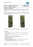
The Evaluation Board for the nRF24Z1 Single Chip 2.4 GHz RF audio streamer has been
developed to enable customers to test functionality, run communication and verify the
performance parameters of the device. This document describes the usage of the nRF24Z1EVBOARD.
The nRF24Z1-EVBOARD is intended for evaluation and development purposes only. It is
not intended for incorporation into an end product.
3.
Getting started
The nRF24Z1-EVBOARD V1-0 is shipped with an EEPROM programmer and emulator
(programming dongle). The nRF programming dongle enables you to download register
settings and access the control link offered by nRF24Z1.
The following equipment is needed to work efficiently with the nRF24Z1-EVBOARD:
•
•
•
•
•
PC with 1 free USB port
Z1config PC software (supplied)
1 nRF EEPROM programmer and emulator (supplied)
Two 2.0 V - 3.6V or one 4.6 – 12V DC voltage supply
1 male A/B USB cable (supplied)
To evaluate the performance of the device the following instrumentation should be available:
•
•
•
•
Audio source, analog or digital. Analog audio input is AC coupled, with a maximum
swing of 2.6Vpp (0.9Vrms). Minimum input resistance is 10kΩ. Digital audio input is via
S/PDIF RCA phono connector (0.5Vpp,75Ω)
Audio amplifier and loudspeakers. Analog audio out is 2.1Vpp (0.75Vrms) at a load of
5kΩ. Digital audio output is via S/PDIF RCA phono connector (0.5Vpp,75Ω)
Oscilloscope
2.4 GHz Spectrum analyzer
Nordic Semiconductor ASA
Revision: 1.3
-
Vestre Rosten 81, N-7075 Tiller, Norway
Page 2 of 27
-
Phone +47 72 89 89 00
-
Fax +47 72 89 89 89
May 2005