1
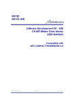
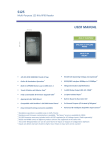
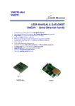
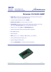
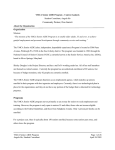
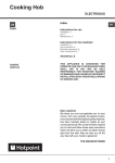
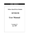
SM132-USB 13.56 MHz RFID Mifare® Read / Write USB Module DATA SHEET Complete Read/Write module including antenna Supports ISO14443A Mifare® Classic 1K , Mifare® Classic 4K , Mifare® Ultralight USB Interface USB Powered - No External Power required Fast data transfer - Contactless communication up to 106 KHz Secure - Encrypted contactless communication Upgradeable Ideal for e-money , secure access and fast data collection applications SonMicro Electronics Revision A.7 May, 2007 2 SM132USB – Datasheet 1. 1.1 INTRODUCTION 4 EVALUATION KIT – SM1320 USB 4 2. MIFARE® BRIEF TECHNICAL INFORMATION 6 3. COMMUNICATION PROTOCOLS 7 3.1 4. UART 8 COMMANDS & RESPONSES 9 4.1 RESET 9 4.2 READ FIRMWARE VERSION 9 4.3 SELECT TAG 10 4.4 SEEK FOR TAG 11 4.5 AUTHENTICATE 12 4.6 READ BLOCK 13 4.7 READ VALUE BLOCK 14 4.8 WRITE BLOCK 15 4.9 WRITE VALUE BLOCK 16 4.10 WRITE 4 BYTE BLOCK 17 4.11 WRITE MASTER KEY 18 4.12 INCREMENT VALUE BLOCK 19 4.13 DECREMENT VALUE BLOCK 20 4.14 SET ANTENNA POWER 21 4.15 READ INPUT PORT 22 4.16 WRITE TO OUTPUT PORT 23 4.17 HALT TAG 24 4.18 SET BAUD RATE 25 4.19 SLEEP 26 5. ELECTRICAL & PERFORMANCE SPECIFICATIONS 27 5.1 DC CHARACTERISTICS SonMicro Electronics 27 Revision A.7 May, 2007 3 SM132USB – Datasheet 5.2 OPERATING TEMPERATURE 27 5.3 ABSOLUTE MAXIMUM RATINGS 27 5.4 PERFORMANCE SPECIFICATIONS 27 6. SALES AND SERVICE INFORMATION SonMicro Electronics Revision A.7 28 May, 2007 4 SM132USB – Datasheet 1. INTRODUCTION SM132-USB is a compact 13.56MHz RFID Read / Write USB module integrated with PCB antenna and designed for ISO14443A standard and supports Mifare® Classic 1K, Mifare® Classic 4K and Mifare® Ultralight transponders. SM132-USB comes with the same firmware of SM130 Serial/I2C Mifare modules. USB to Serial protocol conversion is done by the module’s hardware thus user can access the module thru USB bus with the serial protocol. The serial protocol is explained in this document. SonMicro also released Software Development Kit, SDK, including ActiveX Control for users who do not want to deal with the protocol used. With the provided ActiveX Library, user can create PC based Mifare applications very quickly and there is no hardware or electronics knowledge is required. ActiveX Library comes free and with unlimited user license with –Deluxe- versions of the Development/Evaluation Kits. For details about SDK, please refer to SDK User Manual document found at http://www.sonmicro.com Mifare® Classic is a secure memory (1Kbyte, 4KByte) chip/card often called contactless smart card. The reason it is called smartcard is because it has increment and decrement functions designed for especially payment systems. Mifare® Classic family of tags is being used in RFID applications where very high security and fast data collection systems are required. This family of tags has contactless communication speed up to 106 KHz and uses very strong encryption techniques. It is impossible to copy or modify the content of the Mifare® Classic family of tags without the correct key(s) when it is protected. As a result Mifare® become ideal for e-money applications, secure access, data storage and fast data collection systems. Not only limited with these applications but printed antenna technology makes possible to find very thin and low cost Mifare® tags (e.g. labels, stickers) so that extending the field of RFID applications. Mifare® Ultralight differs from Mifare® Classic family. It has 512 bits memory and the contactless communication is not encrypted. However it has anti-cloning support by unique 7 byte serial number of each device. 1.1 EVALUATION KIT – SM1320 USB SM1320 is a professional evaluation kit for SM132-USB modules. SM1320 evaluation kit can be used to develop your application quickly or it can simply demonstrate main features of the SM132-USB module. SM1320 can be also used as stand alone Mifare® Programmer / Reader. Designers can develop or evaluate their own specific application with the kit. It is ideal for any Mifare application such as Customer Loyalty, e-purse applications that needs to be connected to the PC with USB. SM1320 Evaluation Kit comes with original SMRFID Mifare® Software, USB Driver and SDK tools SMRFID Mifare® Software makes easy to start with SM1320 evaluation kit. Software provides Mifare® Programmer / Writer , Mifare Reader® features as well as setting configuration parameters of SM132USB modules. SDK includes ActiveX Component, example Visual Basic project and SDK user Manual document. For a very quick and painless start we recommend you to buy a low cost SM1013 Evaluation kit. SonMicro Electronics Revision A.7 May, 2007 5 SM132USB – Datasheet For latest Documentation & Software: http://www.sonmicro.com/1356/d1356.php For Online Store: http://www.sonmicro.com/shop/shop3.php SonMicro Electronics Revision A.7 May, 2007 6 SM132USB – Datasheet 2. MIFARE® BRIEF TECHNICAL INFORMATION For Mifare® tag memory organization and communication principles please refer to SM130 User Manual document. For deeper details refer to m001051.pdf document (Standard Card IC MF1 IC S50) of Philips Semiconductor. Mentioned document gives functional specification of the IC used in Mifare® 1K tags. Same communication principles are valid for Mifare® 4K (MF1 IC S70) tags. Documents can be downloaded at http://www.sonmicro.com/1356/d1356.php Communication principles are greatly simplified by SM130 module as follows: POR Select is required again if tag had left the RF field or halted SELECT Authentication required if sector or access condition is changing AUTHENTICATE No need to authenticate again if sector is not changing provided that the block(s) has same access conditions with previous operations MEMORY OPERATIONS Read Write Increment Value Decrement Value Figure 1 – Flow diagram to perform operations on Mifare® tag The following sequence of operations has to be performed to access any block in the tag. 1 – The tag should be selected with the serial number. 2 – The relevant Sector should be authenticated with the relevant key. For example, if a block has to be read and if the access condition of the block is KeyB, then the sector should be authenticated using KeyB 3 – After the authentication, the required operation may be performed on the block of the authenticated sector. The operation will be allowed only if the access conditions for the block allow this. For example, if a block has Read condition using KeyB and write condition using KeyA/B then authenticating using KeyA will only allow a write operation. If a read is attempted the tag will halt and will not grant any further access. For accessing the tag further, it has to be again selected and authenticated. Also, only the sector that has been authenticated may be accessed. For example, if Sector 1 has been authenticated to access Block6 and if Block 9 is accessed, the tag will halt. SonMicro Electronics Revision A.7 May, 2007 7 SM132USB – Datasheet 3. COMMUNICATION PROTOCOLS SM132-USB is connected to the PC thru USB but the protocol implemented by UART/Serial. The USB to Serial conversion will be done by the module hardware The following table lists the commands supported by SM132-USB module and the corresponding code. Note that for users who are using ActiveX library can skip this section and investigate SDK User Manual document for the software commands. Code Command Description 0x80 Reset Resets the Module 0x81 Firmware Reads the Firmware Revision of the Module 0x82 Seek for Tag Continuously checks for presence of a tag 0x83 Select Tag Selects a Tag 0x84 NA Not Implemented 0x85 Authenticate Authenticates the selected Block 0x86 Read Block Reads from the specified Block 0x87 Read Value Reads from a Value Block 0x88 NA Not Implemented 0x89 Write Block Writes the data to the specified block 0x8A Write Value Formats and Writes a Value block 0x8B Write 4 Byte Block Writes 4 byte data to Mifare Ultralight block 0x8C Write Key Writes the Key to the EEPROM of the MFRC530 0x8D Increment Increments a value block 0x8E Decrement Decrements a value block 0x8F NA Not Implemented 0x90 Antenna Power Switches ON or OFF the RF field 0x91 Read port Reads from the Input port 0x92 Write Port Writes to the Output port 0x93 Halt Halts the PICC 0x94 Set Baud Rate Sets the new baud rate 0x95 NA Not Implemented 0x96 Sleep This command puts SM130 in sleep mode Table 1– Serial Commands to control SM132-USB module. SonMicro Electronics Revision A.7 May, 2007 8 SM132USB – Datasheet 3.1 UART The communication between the host and the module can take place at 9600bps, 19200bps, 38400bps, 57600bps or 115200bps N, 8, 1. Module communicates at 19200bps,N,8,1 as default. Once the baud rate is changed using the Change baud rate command, successful communication will only occur with the new baud rate. The host first sends the command and the module executes the operation and replies with a response to the command. The host can analyze the reply to check if the operation was successful or if any error occurred during the operation. Following is the UART frame for the commands sent by the host: Header Reserved Length Command Data CSUM 1 Byte 1 Byte 1 Byte 1 Byte N Bytes 1 Byte Table 2 – UART frame send by Host 1. Header: This is a single byte that indicates the beginning of a frame. This byte should be always 0xFF 2. Reserved: This byte is reserved for future use and not implemented currently. It has to be always 0x00 3. Length: This byte is used to indicate the length of the payload data. This includes the Command and the Data bytes 4. Command: This byte is used to instruct the module on what operation to perform 5. Data: These are parameters necessary for the module to execute the command. For example, for a Read command, the data will be the block number to be read. For a Write command, this will be the block number and 16 bytes of data. 6. CSUM: This is the checksum byte. This byte is used on the host as well as the module to check the validity of the packet and to trap any data corruption. This is calculated by adding all the bytes in the packet except the Header byte Following is the UART frame for the response packets sent by SM130 module in response to the commands: Header Reserved Length Command Response CSUM 1 Byte 1 Byte 1 Byte 1 Byte N Bytes 1 Byte Table 3 – UART frame send by SM130 module 1. Header: This is a single byte that indicates the beginning of a frame. This byte will be always 0xFF 2. Reserved: This byte is reserved for future use and not implemented currently. It is 0x00 3. Length: This byte is used to indicate the length of the payload data. 4. Command: This is the command for which the response is being sent back. The host can use this byte to verify that the received response is for the command it sent. 5. Response: This contains the result data if an operation was successful or the error code if the operation was not successful. The status of the operation can be found by the length of the data bytes. For example, if the data length is 16 when a read command is executed it means that the operation was successful. If the data length is 1, then it means that the read was not successful and the nature of the error can be found out by analyzing the Error code sent, which is the single data byte 6. CSUM: This is the checksum byte. This is the sum of al bytes except the Header byte SonMicro Electronics Revision A.7 May, 2007 9 SM132USB – Datasheet 4. COMMANDS & RESPONSES In this chapter detailed information and UART frame examples are given for command and responses. 4.1 RESET This command generates software reset on the module. Command: Command Data 0x80 None Table 4 – Reset Command Response: The module responds with a version string to the reset command. The response is the same as the one found in the Read Firmware Version Command Example Command: FF 00 01 80 81 Reset SM132-USB module Example Response: FF 00 04 81 30 2E 31 14 – Version is 0.1 4.2 READ FIRMWARE VERSION This command reads the firmware version of the module Command: Command Data 0x81 None Table 5 – Read Firmware Version Command Response: The module responds with a version string to this command. Example Command: FF 00 01 81 82 Example Response: FF 00 04 81 30 2E 31 14 – Version is 0.1 SonMicro Electronics Revision A.7 May, 2007 10 SM132USB – Datasheet 4.3 SELECT TAG This command Selects a Tag if it is present in the field. On receiving the command, the module executes an Anti-collision and Select command sequences. If a tag was present, then it selects the tag and sends the serial number of the tag as response. If a tag was not present, it sends an error code back. Command: Command Data 0x83 None Table 6 – Select Command Response: If a tag was selected, the response data length is 6 or 9 bytes. The first byte is the command byte (0x83) and the next is the Tag Type and the next 4 bytes / 7 bytes are the tag serial number MSB first. The serial number is 4 bytes for Mifare 1K and 4K tags and 7 bytes for Mifare Ultralight tags. Data Length Command/Response Tag Type Serial Number 0x06 or 0x09 0x83 1 Byte 0x01 – Mifare Ultralight 0x02 – Mifare Standard 1K 0x03 – Mifare Classic 4K 0xFF – Unknown Tag type 4 Byte / 7 Byte Serial Number, 1st byte is the MSB Table 7 – Response to Select Command If no tag was present, the data length is set to 1 and the Error code returned is ‘N’ If RF Field is OFF, the data length is set to 1 and the Error code returned is ‘U’ Data Length 0x02 Command/Response 0x83 Error Code 0x4E 0x55 ‘N’ - No Tag present. ‘U’ – Access failed due to RF Field is OFF Table 8 – Response to Select Command Example Command: FF 00 01 83 84 Select Tag Example Response: FF 00 06 83 01 39 0D 4C D2 EE Mifare® 1K tag selected, Serial Number 390D4CD2 FF 00 02 83 4E D3 No Tag present SonMicro Electronics Revision A.7 May, 2007 11 SM132USB – Datasheet 4.4 SEEK FOR TAG This command seeks and selects a Tag as soon as the tag presents in the field. On receiving the command, the module executes an Anti-collision and Select command sequences. As soon as the tag enters into the RF field, then module selects the tag and sends the serial number of the tag as response. Command: Command Data 0x82 None Table 9 – Seek For Tag Command Response: When this command is executed and immediate response arrives as in Table 16 to show that Seek For Tag command is in progress or failed. Data Length 0x02 Command/Response 0x82 Error Code 0x4C 0x55 ‘L’ – Command in progress. ‘U’ – Command in progress but RF Field is OFF Table 10 – Response to Seek For Tag Command As soon as a tag enters into the RF field it is selected and the response data length is 6 or 9 bytes according to tag type. The first byte is the command byte (0x82) the second is the Tag Type and the next 4 bytes / 7 bytes are the tag serial number MSB first. The serial number is 4 bytes for Mifare 1K and 4K tags and 7 bytes for Mifare Ultralight tags. Data Length Command/Response Tag Type Serial Number 0x06 or 0x09 0x82 1 Byte 0x01 – Mifare Ultralight 0x02 – Mifare Standard 1K 0x03 – Mifare Classic 4K 0xFF – Unknown Tag type 4 Byte / 7 Byte Serial Number, 1st byte is the MSB Table 11 – Response to Seek For Tag Command Example Command: FF 00 01 82 83 Seek for Tag Example Response: Response 1: FF 00 02 82 4C D0 Command is being executed. (Module waits here for a tag to enter into the RF Field) Response 2: FF 00 06 82 02 D4 5A 8D 55 9A Mifare® 1K tag selected, Serial Number 558D5AD4 SonMicro Electronics Revision A.7 May, 2007 12 SM132USB – Datasheet 4.5 AUTHENTICATE This command authenticates the specified block with the specified Key type and Key sequence. Command: Command Block Number 0x85 1 Byte – Block number to be authenticated 1 Byte – Option byte that instructs the module which type of key to be used for authentication Key Type 0xAA: Authenticate with Key type A 0xBB: Authenticate with Key type B 0xFF: Authenticate with Key type A and transport key FF FF FF FF FF FF 0x10 to 0x1F: Authenticate with Key type A using the key stored in the SM130 module’s E2PROM (0 to 15) 0x20 to 0x2F: Authenticate with Key type B using the key stored in the SM130 module’s E2PROM (0 to 15) Key 6 Bytes – Key to be used for authentication. Table 12 – Authenticate Command Response: Data Length Command/Response 0x06 0x85 1 Byte – Status / Error code Status / Error Code 0x4C 0x4E 0x55 0x45 ‘L’ – Login Successful ‘N’ – No Tag present or Login Failed ‘U’ – Login Failed ‘E’ – Invalid key format in E2PROM Table 13 – Response to Authenticate Command Example Command: FF 00 03 85 01 FF 88 Authenticate Block 0x01 with transport key FF FF FF FF FF FF FF 00 09 85 05 AA 11 23 43 FC 97 CD 14 Authenticate Block 0x05 with key type A, and Key 11 23 43 FC 97 CD FF 00 03 85 02 11 9B Authenticate Block 0x02 with Key type A from the SM132-USB’s internal EEPROM sector number 0x01 FF 00 03 85 02 23 AD Authenticate Block 0x02 with key type B from the SM132-USB’s internal EEPROM sector number 0x03 Example Response: FF 00 02 85 4C D3 Login Successful FF 00 02 85 4E D5 No Tag present or Login Failed SonMicro Electronics Revision A.7 May, 2007 13 SM132USB – Datasheet 4.6 READ BLOCK This command reads 16 bytes from the specified block. Before executing this command, the particular block should be authenticated. If not authenticated, this command will fail. Command: Command Block Number 0x86 1 Byte – Block Number to be read Table 14 – Read Block Command Response: Success: Data Length 0x12 Command/Response 0x86 Block Number Data 1 Byte – Block number that has been read 16 Bytes – 16 bytes of data that have been read from the specified block Table 15 – Response to Read Block Command Fail: Data Length 0x02 Command/Response 0x86 1 Byte – Error Code Error Code 0x4E 0x46 ‘N’ – No Tag present ‘F’ – Read Failed Table 16 – Response to Read Block Command Example Command: FF 00 02 86 06 8E Read 16 bytes from Block 0x06 Example Responses: FF 00 12 86 06 00 01 02 03 04 05 06 07 08 09 0A 0B 0C 0D 0E 0F 16 Read successful FF 00 02 86 46 CE Read Failed Note: When reading a Mifare UL tag, the first 4 bytes are from the block number specified. The next 12 bytes are from the consecutive blocks. SonMicro Electronics Revision A.7 May, 2007 14 SM132USB – Datasheet 4.7 READ VALUE BLOCK This command reads a value block. Value is a 4byte signed integer. Before executing this command, the block should be authenticated. If the block is not authenticated, this command will fail. Also, this command will fail if the block is not in valid Value format. Command: Command 0x87 Block Number 1 Byte – Block Number to be read Table 17 – Read Value Block Command Response: Success: Data Length 0x06 Command/Response 0x87 Block Number Data 1 Byte – Value Block number that has been read 4 Bytes – Value read from the value block. LSB first Table 18 – Response to Read Value Block Command Fail: Data Length 0x02 Command/Response 0x87 1 Byte – Error Code Error Code 0x4E 0x49 0x46 ‘N’ – No Tag present ‘I’ – Invalid Value Block ‘F’ – Read Failed Table 19 – Response to Read Value Block Command Example Command: FF 00 02 87 08 91 Read Value from Block 0x08 Example Responses: FF 00 06 87 08 10 27 00 00 CC Read Value is successful. The value read is 10000. (0x00002710) FF 00 02 87 46 CF Read Failed FF 00 02 87 49 D2 Invalid Value Block SonMicro Electronics Revision A.7 May, 2007 15 SM132USB – Datasheet 4.8 WRITE BLOCK This command writes 16 bytes to the specified block. Before executing this command, the particular block should be authenticated. If not authenticated, this command will fail. Command: Command Block Number Data 0x89 1 Byte – Block Number to be written 16 Bytes – 16 bytes of data to be written to the block. Table 20 – Write Block Command Response: Success: Data Length 0x12 Command/Response 0x89 Block Number Data 1 Byte – Value Block number that has been written 16 Bytes – 16 bytes of data that have been read back after the write Table 21 – Response to Write Block Command Fail: Data Length 0x01 Command/Response 0x89 1 Byte – Error Code Error Code 0x55 0x58 0x4E 0x46 ‘U’ – Read after write failed (*) ‘X’ – Unable to Read after write (*) ‘N’ – No Tag present ‘F’ – Write Failed Table 22 – Response to Write Block Command (*)After a block is written, it is read back and verified if the write was successful. If the data read back does not match the data written, the error will be “U”. For example, while writing to sector trailer to update Key-A, the value read back will not match the value written.(Key A reads always 00 00 00 00 00 00) If the block that was written is read protected, then read will fail and the error code will be “X”. If the write is successful and the data is successfully verified, then the same data that was written is sent back in the response packet. Example Command: FF 00 12 89 0A 00 01 02 03 04 05 06 07 08 09 0A 0B 0C 0D 0E 0F 1D Write 16 bytes data ( 00 01 02 03 04 05 06 07 08 09 0A 0B 0C 0D 0E 0F) to block 10 Example Responses: FF 00 12 89 0A 00 01 02 03 04 05 06 07 08 09 0A 0B 0C 0D 0E 0F 1D Write successful FF 00 02 89 58 E3 Unable to read after write. FF 00 02 89 55 E0 Read after write failed SonMicro Electronics Revision A.7 May, 2007 16 SM132USB – Datasheet 4.9 WRITE VALUE BLOCK This command formats and then writes a value block. Value is a 4 byte signed integer. Only the 4-byte value and block number need to be sent to the module. The module formats the value block and then writes. After writing, the Value block is read back to verify if the write was successful. Before executing this command, the block should be authenticated. If the block is not authenticated, this command will fail. Command: Command 0x8A Block Number 1 Byte – Block Number to be written Data 4 Bytes – 4 byte long int value. LSB first Table 23 – Write Value Block Command Response: Success: Data Length 0x06 Command/Response 0x8A Block Number Data 1 Byte – Block number to which value has been written 4 Bytes – Value that has been read back after the write.(LSB first) Table 24 – Response to Write Value Block Command Fail: Data Length 0x02 Command/Response 0x8A 1 Byte – Error Code Error Code 0x4E 0x49 0x46 ‘N’ – No Tag present ‘I’ – Invalid Value Block. The block was not in the proper value format when read back. This could be because there was an error in writing ‘F’ – Read Failed during verification Table 25 – Response to Write Value Block Command Example Command: FF 00 06 8A 08 10 27 00 00 CF Write value 10000(0x00002710) to block 8 Example Responses: FF 00 06 8A 08 10 27 00 00 CF Write Value successful FF 00 02 8A 4E DA No Tag present SonMicro Electronics Revision A.7 May, 2007 17 SM132USB – Datasheet 4.10 WRITE 4 BYTE BLOCK This command writes 4 bytes to the specified Mifare block. This command has been provided to write to Mifare Ultralight tags. Command: Command Block Number Data 0x8B 1 Byte – Block Number to be written 4 Bytes – 4 bytes of data to be written to the block. Table 26 – Write 4 Byte Block Command Response: Success: Data Length 0x06 Command/Response 0x8B Block Number Data 1 Byte – Value Block number that has been written 4 Bytes – 4 bytes of data that have been read back after the write Table 27 – Response to Write 4 Byte Block Command Fail: Data Length 0x01 Command/Response 0x8B 1 Byte – Error Code Error Code 0x55 0x58 0x4E 0x46 ‘U’ – Read after write failed (*) ‘X’ – Unable to Read after write (*) ‘N’ – No Tag present ‘F’ – Write Failed Table 28 – Response to Write 4 Byte Block Command After a block is written, it is read back and verified if the write was successful. If the data read back does not match the data written, the error will be “U”. If the write is successful and the data is successfully verified, then the same data that was written is sent back in the response packet. Example Command: FF 00 06 8B 04 AA BB CC DD A3 Write 4 bytes data (AA BB CC DD) to page 4 Example Responses: FF 00 06 8B 04 AA BB CC DD A3 Write successful FF 00 02 8B 46 D3 Write failed SonMicro Electronics Revision A.7 May, 2007 18 SM132USB – Datasheet 4.11 WRITE MASTER KEY This command writes the Key to the internal EEPROM of the module. There are 16 key sectors in the module. Each sector can hold a TypeA and a TypeB key. The sectors are numbered from 0 to 15. The keys cannot be read back after a write. To check if the key write was successful, execute an authenticate command using the key from EEPROM. Command: Command Internal EEPROM Sector Number Key Type Key 0x8C 1 Byte – Key sector number where the keys has to be stored. This can be 0x00 to 0x0F ( Total of 16 sectors ) 1 Byte – Key Type to e stored I the specified sector 0xAA – Key is stored as TypeA 0xBB – Key is stored as TypeB 6 Bytes – Six byte Key ( MSB first ) Table 29 – Write Master Key Command Response: The following single byte response is received from the module: Data Length Command/Response 0x02 0x8C 1 Byte – Status / Error Code Status / Error Code 0x4C 0x4E ‘L’ – Write Master key successful ‘N’ – Write Master key fail Table 30 – Response to Write Master Key Command Example Command: FF 00 09 8C 06 AA 01 02 03 04 05 06 5A Write key (01 02 03 04 05 06) as TypeA to sector 6 of the internal eeprom of the module. FF 00 09 8C 06 BB 01 02 03 04 05 06 6B Write key (01 02 03 04 05 06) as TypeB to sector 6 of the internal eeprom of the module. Example Responses: FF 00 02 8C 4C DA Write Key successful FF 00 02 8C 4E DA Write Key failed SonMicro Electronics Revision A.7 May, 2007 19 SM132USB – Datasheet 4.12 INCREMENT VALUE BLOCK This command increments a value block with the specified amount. Before executing this command, the block should be authenticated. Also, the block should have permission for increment. If either of these conditions is not true, this command will fail. The 4-byte increment value should be sent LSB first. If the increment was successful, the 4-byte value after increment is sent back as response, LSB first. Command: Command Block Number Increment Value 0x8D 1 Byte – Block number to be incremented 4 Bytes – Increment value. ( LSB first ) Table 31 – Increment Value Block Command Response: Success: Data Length 0x06 Command/Response 0x8D Block Number Data 1 Byte – Block number that has been incremented 4 Bytes – Value after the increment. ( LSB first ) Table 32 – Response to Increment Value Block Command Fail: Data Length 0x01 Command/Response 0x8D 1 Byte – Error Code Error Code 0x4E 0x46 ‘N’ – No Tag present ‘F’ – Read Failed during verification Table 33 – Response to Increment Value Block Command Example Command: FF 00 06 8D 08 E8 03 00 00 86 Increment Value Block 8 by 1000 (0x000003E8) Example Responses: FF 00 06 8D 08 F8 2A 00 00 BD Increment value block successful. New Value is 11000 (0x00002AF8) FF 00 02 8D 46 D5 Increment failure SonMicro Electronics Revision A.7 May, 2007 20 SM132USB – Datasheet 4.13 DECREMENT VALUE BLOCK This command decrements a value block with the specified amount. Before executing this command, the block should be authenticated. Also, the block should have permission for decrement. If either of these conditions is not true, this command will fail. The 4-byte increment value should be sent LSB first. If the decrement was successful, the 4-byte value after decrement is sent back as response, LSB first. Command: Command Block Number Decrement Value 0x8E 1 Byte – Block number to be decremented 4 Bytes – Decrement value. ( LSB first ) Table 34 – Decrement Value Block Command Response: Success: Data Length 0x06 Command/Response 0x8E Block Number Data 1 Byte – Block number that has been decremented 4 Bytes – Value after the decrement. ( LSB first ) Table 35 – Response to Decrement Value Block Command Fail: Data Length 0x01 Command/Response 0x8E 1 Byte – Error Code Error Code 0x4E 0x46 ‘N’ – No Tag present ‘F’ – Read Failed during verification Table 36 – Response to Decrement Value Block Command Example Command: FF 00 06 8E 08 E8 03 00 00 87 Decrement Value Block 8 by 1000 (0x000003E8) Example Responses: FF 00 06 8E 08 28 23 00 00 E7 Decrement value block successful. New Value is 9000 (0x00002328) FF 00 02 8E 46 47 Decrement failure SonMicro Electronics Revision A.7 May, 2007 21 SM132USB – Datasheet 4.14 SET ANTENNA POWER This command turns ON or OFF the RF field. RF field can be switched off when it is not required. This helps to reduce the active current consumption. The RF field can be switched ON whenever a read or write operation is required. Command: Command RF SWITCH 0x90 1 Byte – Byte to instruct the reader whether to switch ON or OFF the RF field 0x00 – Switch Off RF Field Non-Zero – Switch On RF Field Table 37 – Set Antenna Power Command Response: Data Length 0x02 Command/Response 0x90 1 Byte – RF field status after execution of the command Status 0x00 0x01 RF Field switched Off RF Field switched On Table 38 – Response to Set Antenna Power Command Example Command: FF 00 02 90 00 92 Switch Off RF field FF 00 02 90 01 93 Switch On RF field Example Responses: FF 00 02 90 00 92 RF field Switched Off FF 00 02 90 01 93 RF field Switched On SonMicro Electronics Revision A.7 May, 2007 22 SM132USB – Datasheet 4.15 READ INPUT PORT This command can not be used with SM132-USB Modules because there is no input pin connection in hardware. Command: Command 0x91 Table 39 – Read Input Port Command Response: Data Length 0x02 Command/Response 0x91 1 Byte – Status of input pins Bit0 – Status of INPUT1. 1 – On, 0 – Off Bit1 – Status of INPUT2. 1 – On, 0 – Off Status Bit1 0 0 1 1 Bit0 0 1 0 1 INPUT2 LOW, INPUT1 LOW INPUT2 LOW, INPUT1 HIGH INPUT2 HIGH, INPUT1 LOW INPUT2 HIGH, INPUT1 HIGH Table 40 – Response to Read Input Port Example Command: FF 00 01 91 92 Read Input pins Example Responses: FF 00 02 91 00 93 INPUT2 LOW, INPUT1 LOW FF 00 02 91 01 94 INPUT2 LOW, INPUT1 HIGH FF 00 02 91 02 95 INPUT2 HIGH, INPUT1 LOW FF 00 02 91 03 96 INPUT2 HIGH, INPUT1 HIGH SonMicro Electronics Revision A.7 May, 2007 23 SM132USB – Datasheet 4.16 WRITE TO OUTPUT PORT This command can not be used with SM132-USB Modules because there is no output pin connection in hardware. Command: Command 0x92 1 Byte – Byte that indicates how the outputs have to be set Bit0 – OUTPUT1. 1 – On, 0 – Off Bit1 – OUTPUT2. 1 – On, 0 – Off Status Bit1 0 0 1 1 Bit0 0 1 0 1 OUTPUT2 LOW, OUTPUT1 LOW OUTPUT2 LOW, OUTPUT1 HIGH OUTPUT2 HIGH, OUTPUT1 LOW OUTPUT2 HIGH, OUTPUT1 HIGH Table 41 – Write to Output Port Command Response: Data Length 0x02 Command/Response 0x92 1 Byte – Status of output pins after the command execution Status Bit0 – Status of OUTPUT1. 1 – On, 0 – Off Bit1 – Status of OUTPUT2. 1 – On, 0 – Off Table 42 – Response to Write to Output Port Command Example Command: FF 00 02 92 00 94 Switch Off both outputs FF 00 02 92 01 95 Switch On Output1 FF 00 02 92 03 97 Switch On both outputs Example Responses: FF 00 02 92 00 94 Both outputs switched Off FF 00 02 92 01 95 OUTPUT1 switched On FF 00 02 92 03 97 Both outputs switched On SonMicro Electronics Revision A.7 May, 2007 24 SM132USB – Datasheet 4.17 HALT TAG This command executes a Mifare Halt command on the selected tag. Command: Command Data 0x93 None Table 43 – Select Command Response: Data Length 0x02 Command/Response 0x93 Error Code 0x4C 0x55 ‘L’ – PICC(tag) is halted ‘U’ – PICC can not be halted due to RF Field is OFF Table 44 – Response to Select Command Example Command: FF 00 01 93 94 Halt Tag Example Response: FF 00 02 93 55 EA PICC halted SonMicro Electronics Revision A.7 May, 2007 25 SM132USB – Datasheet 4.18 SET BAUD RATE This command sets the UART baud rate of the module. Once it is set module will be able to communicate with new baud rate even after POR. SM132-USB module operates at a default baud rate of 19200bps when shipped from the factory. As soon as this command is received, the module stores the new baud rate in its internal EEPROM and after a delay of 500ms transmit the response using the new baud rate. Command: Command 0x94 1 Byte – Determines the new baud rate Baud Rate 0x00 – 9600bps 0x01 – 19200bps 0x02 – 38400bps 0x03 – 57600bps 0x04 – 115200bps Table 45 – Set Baud Rate Command Response: Data Length 0x02 Command/Response 0x94 1 Byte – Status / Error Code Status/Error Code 0x4C 0x4E ‘L’ – Change of Baud rate successful ‘N’ – Change of Baud rate failed Table 46 – Response to Set Baud Rate Command Example Command: FF 00 02 94 02 98 Set new baud rate to 38400bps FF 00 02 94 03 99 Set new baud rate to 57600bps Example Responses: FF 00 02 94 4C E2 Baud rate changed successfully FF 00 02 94 4E E4 Baud rate change operation failed SonMicro Electronics Revision A.7 May, 2007 26 SM132USB – Datasheet 4.19 SLEEP This command should not be used with SM132-USB modules otherwise SM132-USB module should be reset-ed by hand to operate it again. This command puts SM132-USB in sleep mode to reduce power consumption. The module switches off the RF field and enters a low power sleep mode. Only a hardware reset can bring the module out of the sleep state. Command: Command Data 0x96 None Table 47 – Sleep Command Response: Data Length 0x02 Command/Response 0x96 Error Code 0x00 Table 48 – Response to Sleep Command Example Command: FF 00 01 96 97 Sleep Commnad Example Responses: FF 00 02 96 00 98 Sleep OK SonMicro Electronics Revision A.7 May, 2007 27 SM132USB – Datasheet 5. ELECTRICAL & PERFORMANCE SPECIFICATIONS 5.1 DC CHARACTERISTICS Symbol VCC RFVCC Description Min Typ Ma x Units Supply Voltage 4.75 5.00 5.5 V RF Supply Voltage 4.5 5 5.5 V Notes Io Supply Current - 180mA - Continuous Read Mode Is Sleep Current - 30uA - Sleep Mode Table 49 – DC Chacteristics 5.2 OPERATING TEMPERATURE Symbol Min Typ Max Units TA Ambient Temperature Description -40 - 85 °C TJ Junction Temperature -40 - 100 °C Notes Table 50 – Operating Temperature 5.3 ABSOLUTE MAXIMUM RATINGS Symbol Min Typ Max Units TSTG Storage Temperature Description -55 - 100 °C TA Ambient Temperature -40 - 85 °C VCC Supply Voltage -0.5 - 5.5 V IMIO Maximum Current into any Port Pin -25 - 50 mA ESD Electro Ststic Discharge Voltage 2000 - - V Notes Higher storage temperatures will reduce data retention time Human Body Model ESD Table 51 – Absolute Maximum Ratings 5.4 PERFORMANCE SPECIFICATIONS Parameter Min Typ Max Units Read Distance - 5 7 cm Write Distance - 5 7 cm Notes Table 52 – Performance Specifications SonMicro Electronics Revision A.7 May, 2007 28 SM132USB – Datasheet 6. SALES AND SERVICE INFORMATION To obtain information about SONMicro Electronics products and technical support, reference the following information. SONMicro ELECTRONICS LTD. Cankaya M. Soguksu C. Aslihan Ishani 2/15 Mersin, 33070 TURKIYE Phone: Facsimile: Email: Web Site: +90 324 237 21 28 +90 324 237 21 86 [email protected] http://www.sonmicro.com Sales Support Documents & Software User Forums SonMicro Electronics http://www.sonmicro.com/sales.php http://www.sonmicro.com/ask.php http://www.sonmicro.com/1356/d1356.php http://www.sonmicro.com/forums/ Revision A.7 May, 2007