1
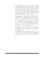
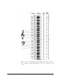
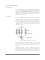
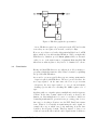
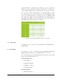
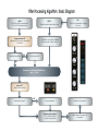
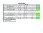
QUANTUM MASTERING LPEQ
L INEAR PHASE PARAMETRIC EQUALIZER
U SER M ANUAL
Quantum-music.ca ©
2013
Quantum Matering LPEQ User Manual
Quantum-Music.ca
Version 1.0
2013
Thank you for downloading Quantum Matering LPEQ. Keep in mind that this is
a free plugin, it doesn’t come with any support or warranty. Please read this guide
carefully before using the software so you can enjoy the full Quantum experience!
Contents
1 About Quantum LPEQ
3
1.1
Features . . . . . . . . . . . . . . . . . . . . . . . . . . . . . . . . .
3
1.2
Linear phase
4
. . . . . . . . . . . . . . . . . . . . . . . . . . . . . .
2 Using Quantum Matering LPEQ
5
2.1
Interface overview . . . . . . . . . . . . . . . . . . . . . . . . . . .
5
2.2
General functions . . . . . . . . . . . . . . . . . . . . . . . . . . . .
7
2.3
Band functions . . . . . . . . . . . . . . . . . . . . . . . . . . . . .
8
3 Digital Signal Processing
12
3.1
Filter types . . . . . . . . . . . . . . . . . . . . . . . . . . . . . . .
12
3.2
Filtering . . . . . . . . . . . . . . . . . . . . . . . . . . . . . . . . .
12
3.3
Convolution . . . . . . . . . . . . . . . . . . . . . . . . . . . . . . .
13
3.4
Algorithm . . . . . . . . . . . . . . . . . . . . . . . . . . . . . . . .
14
4 Conclusion
14
1
About Quantum LPEQ
Quantum LPEQ was designed as part of 4th year undergraduate
project at Ecole Polytechnique de Montral in collaboration with Christopher Dion from Quantum-Music. Our challenge in designing the
Quantum Mastering LPEQ was to provide a parametric linear phase
EQ for VST 2.0 with transparent sound and intuitive interface. And
best of all, free of charge!
1.1
Features
Audio:
• Sample rates: 44.1 kHz, 48 kHz, 88.2 kHz, 96 kHz
• Resolution: 16, 24, 32 bits
• Range: 20Hz-20kHz
• Windows 32-bit support
• Left/Right or Mid/Side operation
• VU-meter
• Peak detection
• ± 6dB gain on 8 mono or 4 stereo channels
• Fixed 30Hz Low-Cut and 18kHz High-Cut
Interface:
• Solo buttons for individual channels
• Separate Gain knobs for individual channels and one input gain
control
• Peak metering with VU & peak indicator
• Enter values directly with the keyboard
Why choose Quantum LPEQ?
• True Linear phase processing
• Innovative Bandwidth & Precision controls
Quantum Matering LPEQ User Manual
3
• Cost!
• Ressources available at quantum-music.ca
With its parametric design, each band can be adjusted in terms of
frequency, bandwidth and Q factor to give as much control possible
to shape the sound spectrum.
1.2
Linear phase
For the untrained ear, a non-linear phase EQ, which is pretty much
the standard way to design EQs, doesn’t sound much di↵erent from a
linear phase one. However, for experienced studio engineers who crave
for sound purity and don’t want any coloration, or for hobbyists who
want the most precise equalization, linear-phase EQs provide a more
subtle control. Where minimum-phase or analog EQ’s add frequency
smearing to the sound, linear-phase EQ’s keep a constant “timing”
of all frequencies, which is great for making a frequency band louder
or quieter without changing other aspects of its relationship with the
music around it.
To put it into numbers, a first order filter minimum-phase EQ (meaning analog hardware or digital IIR filters with 6dB/octave slope)
adds/subtracts 90 degrees of phase shift over a two octaves region
around the center frequency for each 6dB of boost/cut. For steeper
slopes, the filter order goes up and so does the phase shift, up to a
point where it goes beyond 360 degrees and really becomes a delay,
but only on a portion of the frequency spectrum. And because the
brain is particularly sensitive to this, it actually uses the phase di↵erence in audio signals to create the 3D image of sound, messing with
phase means messing with the spacial perception of music. Now this
doesn’t mean this sounds bad, it may even be something you look for
in the mix, that’s what adding reverb does. It simply means that if
you already have a good mix, you may want to keep it as true to the
original as possible while performing some corrections.
When applying equalization using a well-designed EQ, the frequency
response should look similar in terms of magnitude, no matter if the
EQ has linear phase or not. As you can see on Figures 1 and 2 ,
both filters have the same cuto↵ frequency of 10.8kHz (blue line),
though with a slightly di↵erent response in the cuto↵ region. , which
is keeping the phase intact all across the audio spectrum. As you can
see on Figures 1 and 2 (green line), the phase response in the passband
region is linear for the FIR and nonlinear for the IIR. Whether this
is an advantage from an audio point of view, there have been lenghty
discussions about this, but from a purely mathematical point of view,
there’s no contest that linear phase EQs provide a “cleaner” signal.
Quantum Matering LPEQ User Manual
4
Figure 1: FIR filter magnitude and phase response (100 coefficients,
Hamming Window)
Figure 2: IIR filter magnitude and phase response (100 coefficients,
Butterworth)
2
Using Quantum Matering LPEQ
In this section, we are going to introduce the interface and the basic
and advanced functions available to the user. We will also explain
how to use Quantum Mastering EQ efficiently with an example of a
mastering workflow.
2.1
Interface overview
The first noticeable thing when opening Quantum Mastering EQ is
that the whole interface is divided into two “symmetrical” parts. For
each channel, the Gain knob enables you to trim the balance between
Left and Right channels, or Mid and Side if operating in MS Mode.
Quantum Matering LPEQ User Manual
5
The Solo button enables you to work exclusively on one channel at
a time (yellow LED turned on), a critical feature in MS mode. Be
careful! Do NOT leave this switch ON when bouncing or rendering
your tracks, it will be printed as-is!
The left part is used either for adjusting the Left channel when in
stereo mode, or for adjusting the Mid channel when in Mid/Side
mode (red LED turned on).
The right part is used either for adjusting the Right channel when
in stereo mode, or for adjusting the Side channel when in Mid/Side
mode.
Quantum Matering LPEQ User Manual
6
2.2
General functions
Here, we will describe the plugin controls that are not band-specific,
meaning they will a↵ect the overall behaviour of the plugin, on both
channels, without regards to the band settings.
The Bypass toggle switch gives the user the choice to bypass entirely
the plugin. It’s an easy way to hear the di↵erence between processed
and unprocessed audio.
The Low-cut provides the ability to cut o↵ undesirable frequencies
below 30Hz with a very agressive slope of -30dB/Octave. This proves
to be handy to clear out the mix of sub-frequencies that eat up unnecessary energy in the mix. It is active by default.
Figure 3: Fixed 30Hz Low-cut
Figure 4
The High-cut provides the ability to cut o↵ undesirable frequencies
above 18kHz with a very agressive slope. It is active by default.
Quantum Matering LPEQ User Manual
7
Figure 5: Fixed 18kHz High-Cut
As seen on this logarithmic frequency scale, the response drops dramatically at 18kHz when the High-Cut is active. A true razor-blade
cut !
With the Input gain, the user can choose the master gain of the
plugin. It is set by default at 0dB, but you may use it to reduce the
input down to 1, if some eq’ing makes the signal peak to 0 dBFS.
If the input is not “hot” enough, the Input gain control enables you
to boost it up to +12 dB.
With the Mid-side button, the user can select either Left/Right
operation (default mode : red LED is o↵) or Mid/Side operation
(red LED is on). If you don’t know what is mid-side operation, just
try it, it’s cool ! What does it do ? With a simple trick we create a
channel matrix that isolate the mono (in-phase) part of the mix, and
the stereo (out of phase). We process this matrix the same way we
process left-right channels, and then decode the matrix to regenerate
true left-right stereo image. If you wish to work in MS and Stereo
modes at the same time, use the Link switch.
The Link switch (yellow LED on) locks an EQ band of both channels
together, so you can edit them at the same time, providing stereo
eqing. This will have the exact same e↵ect in Stereo and MS modes,
because mid+side = stereo = left + right
P2
i=1 Channel [i]
= T rueStereo
With Link active, if you use one band’s knob or on/o↵ switch, the
same parameter on the same band [1 to 4] of the other channel will
act as a slave. The value of both parameters will be exactly the same
until you deactivate Link.
2.3
Band functions
Now for the controls that will actually make a di↵erence in the sound.
Quantum Matering LPEQ User Manual
8
For a starter, if you are using a mastering plugin, you should already
be aware of what you can do with a Frequency knob. If not, you
should quit the music business right away. Another way of adjusting
the frequency is to click on the value and enter the desired value with
the keyboard.
The On/O↵ switch turns on or o↵ the EQ band. Illuminated green
LEDs indicate that the EQ band is ON. All bands are turned ON by
default.
Now, you are smart and you know what a Gain knob is for! That’s
it, it allows you to adjust the gain of each EQ band between -6 dB
and +6 dB. It is worth knowing that this setting is independant from
the master input gain described in the previous section. But you
might ask yourself : “Why just 6dB? Other EQs go to 12, 15 or even
30 dB of gain/attenuation.” Well, the simple answer is: “if you need
more than 7dB of gain/attenuation at mastering, immediately send
the track back to mix, there is a problem! ”
Filter type Above each band’s On/O↵ switch, the Filter type
drop-down menu gives the user the choice between Bell, Low-Cut
and High-Cut filters. Bell is the default setting for all 8 mono bands.
“Now where are the shelving filters? ” you might ask yourself. Now
that is where Quantum Mastering LPEQ is di↵erent (and interesting)
from other traditional plugins. The shelving is actually integrated in
the bell, and you can set it with the Bandwidth and Precision controls.
The Quantum Matering LPEQ is special because it uses a special
method of filtering the audio signal, relying on bandwidth and precision parameters, as opposed to traditional analog (and analog modeled EQs) that use a Q parameter.
Quantum Matering LPEQ User Manual
9
The Bandwidth knob provides the ability to adjust the bandwidth
for each EQ band between 0.1 and 4. The numbers reflect the equaliser’s
spread in octaves, musically separated each side of the selected frequency. So the filter can precisely influence a frequency range of 4
octaves (half of a piano range), down to a surgical 1/10th of an octave.
For example, a BW of 2 at 440Hz means you will eq one octave above
and one octave below, thus from 220Hz to 880kHz. At maximum
Precision and BW = 0.1, this would a↵ect only frequencies between
400Hz and 484Hz, just a iota more than two semitones! You can see
Figure 6 for relationship between frequency and notes.
The Precision control changes the quantity of coefficient used for
calculating the filter for each EQ band. It is set to maximum precision
by default. It ranges between 0.00 and 1.0 where 1 is max precision,
yielding razor-sharp transitions at cuto↵ frequencies, and with P set
to 0.0 it is actually smoothing out the edges to make it sound more
like a traditional EQ. Now you may think that “this is quite subtle to
hear ” and you would be totally right, but this is what mastering is
all about : subtlety. You may have to play with this parameter for a
while before you actually “feel it” and know how to use it properly,
but in the end it does make a di↵erence in the sound.
Be careful!, at very low BW, lowering P will also reduce the gain of
the band’s e↵ective filter. For narrow sound correction (BW below
0.8), P should always be set at higher values, unless you really want
smooth transition edges.
The VUMeter display shows a graphic representation of the audio
level for each channel. The red LEDs on top indicate when clipping
occurs (audio level over 0dB). If clipping do occur, you should bring
down the input gain by a few dBs and left click on the LEDs to reset
them.
Quantum Matering LPEQ User Manual
10
Figure 6: Notes and Frequency relationship with which you can refer to adjust the bandwidth parameter in octaves or fractions of an
octave.
Quantum Matering LPEQ User Manual
11
3
3.1
Digital Signal Processing
Filter types
There are 5 di↵erent filter types implemented in Quantum Mastering
EQ: bell filter, high shelving, low shelving, high cut and low cut. As
discussed in the Using Quantum LPEQ section, what makes this
plugin unique is that the bell filter is actually a square-shaped filter
that can be adjusted through the Precision parameter to get either a
bell shape or a shelving shape.
3.2
Filtering
The core of Quantum Mastering EQ is built around digital filters
called FIR, for finite impulse response. As discussed briefly in the
About section of the user manual, the other type of digital filter is
IIR for infinite impulse response. FIR filters are finite because they
do not have feedback, meaning if you feed an impulse to filter, the
output will become zero in finite time after the impulse has made its
way through the filter.
Figure 7: FIR filter graphical representation
IIRs, on the other hand, have non-finite impulse response, meaning
if you feed an impulse to the filter, the output does not necessarily become zero after finite a finite time duration because there is
feedback.
Digital filters are spoken of in terms of taps, which are the coefficients
in the filter equation. Because of the feedback present in IIR filters,
they are much more efficient and they require fewer taps to provide
the same frequency response as FIR filters. From a computing point
Quantum Matering LPEQ User Manual
12
Figure 8: IIR filter graphical representation
of view, IIR filters require less operations from the CPU and for this
reason they are used quite a bit in audio, notably for EQs.
However, as you have read earlier, this particular EQ is based on FIR
filters, which are less efficient than IIR filters. Why you might ask?
FIR filters by definition provide linear phase which, as discussed
earlier, is one of the main features of Quantum Mastering EQ! IIR
filters have non-linear phase so they had to be dismissed for our use.
3.3
Convolution
Having said that FIR filters are not efficient, how did we manage to
program a plugin that runs smoothly? First, let’s start by explaining
the problem with FIR filters.
As we said, to get an acceptable filter response, an important number
of taps is required with FIR filters. The more precise the filter, the
more taps required. At the same time, the lower we get in terms
of frequency, the more taps required. So, as you can understand,
obtaining a precise filter for something like 100Hz requires a lot of
taps.
Applying a filter to a signal requires a multiplication in the frequency
domain. In the time domain, which is how audio is heard by the
human ear, this multiplication becomes a convolution, which is a
demanding mathematical operation from a processing point of view.
One way to solve this problem is to use the FFT Fast Fourier transform. What it does basically is transforming the audio signal, for
example the song on which youre doing mastering, from the time
domain to the frequency domain. This way, instead of doing a convolution between the filter and the audio signal in time domain, we
Quantum Matering LPEQ User Manual
13
apply the FFT to both signals, after which we can process them in
frequency domain. And as we mentioned earlier, the convolution becomes a simple multiplication, which is much less costly for the CPU.
As you can see in the following table, for a small number of taps,
processing audio in the time domain is not that demanding, but it
grows exponentially fast when you want a more precise FIR filter with
more taps. As we have experienced during the development phase of
this plugin, using FFT becomes inevitable at some point to have the
EQ running smoothly without lag or glitches.
Figure 9: Convolution: FFT vs direct convolution
3.4
Algorithm
To finish here’s an overview of the algorithm used in Quantum Algorithm LPEQ:
4
Conclusion
In conclusion, we hope you will have fun using Quantum Mastering
LPEQ and that it will become a helpful studio tool for you!
For more information about mastering and sound science, please visit
http://www.quantum-music.ca/.
Programming team
• Simon Bizier
• Alexandre Brunelle
• Guillaume P. Hbert
• Bouchra Laabissi
Quantum Music
• Christopher Dion
Quantum Matering LPEQ User Manual
14
INPUT:
PCM Data at given sample rate:
CD = 44100 samples/second
FILTER :
Desired spectral impulse Response
Fourier transform FFT:
Obtaining 8192 frequency amplitude
Coefficients
Mid-Side Encoding ?
YES
GUI :
Get control parameter changes
from host
Calculation of the filter’s Impulse
Response with sin(x)/x function
Encode Mid-Side
NO
Frequency coefficients Multiplication :
Input x Filter
Inverse FFT :
Back to Time Domain
YES
Mid-Side Encoding ?
Decode Mid-Side
Update GUI information
Generate Output Signal :
CD = 44100 samples/s
or Higher Sample rates
Detect Peak & Generate VU
information
1