1
Section 13
ADDING LOGIC CONFIGURATION USING
COPROCESSORS MODULES
Introduction
As described previously, the DFI302 allows the users to use several function blocks that can access
input and output modules. However, for some applications, the logic configuration using function
blocks is not suitable.
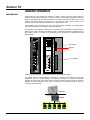
Using DF65 (Coprocessor module), users can implement a logic configuration through ladder
language and interact with all modules of the DFI302 system.
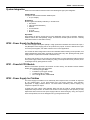
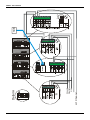
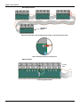
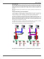
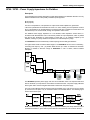
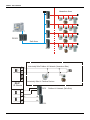
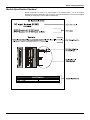
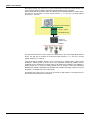
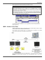
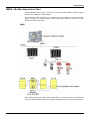
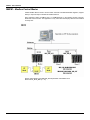
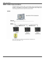
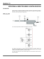
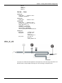
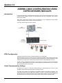
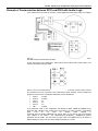
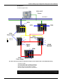
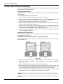
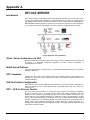
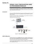
The picture below shows the system overview:
SYSCON
LOGIC VIEW
HMI
DFI/OLE Server
ETH
DFI302
and DF65
Coprocessor
Discrete Control
Continuous
Control
DFI302 System and Coprocessor
DF65 Configuration
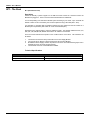
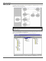
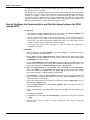
The DF65 Coprocessor uses the Logic View software for its configuration.
Remember that the DF51 (Processor) must be configured as a Master and the DF65 (Coprocessor)
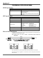
must be configured as a Slave. The physical connection between both is done via DF68 when using
a RS-232 port. Another option could be using the DF58 module to allow a RS-485 connection.
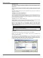
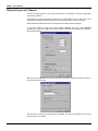
In order to set the configuration parameters of the DF65 it is necessary to put the communication
switch in the default position, just in case you have forgotten how the DF65 was set or it is the first
time you are testing this communication.
Serial Communication Settings
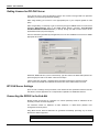
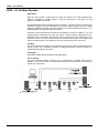
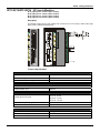
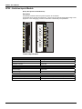
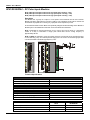
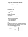
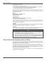
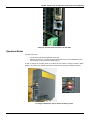
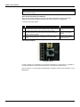
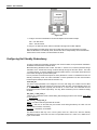
The DF65 has a group of 4 switches located between the communication ports. Using a small
screwdriver make sure that the lower switch is pointing to the left.
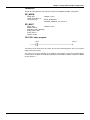
The switch in this position puts the DF65 on the Modbus default communication parameters. This
means that the Device ID, also called Device Address, is number 1, the baud rate is 9600 bps and
the parity bit is even. These parameters can be changed later using the Logic View software, but
they will only take effect when the Communication Switch is back to the Non-Default position.
13.1