1
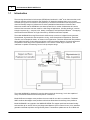
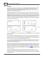
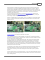
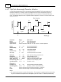
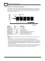
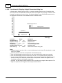
Appendix
249
Section 2. Power configuration
On unpacking the instrument the presence of the following should be noted.
1. Mains cable
2. Cell Lead
3. User Manual
4. Optional accessories if ordered (cells, electrodes, etc.)
The instrument is designed to operate at 110V or 220 V (+/-20%) AC power @ 50/60 Hz. Please check
the rear panel label for its input voltage setting. If an incorrect AC voltage is connected, the fuse will blow
and the instrument may be damaged.
The correct voltage and line frequency for your region have been set at our factory prior to shipment.
The standard 2 meter (or 6 foot) mains cable is fitted with an IEC type connector which can be plugged
directly into the power input on the rear panel of your instrument. The mains fuse (250V L 0.4A) is
housed within the power socket. When replacing the fuse, the user should fully disconnect the
instrument from the power supply.
In the event of repeat fuse failure, the user should consult CH Instruments, Inc. before proceeding further.
The unit should be placed within 1.5 m of a grounded mains power supply.
When the instrument is powered on, the indicator light on the front panel will be illuminated.
Rear panel of instrument
1.
2.
3.
4.
Power switch
On/off switch of unit
Fuse
State fuse value here
Power input socket
IEC type connection socket for mains cable
Cooling fan
Fuse rating = 0.8 A for 110V AC input, 0.4 A for 230V AC input
Power cord rating = 15 A for 110V AC input, 10 A for 230V AC input
All other features are clearly labeled on the rear panel itself.
© 2014 CH Instruments, Inc.