1
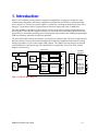
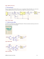
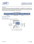
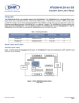
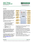
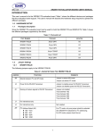
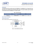
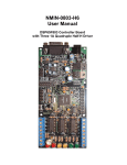
USB232 Converter User Manual Advantage-Lab GmbH Otto-Röhm-Strasse 69 64293 Darmstadt / Germany www.advantage-devices.com info@ advantage-lab.com v1 Copyright and Trademark Copyright 2009, Advantage-Devices . All rights reserved. No part of this manual may be reproduced or transmitted in any form for any purpose other than the purchaser's personal use, without the express written permission of Advantage-Devices . AdvantageDevices has made every effort to provide complete details about the product in this manual, but makes no warranty of any kind with regard to this material, including, but not limited to, the implied warranties of merchantability or fitness for a particular purpose. In no event shall AdvantageDevices . be liable for any incidental, special, indirect, or consequential damages whatsoever included but not limited to lost profits arising out of errors or omissions in this manual or the information contained herein. Advantage-Devices . products are not designed, intended, authorized or warranted for use as components in systems intended for surgical implant into the body, or in other applications intended to support or sustain life, or in any other application in which the failure of a Advantage-Devices . product could create a situation where personal injury, death, or severe property or environmental damage may occur. Advantage-Devices . reserves the right to discontinue or make changes to its products at any time without notice. Advantage-Devices and the Advantage-Devices logo, and combinations thereof are registered trademarks of Advantage-Devices . All other product names, company names, logos or other designations mentioned herein are trademarks of their respective owners. USB232 Converter is a trademark of Gridconnect. Advantage-Devices Otto-Röhm-Strasse 69 64293 Darmstadt, Germany Phone: +49 6151 6294871 Technical Support Phone: +49 6151 6294871 Fax: +49 6151 817329 On-line: www.Advantage-Devices.com 2 USB232 Converter User Guide Disclaimer and Revisions Date 02/05/10 09/08/10 01/06/10 Rev. Author A B C GR GR GR USB232 Converter User Guide Comments Preliminary Release Updates to drivers Updates to drivers i Warranty Advantage-Devices warrants each product to be free from defects in material and workmanship for a period of ONE YEAR after the date of shipment. During this period, if a customer is unable to resolve a product problem with Advantage-Devices Technical Support, a Return Material Authorization (RMA) will be issued. Following receipt of a RMA number, the customer shall return the product to Advantage-Devices , freight prepaid. Upon verification of warranty, AdvantageDevices will -- at its option -- repair or replace the product and return it to the customer freight prepaid. If the product is not under warranty, the customer may have Advantage-Devices repair the unit on a fee basis or return it. No services are handled at the customer's site under this warranty. This warranty is voided if the customer uses the product in an unauthorized or improper way, or in an environment for which it was not designed. Advantage-Devices warrants the media containing software and technical information to be free from defects and warrants that the software will operate substantially for a period of 60 DAYS after the date of shipment. In no event will Advantage-Devices be responsible to the user in contract, in tort (including negligence), strict liability or otherwise for any special, indirect, incidental or consequential damage or loss of equipment, plant or power system, cost of capital, loss of profits or revenues, cost of replacement power, additional expenses in the use of existing software, hardware, equipment or facilities, or claims against the user by its employees or customers resulting from the use of the information, recommendations, descriptions and safety notations supplied by Advantage-Devices . Advantage-Devices liability is limited (at its election) to: 1) refund of buyer's purchase price for such affected products (without interest) 2) repair or replacement of such products, provided that the buyer follows the above procedures. There are no understandings, agreements, representations or warranties, expressed or implied, including warranties of merchantability or fitness for a particular purpose, other than those specifically set out above or by any existing contract between the parties. The contents of this document shall not become part of or modify any prior or existing agreement, commitment or relationship. 4 USB232 Converter User Guide Contents Table of Contents 1. Introduction ...................................................................................................................... 1-1 1.1 USB-232 Features ............................................................................................... 1-2 1.2 Design Reference................................................................................................. 1-2 1.3 Driver Installation ................................................................................................ 1-3 1.3.1 Driver Installation Windows XP/Vista ................................................. 1-3 1.4 RS232 Interface ................................................................................................... 1-4 1.5 USB Interface ...................................................................................................... 1-4 1.5.1 USB Vendor ID ................................................................................... 1-4 1.5.2 USB Product ID ................................................................................... 1-4 1.6 UART Manager ................................................................................................... 1-5 1.6.1 Transmitter .......................................................................................... 1-5 1.6.2 Receiver .............................................................................................. 1-5 1.6.3 Automatic RTS/CTS Hardware Flow Control....................................... 1-5 1.6.4 Automatic DTR/DSR Hardware Flow Control...................................... 1-5 1.6.5 1.4.6Automatic XON/XOFF Software Flow Control ....................................... 1-6 1.7 Schematic ............................................................................................................ 1-6 1.7.1 USB Soft Connect................................................................................ 1-6 1.7.2 Transient Suppressor ........................................................................... 1-6 1.7.3 USB UART ......................................................................................... 1-7 1.7.4 Sleep Mode .......................................................................................... 1-7 1.7.5 RS232 Transceiver .............................................................................. 1-8 1.7.6 Power Supply....................................................................................... 1-9 1.7.7 RS232 Activity LEDs .......................................................................... 1-9 1.8 USB Cable Options............................................................................................ 1-10 1.9 Software Requirements...................................................................................... 1-10 List of Figures Figure 1-USB-232 Block Diagram ......................................................................................... 1-1 Figure 2-UART Block Diagram ............................................................................................. 1-5 Figure 3-Soft Start .................................................................................................................. 1-6 Figure 4-USB Transient Suppressor ....................................................................................... 1-6 Figure 5-USB UART .............................................................................................................. 1-7 Figure 6-RS232 Transceiver ................................................................................................... 1-9 Figure 7-Power Supply ........................................................................................................... 1-9 Figure 8-RXD LED ................................................................................................................ 1-9 Figure 9-TXD LED ................................................................................................................ 1-9 Figure 10-USB-232 with B Connector. ................................................................................. 1-10 USB232 Converter User Guide iii 1. Introduction RS232 is still commonly used by industrial equipment manufacturers. Its purpose is usually for setup, commissioning, diagnostics, and firmware upgrades to individual devices like PLCs, motion controllers, drives, sensors, etc. Usually, the systems engineer or technician is working out on the factory floor with a laptop PC. The problem is that it is getting harder to find a new laptop with legacy COMM ports. The usual solution is to purchase a USB to RS232 converter in the form of a dongle. Implementations to date using the FTDI or Prolific chip have not been very successful. The failure modes have been to either stop working, or to crash the operating system. Some laptops still available with COMM ports go through a USB layer internally and suffer from the same problems. The Exar USB UART hardware and software is by far the best solution to date. The Exar evaluation board has been tested by a major motion control distributor and found to be compatible with almost all existing and legacy products, as well as other vendor OEM products. The USB232 converter design uses the Exar evaluation board as a reference design. The optimized drivers supplied by Exar will be used. A block diagram is shown below. XR21V1410 Soft Start +3.3V Regulator Internal 48MHz Oscillator VBUS DM DP GND USB Device Interface Baud Rate Generator Internal Status and Control Registers 128-byte TX FIFO TX 384-byte RX FIFO RX MODEM I/O USB B-Type Connector RTS CTS DTR DSR CD RI RS232 Interface DB9 Male Connector RS232-TX 3 RS232-RX 2 RS232-RTS RS232-CTS RS232-DTR RS232-DSR RS232-CD RS232-RI 7 8 4 6 1 9 UART Figure 1-USB-232 Block Diagram USB232 Converter User Guide 1-1 1.1 USB-232 Features USB 2.0 Compliant Interface Supports 12 Mbps USB full-speed data rate Supports USB suspend, resume and remote wakeup operations USB Port Transient Suppressor Enhanced UART Features Data rates up to 12 Mbps 128 byte TX FIFO 384 byte RX FIFO 7, 8 or 9 data bits, 1 or 2 stop bits Automatic Hardware (RTS/CTS or DTR/DSR) Flow Control Automatic Software (Xon/Xoff) Flow Control Sleep Mode for reduced power Powered directly from USB LEDs for Power, TX and RX ESD protection diodes on RS232 lines Software drivers Windows 2000, XP, Vista, and Mac Optional EEPROM for vendor data 1.2 Design Reference The Exar USB-UART 1-Channel Evaluation Board was used as the reference design for the USB232 converter design. Exar XR21V1410IL16-QFN16 USB UART (V1410) Exar SP3244EEY-L-TSSOP-28 RS232 transceiver Exar SP6669AEK-L-TTR3-SOT23-5 Voltage regulator (or similar design) Inrush limiter DB9 with male pins wired as a DTE device. Interface Description 1-2 USB232 Converter User Guide 1.3 Driver Installation Software setup requires installing the USB232 device driver. The device driver allows the USB232 device to appear to the PC's application software as an additional COM port (in addition to any existing hardware COM ports). Application software running on the PC accesses the USB232 device as it would access a standard hardware COM port. However, actual data transfer between the PC and the USB232 device is performed over the USB. Therefore, existing COM port applications may be used to transfer data via the USB to the USB232-based device without modifying the application. All drivers are now supplied on the software CD. See the EXAR website for additional driver support for the XR21V1410. You can reach EXAR tech support at: [email protected] 1.3.1 Driver Installation Windows XP/Vista Follow these steps to install the Windows XP/Vista driver: 1. Connect the USB cable between the host computer and the USB232 target device. 2. Windows will open a “Found New Hardware Wizard” window. 3. Select “NO, not at this time” to have Windows connect to Windows Update to search for software. Click Next to continue. 4. The wizard will assist in installing software for XR21V1410 USB UART. 5. Select "Install from a list or specific location (Advanced)" and press Next. 6. Select "Include this location in the search". 7. Press Browse to locate the "D:\drivers\xp2kvista7" directory. Select “x64” folder for 64-bit systems or “x86” folder for 32-bit systems. Once the folder is selected press OK. 8. Verify that the correct path and filename are shown and click Next. 9. Verify the correct driver is selected. Click Next to continue. 10. If the Windows logo testing warning, click “Continue Anyway.” 11. Press Finish to finish installing the device drivers. 12. A popup will indicate the driver is installed and the device is ready to use. USB232 Converter User Guide 1-3 1.4 RS232 Interface The RS232 serial interface is through a DB9 Male connector wired according to the following table. Pin assignments are from the evaluation board schematics. PIN 9 8 7 6 5 4 3 2 1 CONNECTION Ring Indicator CTS RTS DSR Ground DTR TXD RXD Carrier Detect 1.5 USB Interface The standard unit comes with an 8” USB-A cable permanently attached to the circuit board. You can order a USB-232 unit with a USB connector that allows you to use any length USB cable. See USB Cable Options on page 1-10 The USB interface of the V1410 is compliant with the USB 2.0 Full-Speed Specifications. The USB configuration model presented by the V1410 to the device driver is compatible to the Abstract Control Model of the USB Communication Device Class (CDC-ACM). The V1410 uses the following set of parameters: 1 Control Endpoint Endpoint 0 as outlined in the USB specifications 1 Configuration is supported 2 interfaces for the UART channel Single interrupt endpoint Bulk-in and bulk-out endpoints 1.5.1 USB Vendor ID Exar’s USB Vendor ID is 0x04E2. This is the default Vendor ID that is used for the USB232 Converter. 1.5.2 USB Product ID The default USB Product ID for the USB232 Converter is 0x1410. 1-4 USB232 Converter User Guide 1.6 UART Manager The UART Manager enables/disables the UART including the TX and RX FIFOs. 1.6.1 Transmitter The transmitter consists of a 128-byte TX FIFO and a Transmit Shift Register (TSR). Once a bulk-out packet has been received and the CRC has been validated, the data bytes in that packet are written into the TX FIFO of the specified UART channel. Data from the TX FIFO is transferred to the TSR when the TSR is idle or has completed sending the previous data byte. The TSR shifts the data out onto the TX output pin at the data rate defined by the CLOCK_DIVISOR and TX_CLOCK_MASK registers. The transmitter sends the start bit followed by the data bits (starting with the LSB), inserts the proper parity-bit if enabled, and adds the stop-bit(s). The transmitter can be configured for 7 or 8 data bits with parity or 9 data bits with no parity. XR21V1410 Internal 48MHz Oscillator USB Device Interface Baud Rate Generator Internal Status and Control Registers 128-byte TX FIFO TX 384-byte RX FIFO RX MODEM I/O RTS CTS DTR DSR CD RI UART Figure 2-UART Block Diagram 1.6.2 Receiver The receiver consists of a 384-byte RX FIFO and a Receive Shift Register (RSR). Data that is received in the RSR via the RX pin is transferred into the RX FIFO along with any error tags such as Framing, Parity, Break and Overrun errors. Data from the RX FIFO can be sent to the USB host by sending a bulk-in packet. 1.6.3 Automatic RTS/CTS Hardware Flow Control Automatic RTS flow control is used to prevent data overrun errors in local RX FIFO by de-asserting the RTS signal to the remote UART. When there is room in the RX FIFO, the RTS pin will be re-asserted. Automatic CTS flow control is used to prevent data overrun to the remote RX FIFO. The CTS# input is monitored to suspend/restart the local transmitter. 1.6.4 Automatic DTR/DSR Hardware Flow Control Auto DTR/DSR hardware flow control behaves the same as the Auto RTS/CTS hardware flow control described above except that it uses the DTR# and DSR# signals. USB232 Converter User Guide 1-5 1.6.5 1.4.6Automatic XON/XOFF Software Flow Control When software flow control is enabled, the V1410 compares the receive data characters with the programmed Xon or Xoff characters. If the received character matches the programmed Xoff character, the V1410 will halt transmission as soon as the current character has completed transmission. Data transmission is resumed when a received character matches the Xon character. 1.7 Schematic The schematic can be broken into functional sections. 1.7.1 USB Soft Connect The soft connect circuit allows the unit to be connected without a large inrush current. Q1 is a P-channel MOSFET rated at 12V, 4.1A. The gate charge is controlled by C1 and R1. As the gate charge voltage is increased the channel opens to allow USB +5VDC on J1, pin 1 to be applied to other circuits. USB data is supplied on J1, pins 2 and 3. Figure 3-Soft Start 1.7.2 Transient Suppressor A USB Port Transient Suppressor (U2) circuit has been added to the USB data lines. The SN75240 is a dual transient voltage suppressor designed to provide electrical noise transient protection to Universal Serial Bus (USB) full−speed ports. Any cabled I/O can be subjected to electrical noise transients from various sources. These noise transients can cause damage to the USB transceiver and/or the USB ASIC if they are of sufficient magnitude and duration. USB ports are typically implemented in 3-V or 5-V digital CMOS with very limited ESD protection. The SN75240 can significantly increase the port ESD protection level and reduce the risk of damage to the circuits of the USB port. Figure 4-USB Transient Suppressor 1-6 USB232 Converter User Guide 1.7.3 USB UART The XR21V1410 (V1410) is an enhanced Universal Asynchronous Receiver and Transmitter (UART) with a USB interface. The USB interface is fully compliant to Full Speed USB 2.0 specification that supports 12 Mbps USB data transfer rate. The USB interface also supports USB suspend, resume and remote wakeup operations. The V1410 operates from an internal 48MHz clock therefore no external crystal/oscillator is required. With the fractional baud rate generator, any baud rate can accurately be generated using the internal 48MHz clock. The large 128-byte FIFO and 384-byte RX FIFO of the V1410 helps to optimize the overall data throughput for various applications. Software drivers for Windows 2000, XP, and Vista are supported for the XR21V1410. See the EXAR website for additional drivers. Figure 5-USB UART 1.7.4 Sleep Mode The XR21V will use the LPWR Low Power signal to shut down the RS232 transceiver and some internal circuits. This will save power when no data signals are active. The low power mode takes effect in about 30 seconds of idle time. See Figure 5-USB UART. USB232 Converter User Guide 1-7 1.7.5 RS232 Transceiver The SP3244E/3245E (or MAX3243) is a 3-driver/5-receiver device. These devices use an internal highefficiency, charge-pump power supply that requires only 0.1µF capacitors for 3.3V single-supply operation. This charge pump and Sipex’s driver architecture allow the SP3244E/3245E to deliver compliant RS-232 performance from a +5VDC power supply. The Auto On-line® Plus feature (shutdown) allows the device to automatically enter a low power shutdown mode if all receiver and driver inputs have been idle for 30 seconds. The device will “wake-up” from this automatic shutdown state upon detecting activity. This power saving feature functions without system intervention or modifications to software or drivers. SP3244E supports serial data rates of 250kbps minimum under full load and while maintaining slew rates of less than 30V/µs. SP3245E is capable of high speed communication of up to 1Mbps. ESD-protection structures are incorporated on all pins to protect against electrostatic discharges encountered during handling and assembly. The driver output and receiver inputs of the SP3244E/3245E have extra protection against static electricity. Sipex uses state-of-the-art structures to protect these pins against ESD of ±15kV without damage. The ESD structures withstand high ESD in all states: normal operation, shutdown, and powered down. After an ESD event, the SP3244E/3245E will keep working without latch-up or damage. The transmitter outputs and receiver inputs of the SP3244E/3245E are characterized for protection to the following limits: • ±15kV using the Human Body Model • ±8kV using the Contact Discharge method specified in IEC 1000-4-2 • ±15kV using the Air-Gap Discharge method specified in IEC 1000-4-2 1-8 USB232 Converter User Guide Figure 6-RS232 Transceiver 1.7.6 Power Supply The power supply converts USB +5VDC (J1, pin 1) to regulated 3.3VDC. The LM1117 is a more robust switching regulator than the one used in the reference design. D5 is an LED power indicator. Figure 7-Power Supply 1.7.7 RS232 Activity LEDs An LED has been added for the RXD and TXD data lines. LEDs are mounted so that the top sticks out of the case to provide a wide viewing angle. Figure 8-RXD LED Figure 9-TXD LED USB232 Converter User Guide 1-9 1.8 USB Cable Options The standard unit is supplied with an 8” USB-A cable with a strain relief. An optional USB-B connector can be installed on the circuit board. This will allow the user to plug in different lengths of USB cables. Contact Advantage-Devices sales to custom order the USB232 adapter. Figure 10-USB-232 with B Connector 1.9 Software Requirements COMM Port drivers are supplied by EXAR. The software CD contains this user manual and all current drivers. Go to the EXAR web site for additional driver information. You can reach EXAR tech support at: [email protected] 1-10 USB232 Converter User Guide