1
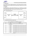
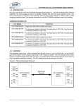
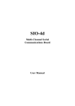
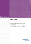
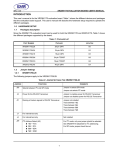
REV. 1.0.0
XR21V1414 EVALUATION BOARD USER’S MANUAL
1.0 INTRODUCTION
This user’s manual is for the XR21V1414 evaluation board. It will describe the hardware setup required to
operate the part.
2.0 OVERVIEW
The XR21V1414 evaluation board has one 48-TQFP package on it. Figure 1 shows a top view of XR21V1414
evaluation board layout.
FIGURE 1. TOP VIEW OF XR21V1414 EVALUATION BOARD LAYOUT
1
XR21V1414 EVALUATION BOARD USER’S MANUAL
Figure 2 shows a bottom view of XR21V1414 evaluation board layout.
FIGURE 2. BOTTOM VIEW OF XR21V1414 EVALUATION BOARD LAYOUT
2
REV. 1.0.0
XR21V1414 EVALUATION BOARD USER’S MANUAL
REV. 1.0.0
2.1
Evaluation Board Components
Table 1 below lists some of the components installed on the evaluation boards. The default setting is RS-232
mode.
TABLE 1: COMPONENTS OF THE XR21V1414 EVALUATION BOARD
UNIT
LOCATION
PART
FUNCTION
U1
Top
XRP6657IHBTR-F-DFN6
U2
Top
AT24C02B-PU-DIP8
U3
Top
XR21V1414IM48
U4
Bottom
NC7SZ14M5X-SOT-23-5
U5
Bottom
SN74LVC2G53DCTR-SM8
Switch UART TXA signal into either RS-232 or RS-485
transceiver.
U6
Bottom
SN74LVC2G53DCTR-SM8
Switch UART TXB signal into either RS-232 or RS-485
transceiver.
U7
Bottom
SN74LVC2G53DCTR-SM8
Switch RXA signal from either RS-232 or RS-485 transceiver.
U8
Bottom
SN74LVC2G53DCTR-SM8
Switch RXB signal from either RS-232 or RS-485 transceiver.
U9
Bottom
SN74LVC2G53DCTR-SM8
Switch UART TXC signal into either RS-232 or RS-485
transceiver.
U10
Bottom
SN74LVC2G53DCTR-SM8
Switch UART TXD signal into either RS-232 or RS-485
transceiver.
U11
Bottom
SN74LVC2G53DCTR-SM8
Switch RXC signal from either RS-232 or RS-485 transceiver.
U12
Bottom
SN74LVC2G53DCTR-SM8
Switch RXD signal from either RS-232 or RS-485 transceiver.
U13
Top
SP3245EEY-L-TSSOP-28
Exar’s RS-232 transceiver for channel A.
U14
Top
SP3245EEY-L-TSSOP-28
Exar’s RS-232 transceiver for channel B.
U15
Top
SP3245EEY-L-TSSOP-28
Exar’s RS-232 transceiver for channel C.
U16
Top
SP3245EEY-L-TSSOP-28
Exar’s RS-232 transceiver for channel D.
U17
Bottom
SN74LVC2G66DCT-SM8
Mutiplexer to select RS-485 direction control signal
(RTSA# or DTRA#).
U18
Top
SP3497EEN-L-NSOIC14
Exar’s RS-485 transceiver for channel A.
U19
Bottom
SN74LVC2G66DCT-SM8
Mutiplexer to select RS-485 direction control signal
(RTSB# or DTRB#).
U20
Top
SP3497EEN-L-NSOIC14
Exar’s RS-485 transceiver for channel B.
U21
Bottom
SN74LVC2G66DCT-SM8
Mutiplexer to select RS-485 direction control signal
(RTSC# or DTRC#).
U22
Top
SP3497EEN-L-NSOIC14
Exar’s RS-485 transceiver for channel C.
U23
Bottom
SN74LVC2G66DCT-SM8
Mutiplexer to select RS-485 direction control signal
(RTSD# or DTRD#).
Exar’s voltage converter to step down voltage from 5V to
3.3V.
I2C EEPROM.
Exar’s 4 channel USB UART.
Invert LowPower (suspend) signal.
3
XR21V1414 EVALUATION BOARD USER’S MANUAL
REV. 1.0.0
TABLE 1: COMPONENTS OF THE XR21V1414 EVALUATION BOARD
UNIT
LOCATION
PART
FUNCTION
U24
Top
SP3497EEN-L-NSOIC14
CON1
Top
PJ-002A
CON2
Top
690-004-621-023
USB B-Type connector. Communication with USB host
(USBD+, USBD-) and power source for evaluation board
(VBus).
CON3
Top
182-009-113R161
RS-232 mode DB9 male connector for channel A.
CON4
Top
182-009-113R161
RS-232 mode DB9 male connector for channel B.
CON5
Top
182-009-113R161
RS-232 mode DB9 male connector for channel C.
CON6
Top
182-009-113R161
RS-232 mode DB9 male connector for channel D.
CON7
Top
ED555/4DS
RS-485 mode 4X1 terminal block for channel A.
CON8
Top
ED555/4DS
RS-485 mode 4X1 terminal block for channel B.
CON9
Top
ED555/4DS
RS-485 mode 4X1 terminal block for channel C.
CON10
Top
ED555/4DS
RS-485 mode 4X1 terminal block for channel D.
Exar’s RS-485 transceiver for channel D.
External power input.
NOTES:1) An external pull-up is required on the LOWPOWER pin for proper functionality. The external pull-up is not shown
in the evaluation board schematics, but has been added on the evaluation board. 2) An external pull-up is required on any
GPIO pins that is used as an input. In the suspend mode, the internal pull-up resistor is disabled and the input will be
floating if there is no external pull-up resistor. The external pull-ups have not been added to the GPIOs used as inputs on
this evaluation board.
4
XR21V1414 EVALUATION BOARD USER’S MANUAL
REV. 1.0.0
2.2
Jumper Settings
2.2.1
Common jumpers
Common jumpers are those jumpers which should be set the same for both RS-232 and RS-485 mode. The
Table 2 shows the common jumpers setting on the evaluation board:
TABLE 2: COMMON JUMPERS SETTINGS
JUMPERS
LOCATION
FUNCTIONS
COMMENTS
JP1
Top
Power source select
Not installed. Trace between pin 2&3.
■ Jumper in 1&2 selects power from external power
supply of 5V
■ Jumper in 2&3 selects power from USB VBUS
power
JP2
Top
SCL pull-up/pull-down resistor select
Jumper in 1&2 selects pull-up for SCL
Jumper in 2&3 selects pull-down for SCL
JP3
Top
SDA pull-up/pull-down resistor select
Jumper in 1&2 selects pull-up for SDA
Jumper in 2&3 selects pull-down for SDA
JP4
Top
I2C EEPROM header
Jumper in 1&2 connects SCL to I2C EEPROM
Jumper in 3&4 connects SDA to I2C EEPROM
NOTE: I2C EEPROM has not been programmed
JP5
Top
Selects RS-232 or RS-485 mode for
Channel A
Jumper in 1&2 selects RS-485 mode
Jumper in 2&3 selects RS-232 mode (default)
JP6
Top
Selects RS-232 or RS-485 mode for
Channel B
Jumper in 1&2 selects RS-485 mode
Jumper in 2&3 selects RS-232 mode (default)
JP7
Top
Selects RS-232 or RS-485 mode for
Channel C
Jumper in 1&2 selects RS-485 mode
Jumper in 2&3 selects RS-232 mode (default)
JP8
Top
Selects RS-232 or RS-485 mode for
Channel D
Jumper in 1&2 selects RS-485 mode
Jumper in 2&3 selects RS-232 mode (default)
JP25
Top
Power supply for XR21V1414
Not installed. Trace between pin 1&2
JP26
Top
UART side Channel A external loopback header
Jumper in enables external loopback for channel A in the
UART side
NOTE: External loopback via this jumper can only be
performed when the transceiver has been
disabled.
JP27
Top
UART side Channel B external loopback header
Jumper in enables external loopback for channel B in the
UART side
NOTE: External loopback via this jumper can only be
performed when the transceiver has been
disabled.
5
XR21V1414 EVALUATION BOARD USER’S MANUAL
REV. 1.0.0
TABLE 2: COMMON JUMPERS SETTINGS
JUMPERS
LOCATION
JP28
Top
FUNCTIONS
COMMENTS
UART side Channel C external loopback header
Jumper in enables external loopback for channel C in the
UART side
NOTE: External loopback via this jumper can only be
performed when the transceiver has been
disabled.
JP29
Top
UART side Channel D external loopback header
Jumper in enables external loopback for channel D in the
UART side
NOTE: External loopback via this jumper can only be
performed when the transceiver has been
disabled.
2.2.2
Remote wakeup and jumper
The SDA and SCL are used to specify whether Remote Wakeup and/or Bus Powered configurations are to be
supported. These pins are sampled at power-up. The following Table 3 describes how Remote Wakeup and
Bus Powered support.
TABLE 3: REMOTE WAKEUP AND POWER MODES
SDA
SCL
REMOTE WAKE-UP
SUPPORT
POWER MODE
COMMENTS
1
1
No
Self-Powered
Default, if no EEPROM is present
1
0
No
Bus-Powered
0
1
Yes
Self-Powered
0
0
Yes
Bus-Powered
The following Table 4 shows jumpers related to remote wakeup.
TABLE 4: REMOTE WAKEUP JUMPERS SETTINGS
JUMPERS
LOCATION
FUNCTIONS
COMMENTS
JP38
Top
Select remote control wakeup signal for Jumper in 1&2 selects UART RS-232 transceiver (RI#)
Channel A
signal
Jumper in 2&3 selects push-button
SW1
Top
Generate remote wakeup signal
Push once to generate one remote wakeup signal
6
XR21V1414 EVALUATION BOARD USER’S MANUAL
REV. 1.0.0
2.2.3
RS-232 mode jumpers (Default setting is RS-232 mode)
The XR21V1414 evaluation board is set in RS-232 mode by default. The following Table 5 jumper settings
apply to the RS-232 mode:
TABLE 5: JUMPER SETTINGS FOR RS-232 MODE
JUMPERS
LOCATION
JP30
Top
Power supply for RS-232 transceiver of
Channel A
Not installed. Trace between pin 1&2
JP31
Top
Power supply for RS-232 transceiver of
Channel B
Not installed. Trace between pin 1&2
JP32
Top
Power supply for RS-232 transceiver of
Channel C
Not installed. Trace between pin 1&2
JP33
Top
Power supply for RS-232 transceiver of
Channel D
Not installed. Trace between pin 1&2
2.2.4
FUNCTIONS
COMMENTS
RS-485 mode jumpers
The following Table 6 jumper setting applies to the RS-485 mode:
TABLE 6: JUMPER SETTINGS FOR RS-485 MODE
JUMPERS
LOCATION
FUNCTIONS
COMMENTS
JP34
Top
Power supply for RS-485 transceiver of
Channel A
Not installed. Trace between pin 1&2
JP9
Top
Select Channel A RTS or DTR direction
control for TX
Jumper in 1&2 selects RTS based direction control for
TX
Jumper in 2&3 selects DTR based direction control for
TX
JP10
Top
Select Channel A direction control for RX Jumper in 1&2 selects common direction control for
and TX or always for RX
RX and TX
Jumper in 2&3 enables RX always
JP11
Top
Channel select for half duplex or full
duplex mode
Jumper in 1&2 selects for half duplex mode
Jumper in 2&3 selects for full duplex mode
JP12
Top
Channel select for half duplex or full
duplex mode
Jumper in 1&2 selects for half duplex mode
Jumper in 2&3 selects for full duplex mode
JP35
Top
Power supply for RS-485 transceiver of
Channel B
Not installed. Trace between pin 1&2
JP13
Top
Select Channel B RTS or DTR direction
control for TX
Jumper in 1&2 selects RTS based direction control for
TX
Jumper in 2&3 selects DTR based direction control for
TX
JP14
Top
Select Channel B direction control for RX Jumper in 1&2 selects common direction control for
and TX or always for RX
RX and TX
Jumper in 2&3 selects common direction control for
RX always
JP15
Top
Channel B select for half duplex or full
duplex mode
7
Jumper in 1&2 selects for half duplex mode
Jumper in 2&3 selects for full duplex mode
XR21V1414 EVALUATION BOARD USER’S MANUAL
REV. 1.0.0
TABLE 6: JUMPER SETTINGS FOR RS-485 MODE
JUMPERS
LOCATION
FUNCTIONS
COMMENTS
JP16
Top
Channel B select for half duplex or full
duplex mode
Jumper in 1&2 selects for half duplex mode
Jumper in 2&3 selects for full duplex mode
JP36
Top
Power supply for RS-485 transceiver of
Channel C
Not installed. Trace between pin 1&2
JP17
Top
Select Channel C RTS or DTR direction
control for TX
Jumper in 1&2 selects RTS based direction control for
TX
Jumper in 2&3 selects DTR based direction control for
TX
JP18
Top
Select Channel C direction control for RX Jumper in 1&2 selects common direction control for
and TX or always for RX
RX and TX
Jumper in 2&3 selects common direction control for
RX always
JP19
Top
Channel C select for half duplex or full
duplex mode
Jumper in 1&2 selects for half duplex mode
Jumper in 2&3 selects for full duplex mode
JP20
Top
Channel C select for half duplex or full
duplex mode
Jumper in 1&2 selects for half duplex mode
Jumper in 2&3 selects for full duplex mode
JP37
Top
Power supply for RS-485 transceiver of
Channel D
Not installed. Trace between pin 1&2
JP21
Top
Select Channel D RTS or DTR direction
control for TX
Jumper in 1&2 selects RTS based direction control for
TX
Jumper in 2&3 selects DTR based direction control for
TX
JP22
Top
Select Channel D direction control for RX Jumper in 1&2 selects common direction control for
and TX or always for RX
RX and TX
Jumper in 2&3 selects common direction control for
RX always
JP23
Top
Channel D select for half duplex or full
duplex mode
Jumper in 1&2 selects for half duplex mode
Jumper in 2&3 selects for full duplex mode
JP24
Top
Channel D select for half duplex or full
duplex mode
Jumper in 1&2 selects for half duplex mode
Jumper in 2&3 selects for full duplex mode
3.0 DRIVERS AND SUPPORT
For any questions about this evaluation board, software drivers or technical support, send an e-mail to
[email protected].
8
REV. 1.0.0
XR21V1414 EVALUATION BOARD USER’S MANUAL
NOTICE
EXAR Corporation reserves the right to make changes to the products contained in this publication in order to
improve design, performance or reliability. EXAR Corporation assumes no responsibility for the use of any
circuits described herein, conveys no license under any patent or other right, and makes no representation that
the circuits are free of patent infringement. Charts and schedules contained here in are only for illustration
purposes and may vary depending upon a user’s specific application. While the information in this publication
has been carefully checked; no responsibility, however, is assumed for inaccuracies.
EXAR Corporation does not recommend the use of any of its products in life support applications where the
failure or malfunction of the product can reasonably be expected to cause failure of the life support system or
to significantly affect its safety or effectiveness. Products are not authorized for use in such applications unless
EXAR Corporation receives, in writing, assurances to its satisfaction that: (a) the risk of injury or damage has
been minimized; (b) the user assumes all such risks; (c) potential liability of EXAR Corporation is adequately
protected under the circumstances.
Copyright 2009 EXAR Corporation
Datasheet July 2009.
Send your UART technical inquiry with technical details to hotline: [email protected].
Reproduction, in part or whole, without the prior written consent of EXAR Corporation is prohibited.
9