1
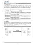
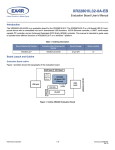
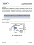
XR21B1411 USER’S MANUAL
WEB CONFIGURATION TOOL USER’S MANUAL
REV. 1.0.0
1
XR21B1411 USER’S MANUAL
WEB CONFIGURATION TOOL USER’S MANUAL
REV. 1.0.0
TABLE OF CONTENTS
1.0 OVERVIEW............................................................................................................................................... 3
2.0 GPIO PIN CONFIGURATIONS ................................................................................................................ 3
2.1 CONFIGURING THE GPIO PINS IN GPIO MODE .............................................................................................. 3
2.1.1 CONFIGURING GPIO INPUTS .......................................................................................................................................
2.1.1.1 ENABLING INTERNAL PULL-UP OR PULL-DOWN RESISTORS .......................................................................................
2.1.1.2 ENABLING GPIO INTERRUPTS .................................................................................................................................
2.1.2 CONFIGURING GPIO OUTPUTS ...................................................................................................................................
4
4
4
5
2.2 CONFIGURING THE GPIO PINS IN AUTO RTS/CTS FLOW CONTROL MODE .............................................. 6
2.3 CONFIGURING THE GPIO PINS IN AUTO DTR/DSR FLOW CONTROL MODE.............................................. 7
2.4 CONFIGURING THE GPIO PINS IN AUTO HALF-DUPLEX TRANSCEIVER ENABLE MODE ........................ 8
3.0 USB CONFIGURATIONS......................................................................................................................... 9
3.1 ENTERING A VALID VENDOR ID AND PRODUCT ID....................................................................................... 9
3.2 USB MANUFACTURER, PRODUCT, SERIAL NUMBER STRINGS................................................................ 10
3.3 REMOTE WAKE-UP SUPPORT........................................................................................................................ 10
3.4 SELECTING THE POWER MODE..................................................................................................................... 10
3.5 USB MAX POWER............................................................................................................................................. 10
3.6 LOWPOWER PIN POLARITY............................................................................................................................ 10
4.0 UART SETTING CONFIGURATIONS.................................................................................................... 11
4.1 SELECTING THE CORE CLOCK FREQUENCY .............................................................................................. 12
4.2 SELECTING THE UART DEFAULT SETTINGS ............................................................................................... 12
5.0 CHECK DESIGN AND GENERATE CONFIGURATION FILE............................................................... 12
6.0 XR21B1411 SOFTWARE DRIVER AND OTP PROGRAMMING TOOL ............................................... 13
7.0 TECHNICAL SUPPORT ......................................................................................................................... 14
2
XR21B1411 USER’S MANUAL
WEB CONFIGURATION TOOL USER’S MANUAL
REV. 1.0.0
1.0 OVERVIEW
The XR21B1411 Enhanced 1-Channel Full-Speed USB UART has internal One-Time-Programmable (OTP)
memory that can be used to customize the default settings of the XR21B1411. The web configuration tool for
the XR21B1411 from Exar I/O Lab is shown above and can be accessed from a link on the XR21B1411
product page on Exar’s website. This tool shows a visual representation of how the device will behave upon
power-up such as the GPIO settings, UART settings and USB parameters (ie. Vendor ID, Product ID, Device
Maximum Power, etc.). Once the XR21B1411 has been configured using this tool, the design configuration
can be downloaded and used as an input file for Exar’s OTP programming tool (also available from Exar’s
website) to program the XR21B1411 device.
This manual provides instruction for configuring the XR21B1411 and provides notes/tips for the various
settings that are available. Note that once the XR21B1411 is programmed, no further changes or modifications
can be made to the OTP.
2.0 GPIO PIN CONFIGURATIONS
There are 4 modes available for the GPIO pins. Details of these 4 modes can be found in the XR21B1411
datasheet on Exar’s website. The 4 modes that can be selected are:
■
GPIO Mode
■
Auto RTS/CTS HW Flow Control
■
Auto DTR/DSR HW Flow Control
■
Auto Half-Duplex Transceiver Enable (typically used for RS-485)
2.1
Configuring the GPIO pins in GPIO Mode
There are 6 GPIO pins on the XR21B1411. By default, they are General Purpose I/Os that can be configured
either as inputs or outputs. In this mode, the defaults for the GPIOs are:
■
Inputs
■
Internal pull-up and pull-down resistors disabled
■
Interrupts are enabled for GPIOs configured as inputs
3
XR21B1411 USER’S MANUAL
WEB CONFIGURATION TOOL USER’S MANUAL
2.1.1
2.1.1.1
REV. 1.0.0
Configuring GPIO inputs
Enabling internal pull-up or pull-down resistors
As an input, a GPIO can have either an internal pull-up or pull-down resistor enabled. The pull-up or pull-down
resistor for an input can be configured by clicking on "PU" or "PD" for the desired GPIO input pins (shown in
the green circles in the image above). If enabled, the "PU" or "PD" will turn yellow for "enabled". Note that the
configuration tool will not allow both to be enabled at the same time. The last block clicked, "PU" or "PD", will
determine if the GPIO has an internal pull-up or pull-down resistor enabled. Clicking on the "PU" and "PD"
blocks will not have any effects if the GPIO is an output. Also, changing an input to an output will clear any
"PU" or "PD" block that has been enabled for that GPIO.
2.1.1.2
Enabling GPIO interrupts
By default, the GPIO interrupts are enabled. Any GPIO that is an input will generate an interrupt when its input
state changes. The GPIO interrupt can be disabled by clicking on the GPIOs in the purple circle in the image
above. If a GPIO is configured as an output, the interrupt will automatically be disabled for that GPIO.
4
XR21B1411 USER’S MANUAL
WEB CONFIGURATION TOOL USER’S MANUAL
REV. 1.0.0
2.1.2
Configuring GPIO outputs
By clicking on the arrows highlighted with the red circle above, the GPIOs will change from inputs to outputs as
shown in the image below. Once the GPIO is an output, the block next to the output arrow will turn yellow and
display "0" indicating that the default output state will be low upon power-up. Clicking on the this block will
change it to a "1" indicating that the default output state will be high upon power-up. An example of this is
shown below for GPIO2.
5
XR21B1411 USER’S MANUAL
WEB CONFIGURATION TOOL USER’S MANUAL
2.2
REV. 1.0.0
Configuring the GPIO Pins in Auto RTS/CTS Flow Control Mode
In Auto RTS/CTS flow control mode, GPIO5/RTS# becomes an output pin and GPIO4/CTS# becomes an input
pin. GPIO5/RTS# can not be changed to an input and, similarly, GPIO4/CTS# can not be changed to an
output. The configuration is shown below.
In this mode, GPIO3-GPIO0 can still be configured as described in “Section 2.1, Configuring the GPIO pins
in GPIO Mode” on page 1.
6
XR21B1411 USER’S MANUAL
WEB CONFIGURATION TOOL USER’S MANUAL
REV. 1.0.0
2.3
Configuring the GPIO Pins in Auto DTR/DSR Flow Control Mode
Auto DTR/DSR Flow Control Mode is similar to Auto RTS/CTS Flow Control Mode. In this mode, GPIO3/DTR#
is configured as an output and GPIO2/DSR# is configured as an input and their direction can not be changed.
The Auto DTR/DSR Flow Control configuration is shown below.
In this mode, GPIO5, GPIO4, GPIO1, and GPIO0 can still be configured as described in “Section 2.1,
Configuring the GPIO pins in GPIO Mode” on page 1.
7
XR21B1411 USER’S MANUAL
WEB CONFIGURATION TOOL USER’S MANUAL
2.4
REV. 1.0.0
Configuring the GPIO Pins in Auto Half-Duplex Transceiver Enable Mode
The Auto Half-Duplex Transceiver enable mode is typically used in half-duplex RS-485 applications. In this
mode the GPIO5/RTS# pin is used to control the driver enable of an RS-485 transceiver. When this mode is
selected, the polarity will also need to be selected as active high or active low.
■
Active High - The GPIO5/RTS# pin will be low when the UART is not transmitting data and the GPIO5/
RTS# pin will be high when the UART is transmitting data.
■
Active Low - The GPIO5/RTS# pin will be high when the UART is not transmitting data and the GPIO5/
RTS# pin will be low when the UART is transmitting data.
An example of how the Auto Half-Duplex Transceiver enable mode is shown below. The block next to the "TX
EN" also shows whether the selected polarity is active high or active low.
In this mode, GPIO4-GPIO0 can still be configured as described in “Section 2.1, Configuring the GPIO pins
in GPIO Mode” on page 1.
8
XR21B1411 USER’S MANUAL
WEB CONFIGURATION TOOL USER’S MANUAL
REV. 1.0.0
3.0 USB CONFIGURATIONS
By clicking on the "USB" block, an additional configuration window will appear on the right hand side of the
screen, as shown below.
3.1
Entering a Valid Vendor ID and Product ID
In this new window, the USB parameters can be entered. The configuration tool will have defaults of 0x0000 in
the Vendor ID (VID) and Product ID (PID) field. A VID or PID of 0x0000 is not an acceptable and will reported
later as an error when the "Check Design" button is pressed if valid IDs have not been entered. If using Exar’s
VID (0x04E2) and PID (0x1411), these values will need to be entered. A unique range of PIDs can be
requested from Exar by sending an e-mail request to [email protected].
9
XR21B1411 USER’S MANUAL
WEB CONFIGURATION TOOL USER’S MANUAL
3.2
REV. 1.0.0
USB Manufacturer, Product, Serial Number Strings
The default Manufacturer String is "Exar" and Product String is "XR21B1411" if no string values have been
entered. There is no default value for the Serial Number String. If one string is entered, then all three strings
need to be updated or they will not have a value when the OTP is programmed. Entering a value for the Serial
Number String is optional.
3.3
Remote Wake-up Support
By default, remote wake-up support is enabled. This can be disabled by unchecking the box. Note that if the
software driver does not have the remote wake-up feature enabled, then the XR21B1411 will not issue a
remote wake-up signal when a remote wake-up event occurs. Note that the standard CDC-ACM driver does
not support the Remote Wake-up feature.
3.4
Selecting the Power Mode
By default, bus-powered mode is enabled. The XR21B1411 can be configured for self-powered mode by
checking the box next to "Self Powered". For self-power mode, it is recommended that the box next to "Enable
VBUS Sense" also be checked. The VBUS Sense feature disables the internal pull-up resistor on the USBD+
pin when there is no power on the VBUS pin. This is required for USB compliance. If the VBUS Sense feature
is not available, then an external mechanism is required to disable the power supply to the XR21B1411.
3.5
USB Max Power
By default, the USB maximum power is configured as 100 mA. This is the maximum for a low power device, as
described in the USB specifications. Any board that requires more than 100 mA from VBUS will be considered
a high power device. The maximum allowable supply current is 500 mA for a high power device. The USB
max power can be changed by clicking on the arrows on either end of the scroll bar or by dragging the
horizontal scroll bar.
3.6
LOWPOWER Pin Polarity
The default polarity of the LOWPOWER pin (pin 1) is active high as shown in the drawing. The polarity can be
changed by clicking on the box below the USB block in the drawing. The inner circle will become yellow to
indicate that the LOWPOWER pin is now active low.
10
XR21B1411 USER’S MANUAL
WEB CONFIGURATION TOOL USER’S MANUAL
REV. 1.0.0
4.0 UART SETTING CONFIGURATIONS
Clicking on the "UART" block will remove the USB Configuration window and display the "UART Configuration
Window" as shown below.
11
XR21B1411 USER’S MANUAL
WEB CONFIGURATION TOOL USER’S MANUAL
4.1
REV. 1.0.0
Selecting the Core Clock Frequency
The available core clock frequencies are 6 MHz, 12 MHz, 24 MHz and 48 MHz. The selection of the core clock
frequency will affect the maximum baud rate and the power consumption. The maximum baud rate can be
calculated by dividing the core clock frequency by 4.
■
6 MHz core clock frequency => 1.5 Mbps maximum baud rate
■
12 MHz core clock frequency => 3 Mbps maximum baud rate
■
24 MHz core clock frequency => 6 Mbps maximum baud rate
■
48 MHz core clock frequency => 12 Mbps maximum baud rate
For details of how much power the XR21B1411 consumes with each core clock frequency, refer to the
XR21B1411 datasheet on Exar’s website. Note that the higher the core clock frequency, the more power it
consumes. If an application is battery-powered, it will be beneficial to use a 6 MHz core clock frequency if
baud rates above 1.5 Mbps do not need to be supported.
4.2
Selecting the UART default settings
Default baud rates and character formats can be entered and selected. Most standard software drivers and
applications will typically initialize the UART settings. However, this may be helpful for custom software drivers
and/or software applications that do not initialize/configure the UART settings.
5.0 CHECK DESIGN AND GENERATE CONFIGURATION FILE
Once all of the desired configurations have been entered or selected, click on the "Check Design" button. This
will check to see if there are any errors. If there are errors, then a pop-up message, as shown below, will
appear indicating the error and a button to go back to the correct page to fix it.
12
XR21B1411 USER’S MANUAL
WEB CONFIGURATION TOOL USER’S MANUAL
REV. 1.0.0
In this example, the VID and PID were not entered. Clicking on "Back to USB" will bring up the "USB
Configuration" block where the VID and PIDs can be entered. Once the error has been fixed, click "Check
Design" again. If there are no errors, then a pop-up window similar to the one below will appear.
Click on "Download Design File" to view and save the generated file. The file will have a ".xml" extension. This
saved file can be used at a later date by loading it using the "Load an Existing Design" block.
6.0 XR21B1411 SOFTWARE DRIVER AND OTP PROGRAMMING TOOL
The XR21B1411 Software Driver and OTP Programming Tool can be downloaded from Exar’s website. The
software driver needs to be installed before the OTP Programming Tool can be used. It is recommended that
the configuration be carefully reviewed before programming the OTP memory. Once the OTP memory has
been programmed, it can not be un-programmed. It is also recommended that samples be programmed and
tested before programming in volume.
13
XR21B1411 USER’S MANUAL
WEB CONFIGURATION TOOL USER’S MANUAL
REV. 1.0.0
7.0 TECHNICAL SUPPORT
If there are any questions about the web configuration tool, configuration file or the XR21B1411, send your
questions to [email protected].
NOTICE
EXAR Corporation reserves the right to make changes to the products contained in this publication in order to
improve design, performance or reliability. EXAR Corporation assumes no responsibility for the use of any
circuits described herein, conveys no license under any patent or other right, and makes no representation that
the circuits are free of patent infringement. Charts and schedules contained here in are only for illustration
purposes and may vary depending upon a user’s specific application. While the information in this publication
has been carefully checked; no responsibility, however, is assumed for inaccuracies.
EXAR Corporation does not recommend the use of any of its products in life support applications where the
failure or malfunction of the product can reasonably be expected to cause failure of the life support system or
to significantly affect its safety or effectiveness. Products are not authorized for use in such applications unless
EXAR Corporation receives, in writing, assurances to its satisfaction that: (a) the risk of injury or damage has
been minimized; (b) the user assumes all such risks; (c) potential liability of EXAR Corporation is adequately
protected under the circumstances.
Copyright 2010 EXAR Corporation
Datasheet September 2010.
Send your UART technical inquiry with technical details to hotline: [email protected].
Reproduction, in part or whole, without the prior written consent of EXAR Corporation is prohibited.
14