1
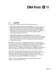
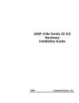
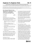
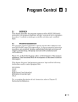
Host Interface Port
7.1
7
OVERVIEW
The host interface port (HIP) of the ADSP-2111, ADSP-2171, and
ADSP-21msp58/59 is a parallel I/O port that allows these processors to be
used as memory-mapped peripherals of a host computer (i.e. slave DSP
processors). Examples of host computers include the Intel 8051, Motorola
68000 family, and even other ADSP-21xx processors.
The host interface port can be thought of as an area of dual-ported
memory, or mailbox registers, that allow communication between the host
and the processor core of the ADSP-21xx. The host addresses the HIP as a
segment of 8- or 16-bit words of memory. To the processor core, the HIP is
a group of eight data-memory-mapped registers.
Any number of ADSP-21xx processors can be used in parallel as memorymapped peripherals. Assigning a different address location to each one
allows the host to control them all.
The operating speed of the HIP is similar to that of the processor data bus.
A read or write operation can occur within a single instruction cycle.
Because the HIP is normally connected with devices that are much slower
(the 68000, for example, can take four cycles to perform a bus operation),
the data transfer rate is usually limited by the host computer.
The host interface port is completely asynchronous to the rest of the
ADSP-21xx’s operations. The host can write data to or read data from the
HIP while the ADSP-21xx is operating at full speed. The HIP can be
configured for operation on an 8-bit or 16-bit data bus and for either a
multiplexed address/data bus or separate address and data buses.
The ADSP-2111, ADSP-2171, and ADSP-21msp58/59 support two types of
booting operations. One method boots from external memory (usually
EPROM) using the boot memory interface described in the “Memory
Interface” chapter. The other method uses the HIP to boot load a program
from the host computer. HIP booting is described at the end of this
chapter.
7–1
7 Host Interface Port
7.2
SUMMARY
HIP PIN
The HIP consists of 27 pins. As shown in Table 7.1, 16 of these are data
pins and 11 are control pins. Some of the control pins have dual functions,
allowing the processor to support different bus protocols.
Pin
Name
Number
of Pins Direction
HSEL
1
Input
HIP Select
HACK
1
Output
HIP Acknowledge
HSIZE
1
Input
HIP 8/16 Bit Host
0=16-bit; 1=8-bit
BMODE
1
Input
HIP Boot Mode Select
0=normal (EPROM); 1=HIP
HMD0
1
Input
HIP Bus Strobe Select
0=RD, WR; 1=RW, DS
HRD/HRW *
1
Input
HIP Read Strobe/
Read/Write Select
HWR/HDS *
1
Input
HIP Write Strobe/
Host Data Strobe
HMD1
1
Input
HIP Address/Data Mode
0=separate; 1=multiplexed
HD15-0/HAD15-0 **
16
Bidirectional
HIP Data/Address & Data
HA2 /ALE **
1
Input
HIP Host Address 2/
Address Latch Enable
HA1-0/no function **
2
Input
Host Addresses 1 & 0
TOTAL
27
* HMD0 selects function
** HMD1 selects function
Table 7.1 Host Interface Port Pins
7–2
Function
Host Interface Port 7
HSEL is a host select which allows the host to enable or disable the HIP for
host data transfers.
HACK is a host acknowledge output for hosts that require an acknowledge
for handshaking.
HSIZE configures the bus size; the HIP can function in both 8-bit and 16bit modes. If the HIP is configured for an 8-bit host (HSIZE=1), data is
read from and written to the lower eight bits of a HIP data register and the
upper eight bits are zero-filled (on host writes) or tristated (on host reads).
BMODE determines whether booting occurs through the HIP or through
the memory interface pins.
HMD0 and HMD1 are mode pins that configure the address, data and
strobe pins, as shown in Table 7.2. HMD0 configures the bus strobes,
selecting either separate read and write strobes or a single read/write
select and a host data strobe. HMD1 configures the bus protocol, selecting
either separate address (3-bit) and data (16-bit) buses or a multiplexed 16bit address/data bus with address latch enable. The timings of each of the
four bus protocols are described later in this chapter.
HMD1=0
HMD0=0
HMD0=1
HMD1=1
HRD
HWR
HD15-0
HA2-0
HIP Read Strobe
HIP Write Strobe
HIP Data
HIP Address
HRD
HWR
HAD15-0
ALE
HIP Read Strobe
HIP Write Strobe
HIP Address/Data
HIP Address Latch Enable
HRW
HDS
HD15-0
HA2-0
HIP Read/Write Select
HIP Data Strobe
HIP Data
HIP Address
HRW
HDS
HAD15-0
ALE
HIP Read/Write Select
HIP Data Strobe
HIP Address/Data
HIP Address Latch Enable
Table 7.2 HIP Configuration Modes
7–
3
7 Host Interface Port
The functions of the following pins are determined by HMD0 and HMD1
as described above:
HD15-0/HAD15-0 are either a data bus or a multiplexed address/data
bus. (Only the 3 least significant address bits are used.)
HRD/HRW is either a read strobe or a read/write select (1=read, 0=write).
HWR/HDS is either a write strobe or a data strobe.
HA2/ALE is either the most significant host address bit or an address
latch enable.
HA1-0 are either the two least significant host address bits or are unused.
7.3
FUNCTIONAL DESCRIPTION
HIP
The HIP consists of three functional blocks, shown in Figure 7.1: a host
control interface block (HCI), a block of six data registers (HDR5-0) and a
block of two status registers (HSR7-6). The HIP also includes an associated
HMASK register for masking interrupts generated by the HIP. The HCI
provides the control for reading and writing the host registers. The two
status registers provide status information to both the host and the ADSP21xx core.
The HIP data registers HDR5-0 are memory-mapped into internal data
memory at locations 0x3FE0 (HDR0) to 0x3FE5 (HDR5). These registers
can be thought of as a block of dual-ported memory. None of the HDRs
are dedicated to either direction; they can be read or written by either the
host or the ADSP-21xx. When the host reads an HDR register, a maskable
HIP read interrupt is generated. When the host writes an HDR, a
maskable HIP write interrupt is generated.
The read/write status of the HDRs is also stored in the HSR registers.
These status registers can be used to poll HDR status. Thus, data transfers
through the HIP can be managed by using either interrupts or a polling
scheme, described later in this chapter.
7–4
Host Interface Port 7
HSIZE
BMODE
HMD1
HMD0
HACK
Boot
Control
Host
Control
Interface
HSEL
HWR/HDS
HRD/HRW
HA2/ALE
HA1-0
2
Overwrite Bit
16
Read/write control
DMD BUS
HDR0
HDR1
HDR2
HDR3
HDR4
HMASK
SOFT RESET
HDR5
HSR6
HSR7
2
HIP
INTERRUPTS
16
HD15-0
Figure 7.1 HIP Block Diagram
The HSR registers are shown in Figure 7.2, which can be found on the
following page. Status information in HSR6 and HSR7 shows which HDRs
have been written. The lower byte of HSR6 shows which HDRs have been
written by the host computer. The upper byte of the HSR6 shows which
HDRs have been written by the ADSP-21xx. When an HDR register is
read, the corresponding HSR bit is cleared.
7–
5
7 Host Interface Port
HSR7
15 14 13 12 11 10 9
8
7
6
5
4
3
2
1
0
0
0
1
0
0
0
0
0
0
0
0
0
0
0
0
0
0x3FE7
21xx HDR0 Write
21xx HDR1 Write
21xx HDR2 Write
OVERWRITE
MODE
21xx HDR3 Write
21xx HDR4 Write
SOFTWARE
RESET
HSR6
21xx HDR5 Write
15 14 13 12 11 10
9
8
7
6
5
4
3
2
1
0
0
0
0
0
0
0
0
0
0
0
0
0
0
0
0
0
0x3FE6
Host HDR0 Write
Host HDR1 Write
21xx HDR5 Write
Host HDR2 Write
21xx HDR4 Write
Host HDR3 Write
21xx HDR3 Write
Host HDR4 Write
21xx HDR2 Write
Host HDR5 Write
21xx HDR1 Write
21xx HDR0 Write
Figure 7.2 HIP Status Registers
The lower six bits of HSR7 are copied from the upper byte of HSR6 so that
8-bit hosts can read both sets of status. Bits 7 and 6 of HSR7 control the
overwrite mode and software reset, respectively; these functions are
described later in this chapter. The upper byte of HSR7 is reserved. All
reserved bits and the software reset bit read as zeros. The overwrite bit is
the only bit in the HSRs that can be both written and read. At reset, all
HSR bits are zeros except for the overwrite bit, which is a one.
7.4
HIP OPERATION
The ADSP-21xx core can place a data value into one of the HDRs for
retrieval by the host computer. Similarly, the host computer can place a
data value into one of the HDRs for retrieval by the ADSP-21xx. To the
host computer, the HDRs function as a section of memory. To the
ADSP-21xx, the HDRs are memory-mapped registers, part of the internal
data memory space.
7–6
Host Interface Port 7
Because the HIP typically communicates with a host computer that has
both a slower instruction rate and a multicycle bus cycle, the host
computer is usually the limiting factor in the speed of HIP transfers.
During a transfer, the ADSP-21xx executes instructions normally,
independent of HIP operation. This is true even during a multicycle
transfer from the host.
For host computers that require handshaking, the ADSP-21xx returns
HACK in the same cycle as the host access, except in overwrite mode. In
overwrite mode, the ADSP-21xx can extend a host access by not asserting
the HACK acknowledge until the cycle is complete. The user can enable
and disable overwrite mode by setting and clearing a bit in HSR7.
Overwrite mode is described in more detail later in this chapter.
The HDRs are not initialized during either hardware or software reset.
The host can write information to the HDRs before a reset, and the ADSP21xx can read this information after the reset is finished. During reset,
however, HIP transfers cannot occur; the HACK pin is deasserted and the
data pins are tristated.
Because a host computer that requires handshaking must wait for an
acknowledgement from the ADSP-21xx, it is possible to cause such a host
to hang. If, when the host has initiated a transfer, but has not yet received
an acknowledgement, the ADSP-21xx is reset, then the acknowledgement
can not be generated, thus causing the host to wait indefinitely.
There is no hardware in the HIP to prevent the host from writing a
register that the ADSP-21xx core is reading (or vice versa). If the host and
the ADSP-21xx try to write the same register at the same time, the host
takes precedence. Simultaneous writes should be avoided, however: since
the ADSP-21xx and the host operate asynchronously, simultaneous writes
can cause unpredictable results.
7.4.1
Polled Operation
Polling is one method of transferring data between the host and the
ADSP-21xx. Every time the host writes to an HDR, a bit is automatically
set in the lower byte of HSR6. This bit remains set until the ADSP-21xx
reads the HDR. Similarly, when the ADSP-21xx writes to an HDR, a bit in
the upper byte of HSR6 (and the lower byte of HSR7) is set. This bit is
cleared automatically when the host reads the HDR.
7–
7
7 Host Interface Port
For example, the ADSP-21xx can wait in a loop reading an HSR bit to see
if the host has written new data. When the ADSP-21xx sees that the bit is
set, it conditionally jumps out of the loop, processes the new data, then
returns to the loop. When transferring data to the host, the ADSP-21xx
waits for the host to read the last data written so that new data can be
transferred. The host polls the HSR bits to see when the new data is
available.
7.4.1.1 HIP Status Synchronization
Processes running on the ADSP-21xx are asynchronous to processes
running on the host. Values in the shared status registers (HSR6, HSR7)
can therefore change at any time, and reading a changing value could give
unpredictable results. The ADSP-21xx HIP, however, includes
synchronization circuitry which guarantees that the HIP status is constant
during a read by either the ADSP-21xx core or the host. This
synchronization is illustrated in Figures 7.3 and 7.4. The status registers
are updated by the ADSP-21xx and thus are synchronous with the ADSP21xx processor clock, but host accesses are asynchronous with respect to
the ADSP-21xx clock.
When the host reads HSR6 or HSR7 to obtain status information, there is a
one-cycle synchronization delay before the current (i.e. updated) status is
available. To obtain the correct, current status, therefore, the host must perform
Host
Access
HCLK
d1
status
change
d2
status
change
Host
Access
c1
c2
host status
update
Figure 7.3 Host Status Synchronization
CLKOUT
d1
status
change
d2
status
change
c1 21xx HIP
status update
Figure 7.4 ADSP-21xx HIP Status Synchronization
7–8
c2 21xx HIP
status update
host status
update
Host Interface Port 7
two consecutive reads—the second read will generate the correct status information (the
first read generates the previous status).
In Figure 7.3, host status synchronization is based on a pseudo-clock HCLK,
internal to the ADSP-21xx, which is a logical combination of HRD, HWR and HSEL.
The first event shown in the figure is a status change at d1. The host status will
then be updated after the HCLK low, HCLK high, HCLK low sequence at point
c1. A status change at d2 would wait for the HCLK low, HCLK high, HCLK low
sequence, and then host status would be updated at point c2.
Status synchronization for the ADSP-21xx requires one full CLKOUT cycle
(starting at the rising edge) after a status change. As shown in Figure 7.4, a status
change at point d1 would cause a 21xx HIP status update at c1. A status change
at d2 would cause a 21xx HIP status update at c2.
7.4.2
Interrupt-Driven Operation
Using an interrupt-driven protocol frees the host and the ADSP-21xx from
polling the HSR(s) to see when data is ready to be read. For interrupt-driven
transfers to the ADSP-21xx, the host writes data into an HDR, and the HIP
automatically generates an internal interrupt. The interrupt is serviced like any
other interrupt.
For transfers to the host, the ADSP-21xx writes data to an HDR, then sets a flag
output, which is connected to a host interrupt input, to signal the host that new
data is ready to be transferred. Flag outputs are discussed in detail in Chapter 9,
“System Interface.” If the ADSP-21xx passes data to the host through only one
HDR, then that HDR can be read directly by the host when it receives the
interrupt. If more than one HDR is used to pass data, then the host must read
the appropriate HSR(s) to determine which HDR was written by the ADSP-21xx.
7.4.3
HDR Overwrite Mode
In most cases, the ADSP-21xx reads host data sent through the HIP faster than
the host can send them. However, if the host is sufficiently fast, if the ADSP-21xx
is busy, or if the ADSP-21xx is driven by a slow clock, there may be a delay in
servicing a host write interrupt. If the host computer uses a handshaking
protocol requiring the ADSP-21xx to assert HACK to complete a host transfer, the
ADSP-21xx can optionally hold off the next host write until it has processed the
current one.
If the HDR overwrite bit (bit 7 in HSR7) is cleared, and if the host tries to write to
a register before it has been read by the ADSP-21xx, HACK is not asserted until
the ADSP-21xx has read the previously written data. The host processor must
wait for HACK to be asserted. As described earlier, however, there is a delay from
when the host writes data to when the status is synchronized to the ADSP-21xx.
During this interval, it is possible for the host to write an HDR a second time
even when the overwrite bit is cleared.
7–
9
7 Host Interface Port
If the HDR overwrite bit is set, the previous value in the HDR is
overwritten and HACK is returned immediately. If the ADSP-21xx is
reading the register that is being overwritten, the result is unpredictable.
After reset, the HDR overwrite bit is set. If the host does not require an
acknowledge (HACK is not used), the HDR overwrite bit should be always
be set, because there is no way for the ADSP-21xx to prevent overwrite.
7.4.4
Software Reset
Writing a 1 to bit 6 of HSR7 causes software reset of the ADSP-21xx. If the
ADSP-21xx writes the software reset bit, the reset happens immediately.
Otherwise, the reset happens as soon as the write is synchronized to the
ADSP-21xx system clock. The internal software reset signal is held for five
ADSP-21xx clock cycles and then released.
7.5
INTERRUPTS
HIP
HIP interrupts can be masked using either the IMASK register or the
HMASK register. Bits in the IMASK register enable or disable all HIP read
interrupts or all HIP write interrupts. The HMASK register, on the other
hand, has bits for masking the generation of read and write interrupts for
individual HDRs. In order for a read or write of an HDR to cause an
interrupt, the HIP read or write interrupt must be enabled in IMASK, and
the read or write to the particular HDR must be enabled in HMASK.
HMASK is mapped to memory location 0x3FE8. IMASK is described in
Chapter 3, “Program Control.”
A host write interrupt is generated whenever the host completes a write to
an HDR. A host read interrupt is generated when an HDR is ready to
receive data from the ADSP-21xx—this occurs when the host has read the
previous data, and also after reset, before the ADSP-21xx has written any
data to the HDR. HMASK, however masks all HIP interrupts at reset. The
read interrupt allows the ADSP-21xx to transfer data to the host at a high
rate without tying up the ADSP-21xx with polling overhead.
HMASK allows reads and writes of some HDRs to not generate interrupts.
For example, a system might use HDR2 and HDR1 for data values and
HDR0 for a command value. Host write interrupts from HDR2 and HDR1
would be masked off, but the write interrupt from HDR0 would be
unmasked, so that when the host wrote a command value, the ADSP-21xx
would process the command. In this way, the overhead of servicing
7 – 10
Host Interface Port 7
HMASK
15 14 13 12 11 10
9
8
7
6
5
4
3
2
1
0
0
0
0
0
0
0
0
0
0
0
0
0
0
0
0
0
0x3FE8
Host HDR0 Write
Host HDR1 Write
Host HDR5 Read
Host HDR2 Write
Host HDR4 Read
Host HDR3 Write
Host HDR3 Read
Host HDR4 Write
Host HDR2 Read
Host HDR5 Write
Host HDR1 Read
Host HDR0 Read
Figure 7.5 HMASK Register
INTERRUPT ENABLES
1=enable
0=disable
interrupts when the host writes data values is avoided.
The HMASK register is organized in the same way as HSR6; the mask bit is in
the same location as the status bit for the corresponding register. The lower byte
of HMASK masks host write interrupts and the upper byte masks host read
interrupts. The bits are all positive sense (0=masked, 1=enabled).
HMASK is mapped to the internal data memory space at location 0x3FE8. At
reset, the HMASK register is all zeros, which means that all HIP interrupts are
masked.
HIP read and write interrupts are not cleared by servicing such an interrupt.
Reading the HDR clears a write interrupt, and writing the HDR clears a read
interrupt. The logical combination of all read and write interrupt requests
generates a HIP interrupt. Pending interrupt requests remain until all HIP
interrupts are cleared by either reading or writing the appropriate HIP data
register. If the ADSP-21xx is reading registers that the host might be writing, it is
not certain that an interrupt will be generated. To ensure that all host writes
generate interrupts, you must make sure that the ADSP-21xx is not reading the
HDRs that the host is writing. While servicing the interrupt, the status register
can be read to determine which operation generated the interrupt and whether
multiple interrupt requests need to be serviced.
HIP interrupts cannot be forced or cleared by software, as other interrupts can.
The HIP write interrupt vector is location 0x0008. The HIP read interrupt vector
is location 0x000C.
7–
11
7 Host Interface Port
7.6
INTERFACE TIMING
HOST
The following diagrams show the timings of HIP signals in the various
modes determined by HMD0 and HMD1. HMD0 configures the bus
strobes, selecting either separate read and write strobes or a single read/
write select and a host data strobe. HMD1 configures the bus protocol,
selecting either separate address (3-bit) and data (16-bit) buses or a
multiplexed 16-bit address/data bus with address latch enable. The
HSIZE pin can be changed on a cycle-by-cycle basis; although not shown
in the following diagrams, it has the same timing as the HRD/HRW signal.
Figure 7.6 shows the HIP timing when both HMD0=0 and HMD1=0.
HA2–0
ADDRESS
HSEL
Host Write Cycle
HWR
HACK
HD15–0
HA2–0
DATA
ADDRESS
HSEL
Host Read Cycle
HRD
HACK
HD15–0
DATA
Figure 7.6 HIP Timing: Separate Strobes, Separate Buses
7 – 12
Host Interface Port 7
HMD0 selects separate read and write strobes, and HMD1 selects separate
address and data buses. The timing for the read cycle and the write cycle
is as follows:
1.
2.
3.
4.
5.
6.
7.
The host asserts the address.
The host asserts (HRD or HWR) and HSEL.
The ADSP-21xx returns HACK (and, for a read cycle, the data).
For a write cycle, the host asserts the data.
The host deasserts (HRD or HWR) and HSEL.
The host deasserts the address (and, for a write cycle, the data).
The ADSP-21xx deasserts HACK (and, for a read cycle, the data).
Figure 7.7 shows the HIP timing when HMD0=1 and HMD1=0. HMD0
HA2–0
ADDRESS
HSEL
HRW
Host Write Cycle
HDS
HACK
HD15–0
HA2–0
DATA
ADDRESS
HSEL
HRW
Host Read Cycle
HDS
HACK
HD15–0
DATA
Figure 7.7 HIP Timing: Multiplexed R/W Strobe, Separate Buses
7–
13
7 Host Interface Port
selects a multiplexed read/write select with data strobe, and HMD1
selects separate address and data buses. The timing for the read cycle and
the write cycle is as follows:
1.
2.
3.
4.
5.
6.
7.
The host asserts HRW and the address.
The host asserts HDS and HSEL.
The ADSP-21xx returns HACK (and, for a read cycle, the data).
For a write cycle, the host asserts the data.
The host deasserts HDS and HSEL.
The host deasserts HRW and the address (and, for a write cycle, the
data).
The ADSP-21xx deasserts HACK (and, for a read cycle, the data).
Figure 7.8 shows the HIP timing when HMD0=0 and HMD1=1. HMD0
selects separate read and write strobes, and HMD1 selects multiplexed
address and data buses. HD0-HD2 are used for the address. The timing
ALE
HSEL
Host Write Cycle
HWR
HACK
HAD15–0
ADDRESS
DATA
ALE
HSEL
Host Read Cycle
HRD
HACK
HAD15–0
ADDRESS
DATA
Figure 7.8 HIP Timing: Separate Strobes, Multiplexed Buses
7 – 14
Host Interface Port 7
for the read cycle and the write cycle is as follows:
1.
2.
3.
4.
5.
6.
7.
8.
9.
10.
The host asserts ALE.
The host drives the address.
The host deasserts ALE.
The host stops driving the address.
The host asserts (HRD or HWR) and HSEL.
The ADSP-21xx returns HACK (and, for a read cycle, the data).
For a write cycle, the host asserts the data.
The host deasserts (HRD or HWR) and HSEL.
For a write cycle, the host deasserts the data.
The ADSP-21xx deasserts HACK (and, for a read cycle, the data).
Figure 7.9 shows the HIP timing when HMD0=1 and HMD1=1. HMD0
selects a multiplexed read/write select with data strobe, and HMD1
selects multiplexed address and data buses. HD0-HD2 are used for the
address. The timingALE
for the read cycle and the write cycle is as follows:
HSEL
HRW
Host Write Cycle
HDS
HACK
HAD15–0
ADDRESS
DATA
ALE
HSEL
HRW
Host Read Cycle
HDS
HACK
HAD15–0
ADDRESS
DATA
Figure 7.9 HIP Timing: Multiplexed R/W Strobe, Multiplexed Buses
7–
15
7 Host Interface Port
1.
2.
3.
4.
5.
6.
7.
8.
9.
10.
11.
The host asserts ALE.
The host drives the address.
The host deasserts ALE.
The host stops driving the address.
The host asserts HRW.
The host asserts HDS and HSEL.
The ADSP-21xx returns HACK (and, for a read cycle, the data).
For a write cycle, the host asserts the data.
The host deasserts HDS and HSEL.
The host deasserts HRW (and, for a write cycle, the data).
The ADSP-21xx deasserts HACK (and, for a read cycle, the data).
7.7
THROUGH THE HIP
BOOT LOADING
The entire internal program RAM of the ADSP-21xx, or any portion of it,
can be loaded using a boot sequence. Upon hardware or software reset,
the boot sequence occurs if the MMAP pin is 0. If the MMAP pin is 1, the
boot sequence does not occur.
The ADSP-21xx can boot in either of two ways: from external memory
(usually EPROM), through the boot memory interface, or from a host
processor, through the HIP. The BMODE pin selects which type of booting
occurs.
When BMODE=0, booting occurs through the memory interface. This
process is described in Chapter 10, “Memory Interface.” When the
BMODE=1, booting occurs through the HIP.
To generate a file for HIP booting, use the HIP Splitter utility program of
the ADSP-2100 Family Development Software. (This utility produces HIP
boot files while the PROM Splitter utility produces files for EPROM
booting.)
The BMS signal is asserted when booting through the HIP just as when
booting through the memory interface; in this case, it serves as an
indication that the boot sequence is occurring. Boot memory wait states
have no effect when booting through the HIP.
Booting through the HIP occurs in the following sequence:
1. After reset, the host writes the length of the boot sequence to HDR3.
7 – 16
Host Interface Port 7
2. The host waits at least two ADSP-21xx processor cycles.
3. Starting with the instruction which is to be loaded into the highest
address of internal program memory, the host writes an instruction
into HDR0, HDR2 and HDR1 (in that order), one byte each. The upper
byte goes into HDR0, the lower byte goes into HDR2 and the middle
byte goes into HDR1.
4. The address of the instruction is decremented, and Step 3 is repeated.
This continues until the last instruction has been loaded into the HIP.
The ADSP-21xx reads the length of the boot load first, then bytes are
loaded from the highest address downwards. This results in shorter
booting times for shorter loads.
The number of instructions booted must be a multiple of eight. The boot
length value is given as:
length = (number of 24-bit program memory words ÷ 8) – 1
That is, a length of 0 causes the HIP to load eight 24-bit words.
In most cases, no handshaking is necessary, and the host can transfer data
at the maximum rate it is capable of. If the host operates faster than the
ADSP-21xx, wait states or NOPs must be added to the host cycle to slow it
down to one write every ADSP-21xx clock cycle.
7–
17
7 Host Interface Port
The following example shows the data that a host would write to the HIP
for a 1000-instruction boot:
Data
Location
Page Length (124 decimal)
HDR3
Upper Byte of Instruction at 999
Lower Byte of Instruction at 999
Middle Byte of Instruction at 999
HDR0
HDR2
HDR1
Upper Byte of Instruction at 998
Lower Byte of Instruction at 998
Middle Byte of Instruction at 998
HDR0
HDR2
HDR1
Upper Byte of Instruction at 997
Lower Byte of Instruction at 997
Middle Byte of Instruction at 997
HDR0
HDR2
HDR1
•
•
•
•
•
•
Upper Byte of Instruction at 0
Lower Byte of Instruction at 0
Middle Byte of Instruction at 0
HDR0
HDR2
HDR1
A 16-bit host boots the ADSP-21xx at the same rate as an 8-bit host. Either
type of host must write the same data to the same the HDRs in the same
sequence (HDR0, HDR2, HDR1). If a 16-bit host writes 16-bit data, the
upper byte of the data must be 0x00. The following example, loading the
instruction 0xABCDEF, illustrates this:
1st Write (to HDR0)
2nd Write (to HDR2)
3rd Write (to HDR1)
7 – 18
8-Bit Host
0xAB
0xEF
0xCD
16-Bit Host
0x00AB
0x00EF
0x00CD