1
4.3.2.3. Earth resistance measurement RE2.
In order to perform the RE2 earth resistance measurement proceed as follows:
- connect the 230 VAC power supply network cable to the socket of the demonstration board,
- remove the TN or TT jumper, the ZW H2O jumper, the earth electrode RE1: ZW RE1 jumper,
- place a jumper on the RE2 earth electrode,
- turn the RCD switch on,
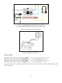
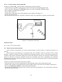
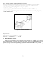
- connect meter of the short circuit loop impedance in accordance with Figure 14,
- perform the measurement,
- the measurement may provoke activation of the RCD switch (it is impossible to perform a measurement).
PE
Figure 14. Connection of the meter.
Expected results:
RE = 6,8 Ω + ZL-N of the network
4.4. Earth resistivity measurements.
Earth resistivity measurements are used to prepare designs of earth systems, in cathode protection or in
geology.
Earth resistivity measurements are performed using four electrodes which are placed in line in equal
distances (Wenner’s method). In order to determine the ground resistivity value it is necessary to measure the
resistance and perform calculations taking into account the distances between the electrodes. Modern meters
permit to take into account the distances between the electrodes and all the calculations are performed
automatically. The meter will display both the resistance value of the measurement probes (in Ω) and the ground
resistivity value (in Ωm).
In order to perform the measurement proceed as follows :
- disconnect the 230 VAC power supply network cable from the socket of the demonstration board,
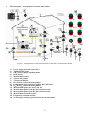
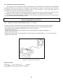
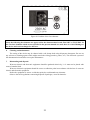
- connect earth resistance and ground resistivity meter (MRU-XXX) to the sockets in accordance with Figure 5,
- place the „ground type selection” switch at the selected position,
- perform the measurement having previously entered to the meter the appropriate value of the distances between
the measurement electrodes.
17