1
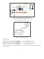
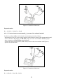
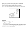
Figure 15. Connection of the meter.
Expected results:
Switch in the position 5 m : ρ = 31 Ωm
Switch in the position 10 m : ρ = 295 Ωm
Switch in the position 20 m : ρ = 5,9 kΩm
4.5. Measurements of the continuity of equipotential bondings.
Using the demonstration board it is possible to simulate a measurement of the resistance the equipotential
bonding of an electric installation. The measurement may be performed between point P1 of the equipotential
bonding and point P2 or P3. It is also possible to simulate irregularities related to the resistance of the
equipotential bonding of point P2 and point P1.
In order to activate this function the RE switch simulating the irregularity must be placed in the „red”
position.
4.5.1. Measurement of the resistance of the equipotential bonding between P1 and P2.
In order to perform a measurement of the resistance of equipotential bonding between P1 and P2 proceed
as follows:
- disconnect the 230 VAC power supply network cable from the socket of the demonstration board,
- place all the switches simulating irregularities in the „green” position,
- turn the RCD switch off,
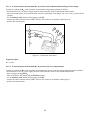
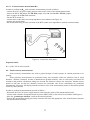
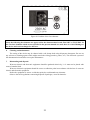
- connect the meter with cables to the network socket of the board in accordance with Figure 16,
- perform the measurement,
- change the position of the irregularities switch RE to the „red” position,
- perform the measurement.
18