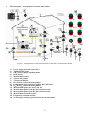
1
4.
Measurements.
4.1.
Measurement of the short circuit loop impedance.
A reliable and the most commonly used method of protection from electric shock consists in protection
from indirect touch in circuits equipped with circuit breakers. The method consists in a automatic disconnection
in the case of fault.
Conductive elements of the device are connected to the protective conductor of the power supply network.
At the moment a hazardous touch voltage appears, which is caused by a metallic short circuit with the phase
conductor of the power supply network, the current will flow in the phase – protective conductor circuit. The
current is called short-circuit current. The passage of the short circuit current will cause activation of the circuit
breakers and the power supply system will be turned off. The condition that must be met to have the protection
level specified for the device as sufficient approved is that the elements must not be under a dangerous touch
voltage for an excessive period of time. Therefore the safety device must respond quickly, and within the period
of time specified in the relevant norms. The condition of appropriate protection may be expressed by the
following equation:
Z
S
≤
U
I
O
A
ZS - short circuit loop impedance.
IA – current activating the circuit breaker within the required period of time.
UO – power supply network nominal voltage in relation to earth.
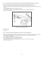
4.1.1. Measurement of the short circuit loop impedance in the L-PE circuit.
Measurement of the short circuit loop impedance in the L-PE circuit may be performed using the MPI5XX meter in the ZL-PE[RCD] function. Should another meter or function be used, the RCD switch of the
demonstration board may be trigged.
In order to perform the measurement proceed as follows:
- connect the 230 VAC power supply network cable to the socket of the demonstration board,
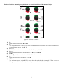
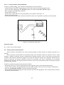
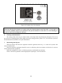
- select the kind of TT or TN network using a jumper in the appropriate position (Figure 3),
- all the switches simulating irregularities must be in the „green” position,
- turn the RCD switch on,
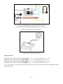
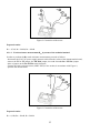
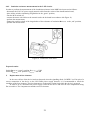
- connect the meter to the power network socket of the board using leads, in accordance with Figure 4,
- perform the measurement.
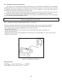
The demonstration board permits to perform measurements of a short circuit loop, whose value may be
artificially overstated (simulation of irregularities). In order to do so, before you proceed to perform the
measurement place the ZL switch in the „red” position. Having finished the measurement, place the ZL switch again
in the „green” position.
7