1
4.6.2. Insulation resistance measurements in the L-PE circuits.
In order to perform the measurement of the insulation resistance in the L-PE circuit proceed as follows:
- disconnect the 230 VAC power supply network cable from the socket of the demonstration board,
- place all the switches simulating irregularities in the „green” position,
- turn the RCD switch off,
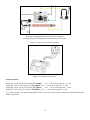
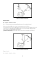
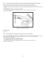
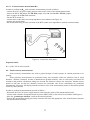
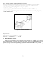
- connect the meter with cables to the network socket in the board in accordance with Figure 19,
- perform the measurement,
- change the position switch of the irregularities of the resistance of insulation RISO(L-PE) to the „red” position,
- perform the measurement.
Figure 19. Connection of the meter.
Expected results:
Switch RISO(L-PE) “green” position: RISO(L-PE) ≥ 3 GΩ
Switch RISO(L-PE) “red” position: RISO(L-PE) = 200 kΩ
5.
Replacement of fuse elements.
In the case a defect of the device has been detected, when the signalling diode „POWER” is off in spite of a
correct connection of the device to the 230V/50Hz power supply network, it is recommended to check the
condition of the fuse elements. The fuse elements are in the mains socket from which the device is powered.
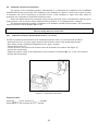
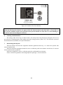
In order to do so, disconnect the power supply cord from the device and raise the fuse compartment using
flat screwdriver. The compartment contains two fuse elements.
21