1
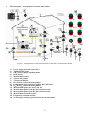
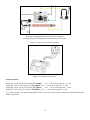
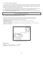
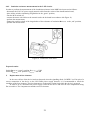
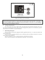
Position of switches simulating irregularities in the electric installation of the measured object.
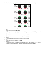
Figure 2. Positions of switches.
1)
2)
3)
4)
5)
6)
7)
RE
High earth resistance at P2. RE = 1kΩ
UB
The acceptable voltage value UB has been exceeded during measurements of the RCD parameters in
the measurement socket. UB > 25 V
RISO(L-PE)
Low insulation resistance – measurement L-PE. RISO(L-PE) = 200 kΩ
RISO(L-N)
Low insulation resistance – measurement L-N. RISO(L-N) = 100 kΩ
RCD-TA
The acceptable disconnection time of the RCD has been exceeded.
ZL
High short circuit loop impedance. ZL ≈ 6 Ω
RCD-IA
The activation current of the RCD is lower than the required value (damaged RCD or excessive
leakage current of the installation). The leakage current of the installation IA ≈ 15 mA
6