1
3.
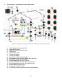
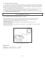
The front panel – arrangement of sockets and switches.
Figure 1. Arrangements of the panel elements of the DB-1 demonstration board.
1)
2)
3)
4)
5)
6)
7)
8)
9)
10)
11)
12)
13)
14)
15)
16)
Power supply network socket 230 V
Additional PE socket
230 V power supply signalling diode
RCD switch
Measurement socket
TN network jumper
TT network jumper
RE1 (ZW RE1) earth electrode jumper
Equipotential pipe connection jumper H2O (ZW H2O)
RE2 (ZW RE2) earth electrode jumper
Measurement points P1, P2, P3, P4, P5
Measurement point of the RE1 (E1) earth electrode
Measurement point of the RE2 (E2) earth electrode
Measurement electrode sockets
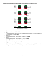
Irregularity selection switches
Ground type switch for ground resistivity measurements
5