1
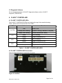
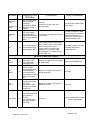
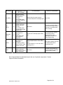
Tables 2 and 3 detail the CLASS™ CONTROLLER connector functions and pin
definitions.
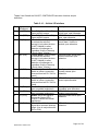
Table 2: J1 – Vehicle I/O Interface
Pin
1
Signal
(WireName)
IN1 (DFO)
2
/IN1 (/DFO )
3
IN2 (DAI)
4
/IN2 (/DAI)
5
IN3 (DNC)
6
/IN3 (/DNC)
7
IN4 (ENA)
8
/IN4 (/ENA)
9
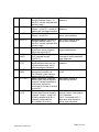
/O1 (/STA)
10
/O2 (/DAO)
MRN 03002-8 TB08-03-192
Function
Description
Door Fully Open: From Fully
Open switch or sensor.
Door Fully Open: From Fully
Open switch or sensor.
“Drunk Alarm”: May be used
to activate the selected
sensor(s) (only when the door
is NOT enabled) to allow
detection of passengers in
immediate vicinity of doorway
(“Drunk Alarm” function).
“Drunk Alarm”: May be used
to activate the selected
sensor(s) (only when the door
is NOT enabled) to allow
detection of passengers in
immediate vicinity of doorway
(“Drunk Alarm” function).
Door Nearly Closed: From 5°
switch or sensor (connection
removed from bus PLC if K2 is
used.)
Door Nearly Closed: From 5°
switch or sensor (connection
removed from bus PLC if K2 is
used).
Enable: From bus PLC when
door is enabled (authorized).
Enable: From bus PLC when
door is enabled (authorized).
Status: Active-low signal to
turn on the Status LED if
CLASS™ detects an internal
malfunction.
“Drunk Alarm”: Active-low
signal when a sensor detects a
target. (Use in conjunction with
DAI or /DAI).
Bus System Voltage when door
is fully open, open otherwise.
GROUND when door is fully
open, open otherwise.
Bus System Voltage when
“drunk alarm” function is
desired, open otherwise.
GROUND when “drunk alarm”
function is desired, open
otherwise.
Bus System Voltage when door
is nearly closed, open
otherwise.
GROUND when door is nearly
closed, open otherwise.
Bus System Voltage when door
is enabled, open otherwise.
GROUND when door is
enabled, open otherwise.
GROUND when active; open
otherwise.
GROUND when active; open
otherwise.
Page 14 of 34