1
Released: May 15, 2003
Revised: August 9, 2006
CLASS™
INSTALLATION and SETUP
USER MANUAL
MRN 03002-8 TB08-03-192
Page 1 of 34
NOTICE
All equipment, systems and/or devices supplied and described in this manual remain the
property of Vapor Bus International, Buffalo Grove, IL, and may be totally or in part a
patented combination.
Illustrations, specifications, and engineering data submitted herein remain the property
of Vapor Bus International and shall not be divulged to others or reproduced or altered
or used in whole or in part as the basis for manufacture without express consent of
Vapor Bus International.
No part of this manual may be reprinted, reproduced, or utilized in any form by
electronic, mechanical or other means now known or hereafter invented, including
photocopying, nor used in any information storage and retrieval system without written
permission of Vapor Bus International.
This manual is furnished for the express purpose of servicing systems and components
supplied by Vapor Bus International.
U.S. and foreign Patents are applicable and/or pending to products described and
illustrated herein. Vapor Bus International reserves the right to discontinue products or
change product specifications at any time without notification.
MRN 03002-8 TB08-03-192
Page 2 of 34
TABLE OF CONTENTS
1.
Definitions
2.
System Overview
3.
Description of Operation
4.
Electronic Control Unit
5.
Installation
6.
Setup
7.
Basic Operation and Troubleshooting
8.
Acceptance
9.
Specifications
Referenced Documents:
CLASS™ Theory Of Operation:
TB08-05-096
CLASS™ Diagnostic Software:
TB08-05-097
CLASS™ Specifications and I/O:
TB08-04-019
MRN 03002-8 TB08-03-192
Page 3 of 34
1. Definitions
AUTHORIZE: Authorizing the door is done by the Controlling PLC activating the
Enable input on CLASS™.
BIT: Built in Tests: Self Tests that CLASS™ runs on power-up.
CLASS™: Contact-Less Acoustic Sensing System.
DEAD ZONE: Any region in which an object is not detectable (and therefore
cannot become a Target). There are typically four regions in which dead
zones occur:
i. Within a short distance from the face of the sensor
(typically 10-12 inches)
ii. Within a tolerance band around any existing Target
iii. Outside the sensing range of the sensor
iv. Regions ignored under program control (example: see MSU Limit)
DE-AUTHORIZE: De-authorizing the door is done by the Controlling PLC
releasing the CLASS™ Enable input.
DFO: Door Fully Open (normally an 85º switch or proximity sensor)
DOU: Door Operator Unit – the device that opens the door
DNC: Door Nearly Closed (normally a 5° switch or proximity sensor)
DOR: Door Open Request – CLASS™ output to bus PLC
LPS, RPS, MSU: Left Panel Sensor, Right Panel Sensor, Middle Sensor Unit
(Center Sensor)
PLC: The onboard bus computer that issues commands to CLASS™
TARGET: An object detected by CLASS™’s sensing system.
Fixed Target: a Target that is part of CLASS™’s “fixed” environment, i.e.,
always present. Fixed Targets may be permanently programmed by the
installer or may be automatically determined by CLASS™ at turn-on
Acquired Target: a Target that is not “fixed”; typically a passenger.
MRN 03002-8 TB08-03-192
Page 4 of 34
2. System Overview
Vapor’s Contact-Less Acoustic Sensing System - “CLASS™” - is designed to operate
in public transportation environments, principally buses. It combines acoustic technology
with signal processing techniques to enable passengers to initiate door opening and exit
a vehicle without physical contact with the doors.
The CLASS™ system consists of three ultrasonic sensors and a signal processing and
control unit (CLASS™ CONTROLLER). When activated, the sensors emit bursts of
ultrasonic pulses to survey specific spaces within the doorway. The echoes received by
the sensors are analyzed by the CLASS™ CONTROLLER to determine whether or not
an object (typically a person) is present. When an object is detected, the CLASS™
CONTROLLER signals the door controls, which initiate the appropriate response.
CLASS™ can provide different functionality during each phase of door operation:
• When a door is enabled but still closed, CLASS™ can emulate a touch bar or
touch tape for passenger actuation
• While a stream of passengers is exiting, CLASS™ can provide a “hold open”
function
• While the doors are closing, CLASS™ can enhance the sensitive edge function
2.1 CLASS™ system components include the following:
• CLASS™ CONTROLLER
•
Left Panel Sensor (LPS)
•
Middle Sensor Unit (MSU)
•
Right Panel Sensor (RPS)
The panel sensors (LPS, RPS) are directly mounted on each door panel. These sensors
have a relatively narrow beam angle (approximately 6-9 degrees) and operate at a
frequency of 150-170 KHz. Their functions are (1) to initiate door opening and (2)
enhance the sensitive edge while closing. The center sensor (MSU) is typically located
on the door header, approximately at the center of the doors. Its function is to monitor
the door pathway while the doors are open to prevent premature closing. It has a wider
beam angle (approximately 12 degrees) and operates at a frequency of 120 KHz.
When the sensors sense the presence of a passenger in the defined zones, and the
door is authorized to open, the CLASS™ CONTROLLER sends a “Door Open Request”
(DOR) signal to the Door Operator Unit (DOU). Once the passenger or passengers exit
the doorway and the exit area is clear, the DOR signal is removed and the door is
allowed to close.
MRN 03002-8 TB08-03-192
Page 5 of 34
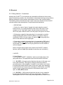
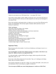
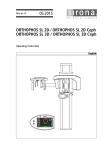
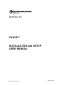
The chart below shows the typical "Beam Width" (or cone diameter) vs. distance for
CLASS™ transducers. Note that the Beam Width is approximate, that is, it is defined as
point at which the sensitivity is one-half the on-axis value. So it is not a situation where
an echo will be received in the beam but not outside it; instead, the echo amplitude will
be more and more reduced as the distance from the center axis increases until it
reaches a point where it is below threshold. The "effective" beam width depends on the
strength of the transducer and the threshold value set in the CLASS™ parameters.
CLASS Beam Width vs Distance
(Panel=6-9º, Middle=12º)
20
18
Panel Sensor
6 deg
Width (inches)
16
14
Middle
Sensor
12
10
Panel Sensor
9 deg
8
6
4
2
0
8
20
32
44
56
68
80
Distance (inches)
MRN 03002-8 TB08-03-192
Page 6 of 34
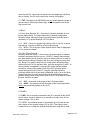
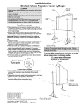
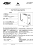
2.2 Door Movement
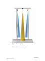
Figure 1 shows the basic movement pattern of the doors and indicates the sensors’
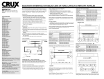
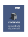
zones. Figures 2, 3, and 4 show three-dimensional graphical depictions of the sensing
zones in both door-closed and door-open positions.
Sensing zone (Panel Sensor)
Doors
Fully
Open
Panel Sensor (mounted on top edge of panel)
Door panel
Left
Doors
Closed
Right
Middle Sensor
(ceiling mounted)
Sensing zone (Middle
Sensor
Top View, Vehicle Interior
Figure 1: Sensors and Sensing Zones
MRN 03002-8 TB08-03-192
Page 7 of 34
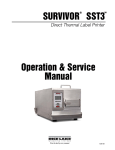
Figure 2: Doors Closed and Enabled
(Shading indicates active sensing regions)
MRN 03002-8 TB08-03-192
Page 8 of 34
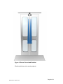
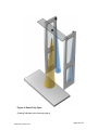
Figure 3: Doors Fully Open
(Shading indicates active sensing regions)
MRN 03002-8 TB08-03-192
Page 9 of 34
Figure 4: Doors Fully Open
(Shading indicates active sensing regions)
MRN 03002-8 TB08-03-192
Page 10 of 34
3. Description of Operation
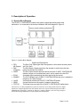
3.1 System Block Diagram
The CLASS™ CONTROLLER contains the system’s signal-processing and control
electronics. It is connected to the bus as indicated in the block diagram in Figure 5.
Figure 5: Interface Block Diagram
• DFO
(85 Degree)
• DNC
(5 Degree)
• OPEN
• ECHO
• ENABLE
• On/Off
• SEND
• STATUS
Signals and Descriptions
The Door Fully Open signal from the operator is active when the door panels
are Fully Open.
The Door Nearly Closed signal from the operator is active when the door
panels are almost Fully Closed.*
The Door Open Request becomes active when the CLASS™ CONTROLLER
detects a target on an enabled door panel, and is routed to the bus PLC.
An analog signal representing the echo received by the sensor.
The PLC indicates to the CLASS™ CONTROLLER that the door is enabled to
respond to an Open Request.
A switch that controls the CLASS™ CONTROLLER power.
A signal that turns on the sensor’s ultrasonic pulse burst.
This signal turns on a light if the CLASS™ CONTROLLER malfunctions.
*Since the PLC is often programmed to ignore the touch bars once closing doors past the 5 degree
position, the 5 degree signal from the door operator to the PLC may be rerouted through the CLASS™
CONTROLLER, allowing the controller to delay the 5 degree indication to the PLC long enough to
ensure that if a target is detected, a re-open request can be acted upon.
MRN 03002-8 TB08-03-192
Page 11 of 34
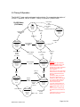
3.2 Theory Of Operation
The CLASS™ state machine diagram is shown below. For a complete description of
CLASS™ operation, refer to CLASS™ Theory of Operation (TB08-05-096)
CLASS States
(PLC Mode)
Drunk Alarm
input
is ACTIVE
Idle
Drunk Alarm
input
is INACTIVE
Panel=OFF
Middle=OFF
K1=OFF
K2=OFF
Drunk Alarm
ENABLE
is
OFF
Timer2 Elapsed
& ENABLE is
OFF
Panel=OFF
Middle=ON
K1=OFF
K2=OFF
ENABLE is
ON
Timer2 Active
Touch To Open
Timer2 Elapsed
& ENABLE is
ON
Panel=ON
Middle=Reduced5
K1=OFF
K2=ON
Panel & Middle
are Not
Sensed
& 5° is ON
Panel=Reduced4
Middle=OFF
K1=OFF
K2=OFF
Panel is Sensed
or
5° is OFF
Panel or Middle
is Sensed
Door Is Closing
Door Is Opening
Panel or Middle
is Sensed
Panel=ON
Middle=Reduced4
K1=OFF
K2=ON
Panel=ON
Middle=OFF
K1=ON1
K2=OFF
Panel or
Middle
is Sensed
85° is
OFF
85° is
ON
Wait for Close
Panel or
Middle
is Sensed
Panel=ON
Middle=ON
K1=OFF
K2=ON
Timer1 Elapsed
Door Fully Open
Panel or
Middle
is Sensed
Panel=ON
Middle=ON
K1=ON1
K2=OFF
Timer1 Active
Panel=ON
Middle=ON
K1=ON1
K2=OFF
MRN 03002-8 TB08-03-192
ENABLE is
ON
Panel & Middle
are Not
Sensed
5° is ON &
Time>2
Sec
Remarks:
1. The K1(Door Open Request)
Relay is energized as long as an
object is detected. K1 will deenergize after no object is detected
for Timer 4 seconds or when
Timer1 elapses.
Note when K1 is active, Outputs #4
and #5 are active. If the door is REopening, Outputs #3 and #6 are
also active.
2.The K2 (5°) Relay is energized
when Timer1 elapses and is
released only after Timer2 elapses.
3. In "Touch To Open" state, the
panel sensors scan only up to
110cm from the sensor.
4. In "Door Is Closing" state, the
middle sensor scans only up to a
programmable distance from the
sensor.
5. The activation of sensors may
be different if the Snow Mode is in
use.
6. Each sensor has a 12" (approx)
dead-zone at its surface.
Page 12 of 34
3.3 Diagnostic Software
For a complete description of CLASS™ diagnostic software, refer to CLASS™
Diagnostic (TB08-05-097).
4. CLASS™ CONTROLLER
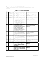
4.1 CLASS™ CONTROLLER LEDs
The CLASS™ CONTROLLER LEDs are located on the top of the controller housing.
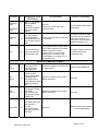
Table 1 defines the color and function of the LED’s.
LED
Color
Red
SYSTEM
Function
Power is ON
Orange (Slow Flashing)
System is running (Calibration is complete)
Orange (Fast Flashing)
Problem detected (BIT failure)
LPS
MSU
RPS
Green
LPS is Sending
Orange
Target is detected by LPS
Green
MSU is Sending
Orange
Target is detected by MSU
Green
RPS is Sending
Orange
Target is detected by RPS
Table 1 – CLASS™ CONTROLLER LEDS
4.2 CLASS™ CONTROLLER Connectors
Figure 6 shows the location of connectors J1 and J2
Figure 6: Interface
MRN 03002-8 TB08-03-192
Page 13 of 34
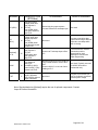
Tables 2 and 3 detail the CLASS™ CONTROLLER connector functions and pin
definitions.
Table 2: J1 – Vehicle I/O Interface
Pin
1
Signal
(WireName)
IN1 (DFO)
2
/IN1 (/DFO )
3
IN2 (DAI)
4
/IN2 (/DAI)
5
IN3 (DNC)
6
/IN3 (/DNC)
7
IN4 (ENA)
8
/IN4 (/ENA)
9
/O1 (/STA)
10
/O2 (/DAO)
MRN 03002-8 TB08-03-192
Function
Description
Door Fully Open: From Fully
Open switch or sensor.
Door Fully Open: From Fully
Open switch or sensor.
“Drunk Alarm”: May be used
to activate the selected
sensor(s) (only when the door
is NOT enabled) to allow
detection of passengers in
immediate vicinity of doorway
(“Drunk Alarm” function).
“Drunk Alarm”: May be used
to activate the selected
sensor(s) (only when the door
is NOT enabled) to allow
detection of passengers in
immediate vicinity of doorway
(“Drunk Alarm” function).
Door Nearly Closed: From 5°
switch or sensor (connection
removed from bus PLC if K2 is
used.)
Door Nearly Closed: From 5°
switch or sensor (connection
removed from bus PLC if K2 is
used).
Enable: From bus PLC when
door is enabled (authorized).
Enable: From bus PLC when
door is enabled (authorized).
Status: Active-low signal to
turn on the Status LED if
CLASS™ detects an internal
malfunction.
“Drunk Alarm”: Active-low
signal when a sensor detects a
target. (Use in conjunction with
DAI or /DAI).
Bus System Voltage when door
is fully open, open otherwise.
GROUND when door is fully
open, open otherwise.
Bus System Voltage when
“drunk alarm” function is
desired, open otherwise.
GROUND when “drunk alarm”
function is desired, open
otherwise.
Bus System Voltage when door
is nearly closed, open
otherwise.
GROUND when door is nearly
closed, open otherwise.
Bus System Voltage when door
is enabled, open otherwise.
GROUND when door is
enabled, open otherwise.
GROUND when active; open
otherwise.
GROUND when active; open
otherwise.
Page 14 of 34
11
/O3 (/RCY)
12
/O4 (/OPN)
13
O5 (OPN)
14
O6 (RCY)
15
K2-C (K2C)
16
K2-N.C.
(K2NC)
17
/TARGET
(/TGT)
18
POWER
(PWR)
19
K1-C (K1C)
20
K1-OUT
(K1-O)
MRN 03002-8 TB08-03-192
Recycle Request: Obstruction
Recycle Request Output – to
bus PLC, usually in parallel with
sensitive edge
Open: Door Open Request
Output – to bus PLC, usually in
parallel with touchtape/touchbar
Open: Door Open Request
Output – to bus PLC.
GROUND when active; open
otherwise.
Recycle Request: Obstruction
Recycle Request Output – to
bus PLC, usually in parallel with
sensitive edge.
5° degree Override In: 5°
signal from source (originally
connected to bus PLC)
5° Override Out: 5° signal to
PLC (rerouted through
CLASS™)
/Target: Provides an active low
signal sufficient to drive a lowcurrent indicator light. Active
while any target is detected.
Power: Connect to power
source near controller via
On/Off switch (when optional
power relay K3 is not used.)
Open: Used when a normally
closed Open Request signal is
required. Usually connected to
local power, but can be
connected to Ground if required
by bus PLC
Open: Used when a normally
closed Open Request signal is
required. Output – to bus PLC
(Polarity determined by K1-C;
internally configurable as
N.C.(default) or as N.O.)
Bus System Voltage when
active, open otherwise.
GROUND when active; open
otherwise.
Bus System Voltage when
active, open otherwise.
Same as active contact of 5
degree switch/sensor.
Connected to K2-C when door
is allowed to be de-authorized,
open otherwise.
GROUND when active; open
otherwise
Bus System Voltage when bus
is ON.
Bus System Voltage or
GROUND as required.
If N.C.: Open when door open
request is active, connected to
K1-C otherwise.
If N.O.: Connected to K1-C
when door open request is
active, Open otherwise.
Page 15 of 34
21
22
23
24
Local 12/24
(SWPW)
[optional
components
required]
On/Off 12
(ON12)
[optional
components
required]
On/Off 24
(ON24)
[optional
components
required]
GND (GND)
Optional: used only when
optional power relay K3 is used.
Connect to power source near
controller
Bus System Voltage when bus
is ON.
Optional: used only when
optional power relay K3 is used.
From On/Off switch connected
to 12V nominal power
+12V when CLASS™ is to be
ON, Open otherwise.
Optional: used only when
optional power relay K3 is used.
From On/Off switch connected
to 24V nominal power
+24V when CLASS™ is to be
ON, Open otherwise.
Return for Power
GROUND
Table 3: J2 – Diagnostic and Programming
Pin
2
3
5
4
Signal
RCV
XMIT
GND
/PSEN
Description
Data from CLASS™ to Diagnostic Computer
Data from Diagnostic Computer to CLASS™
Ground
Used to set controller firmware program mode. See CLASS
Diagnostic (TB08-05-097)
Figure 7 shows the location of the J3, J4, J5, and J6 connectors
Figure 7: Connectors J3 – J6
MRN 03002-8 TB08-03-192
Page 16 of 34
Table 4: J6 – LPS, J4 – RPS
Pin
1
2
3
4
5
6
Signal
Power
SEND
GND
ECHO
Shield
-
Description
Provided by CLASS™ CONTROLLER
Controlled by CLASS™ CONTROLLER
Provided by CLASS™ CONTROLLER
Returned to CLASS™ CONTROLLER
Grounded at CLASS™ CONTROLLER
No Connection
Table 5: J5 - MSU
Pin
1
2
3
4
5
6
Signal
Shield
ECHO
GND
SEND
Power
Description
No Connection
Grounded at CLASS™ CONTROLLER
Returned to CLASS™ CONTROLLER
Provided by CLASS™ CONTROLLER
Controlled by CLASS™ CONTROLLER
Provided by CLASS™ CONTROLLER
Table 6: J3 – Test
Pin
1
2
3
4
5
6
7
8
MRN 03002-8 TB08-03-192
Signal
SEND
LPS Echo
MSU Echo
SEND
SEND
RPS Echo
Gnd
Gnd
Description
Use as scope trigger (identical to 4 & 5)
Use to measure LPS echo
Use to measure MSU echo
Use as scope trigger
Use as scope trigger
Use to measure RPS echo
Scope probe ground
Scope probe ground
Page 17 of 34
5.0 Installation
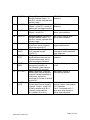
5.1 Mechanical
5.1.1 Sensor Alignment - Panel Sensors
The panel sensors have two functions: open the door, and protect the door’s edge. So
their positions should be as close as possible to the door edge without intruding into the
non-metal zone. The sensor has about 12 inches of dead zone from its surface and the
beam fan is a 3D cone; aligning the cone axis straight down (as shown below) allows
sensing both the edge and the “touch-to-open” zone.
Bus
Figure 8: Panel Sensor Alignment
MRN 03002-8 TB08-03-192
Page 18 of 34
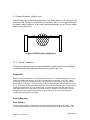
5.1.2 Sensor Alignment - Middle Sensor
Figure 9 shows the recommended alignment of the Middle Sensor on the bus floor with
the door closed. The top of the drawing is the outside of the bus. It is suggested to point
the beam slightly outside so it will protect exiting passengers but will not see farther
objects (trees, poles, etc.).
Door
Door
Figure 9: Middle Sensor Alignment
5.1.3 “Typical” Installation
The following instructions are for a typical installation. Specific details may be different
for different buses; they depend on the type of bus, type of door, etc.
Preparation
Remove the Grab Handles and Touch Tape from the rear doors. Flange-locking bolts (5/16-18)
attach the handles and require a 9/16” box or socket wrench for removal. The Touch Tape is
secured by 4 small cross recessed screws, 2 at the top and 2 at the bottom, that are removed
with a Phillips screw driver. The tape is also held by an aluminum track that the tape can be slid
out of. Once the tape has been removed from the track, the attaching pop rivets can be removed
by drilling through with a 1/8” inch diameter drill. Cut the wire of the touch tape, tape the live
ends and remove to the connection point above the doors. Because of the routing of the wire
along the path of the sensitive edge tubing, it may be best to cut the wire in the roller area
accessed by removing the cover plate.
Sensor Mounting
Door Sensors
The door sensors should be attached to the upper leading (inboard) edge of the doors. There
should be approximately ¼ inch from the top of the door to the top of the sensor bracket. The
MRN 03002-8 TB08-03-192
Page 19 of 34
bottom of both sensors should be the same distance from the floor for the installation of the
sensors to several busses. The sensor is held to the bracket by a ¼-20 x .50 flathead screw.
Lead the sensor cable out correct side of the sensor case (toward the bracket mounting holes).
A 5/16” hole must be drilled through the roller bracket to route the sensor cables along with the
sensitive edge tubing to where the controller will be mounted above the door operator. The
sensor mounting brackets are attached to the door by ¼-20 RIVNUTS installed in the aluminum
door extrusion. The brackets have counter-bored slots for side-to-side adjustment and to clear
the flange of the RIVNUTS. Mark the location (centered in the slot width) for drilling the two holes
in the extrusion when the bracket is held in the correct vertical position. The ¼-20 RIVNUTS are
included in the sensor hardware kit with the brackets. Drill a .332/.338” diameter hole (use an
8.5mm (.3346”) or a Q (.3320”) letter drill) for installation. Use a B.F. Goodrich wrench type
header tool number C-845-2520 to set the RIVNUT (available from Liberty Engineering in
Chatsworth, California, phone 818-786-8111).
Attach the assembled sensor and bracket to each door using 2 ea. ¼-20 x .750 pan head screws,
washers and lock washers. Apply 2 layers of heat shrink tubing 2.38” long tight to the sensor.
Route the cable through the hole into the roller bracket and up to the controller area. Loosely tie
(nylon wire tie) the cable to the sensitive edge tubing taking care to not pinch the plastic tubing.
Middle Sensor
The middle sensor is mounted to a bracket installed using Rivnuts into the bottom of the door
operator base plate. Attach the sensor to the bracket using a ¼-20 x .50 pan head screw,
washer and lock washer from the hardware kit. Position the sensor centered in the opening with
the attaching screw to the outboard of the bus. Mark the holes of the bracket for drilling the base
plate. Drill the holes for installing the ¼-20 Rivnuts after assuring that the door operator base
plate is clear. Use the installation tool to attach the 2 Rivnuts. Use the 2 ea. ¼-20 x .75 pan
head screws with lock washers and flat washers to attach the assembled sensor/bracket to the
base plate. Use the existing wire hole or drill a 5/16” diameter hole to route the cable up to the
controller mounting area. Apply 2 layers of heat shrink tubing and route the cable up to the
controller.
Control Box Mounting
The Control Box is mounted to the bus structure above the door operator (inside the Air
Conditioning Duct) via a mounting plate. Locate a section on the bus structure to drill 11/64”
(.1719) diameter holes located from the mounting holes in the mounting plate. Select an area of
the structure that picks up at least 3 of the 4 holes. Use the 10-32 self-tapping screws to mount
the plate to the structure sheet metal. Secure the Control Box to the plate with 10-32 nuts and
washers.
Light and Switch Mounting
The master Switch and Indication Light are mounted to the switch panel above the bus driver’s
seat located behind the cover. Mount the bracket behind the right side of the existing switch
mounting bracket. Align the holes with the other switches if possible. After drilling through both
brackets, attach with 2 ea. #6 or #8 sheet metal screws or pop rivets. The Light and Switch
mounting holes should be aligned horizontally on the right with the attachment screws on the left
side of the bracket. (Due to the geometry available, the mounting flange is not used and will be
sticking towards the front of the bus.)
Mount the Switch in the left hole and the Light in the right hole. The Light has insulated Fast On
spade terminals. The negative Light terminal is the insulated male ¼” Fast On and may need the
MRN 03002-8 TB08-03-192
Page 20 of 34
corners shaved by scraping with a knife blade to be able to fit through the .50” diameter mounting
hole. Once the negative wire is routed through the hole, the positive lead can be threaded
through and the Light can be snapped into the bracket.
Locate 24 V DC positive on terminal #2 of the terminal strip located behind the switches and
connect to the Light positive lead and the common terminal of the Switch using 16 AWG wire.
The terminal strip needs #10 ring tongue terminals, the Light needs an insulated ¼ Fast On male
(to fit into a ¼” fast on female for the positive lead of the Light assembly) and the Switch
connection needs a # 6 ring tongue terminal. On the door side of the bus, locate spare wires
(#12 and #13) that are routed in the wire harness from over the front door to the back door area.
Hook up the Light negative lead terminal to the #13 spare using 16 AWG wire. The negative
terminal end of the Light will needs a ¼ Fast On female (to mate with the ¼” Fast On male of the
Light lead) and the spare wire connection needs a 16AWG butt splice. The Switch needs to be
hooked up to the # 12 spare using 16 AWG wire. The Switch connection terminal end needs a
#6 ring tongue terminal and the spare wire end needs to be butt spliced to the spare wire.
For convenience the Vapor part numbers for the 16 AWG terminals are as follows:
P/N
Description
98010749
Terminal, ¼ Fast On Male, Insulated
98010749-01 Terminal, ¼ Fast On Female
98320180-20 Terminal, # 6 Ring Tongue
98320180-23 Terminal, # 10 Ring Tongue
Handle Installation
Attach the handle to the existing upper 5/16-18 RIVNUT (on the trailing edge of the door) and
mark the location of the lower hole with the handle vertical. Drill a .413/.423 hole (use a letter Z
(.4130) or a 27/64” (.4219) drill bit) for the RIVNUT. Install the 5/16” RIVNUT from the kit using a
B.F. Goodrich wrench type header tool number C-722-3118.
Finishing
Patch the small rivet and screw holes in the door (from the touch strip mounting) and put in a
flush plug in the wire hole after sizing the hole for the plug. Sand and repaint the repaired area
with a semi-gloss black. Attach supplied labels (if appropriate) to the doors.
MRN 03002-8 TB08-03-192
Page 21 of 34
5.2 Electrical
5.2.1 Wiring Harness - Connections
Although the CLASS™ I/O requirements are well-defined, differences in bus wiring,
types of controllers, polarities, etc. all contribute to the fact that each type of bus must be
carefully assessed to ensure that the requirements of the I/O are correctly fulfilled.
The following section describes the input, output, and power interface for the CLASS™
controller and provides a description of requirements and alternatives.
1. DEFINITIONS
1.1 Active: the “active” state of a signal is the state when the event of
interest occurs. It is usually described by the name of the signal. As an
example, for the “Fully Open” signal, the active state occurs when the
door is fully open. When the door is not fully open, the signal is not active.
1.2 High-going: a signal is high-going when it is connected to a positive
voltage (usually 24V) when it is active. (When it is not active it may be
connected to GND or it may be open.) A signal which is high-going when
active is also called an active-high signal.
1.3 Low-going: a signal is low-going when it is connected to GND when it
is active. (When it is not active it may be connected to a high voltage or it
may be open.) A signal which is low-going when active is also called an
active-low signal.
Notes: All signal names below are as used on the CLASS™ interface
harness, and are in bold. [Non-standard connections are in brackets.]
2. INPUTS
2.1 Input Signals
For the standard CLASS™ installation, inputs may be high-going or lowgoing when active. The appropriate input must be used for each case.
2.1.1. IN1 (DFO) - this input must be high when the door is fully open, and
low or open otherwise. This signal is usually provided by a switch or
proximity sensor on the baseplate. If a switch is used, make sure it closes
to system high voltage when the door is fully open, and is open otherwise.
If a proximity sensor is used, make sure that it is a PNP sensor. If an NPN
sensor is used, or the switch connects to GND when the door is fully
open, use /IN1 (/DFO) instead.
2.1.2. IN2 (DAI) – If IN2 becomes high when the door is not in operation,
the sensor(s) will be turned on for use as a “drunk alarm”. This input is
used together with OUT2, which will provide target detection status for the
MRN 03002-8 TB08-03-192
Page 22 of 34
drunk alarm and is intended for use by the bus PLC. If a low-going
command is preferred, use /IN2 (/DAI) instead.
2.1.3. IN3 (DNC) - this input must be high when the door is fully closed,
and low or open otherwise. This signal is usually provided by a switch or
proximity sensor on the baseplate. If a switch is used, make sure it closes
to a system high voltage when the door is fully closed, and is open
otherwise. If a proximity sensor is used, make sure that it is a PNP
sensor. If an NPN sensor is used, or the switch connects to GND when
the door is fully open, use /IN3 (/DNC) instead. Note that not all buses
have a 5° switch or sensor. For these buses a 5° switch is a required
installation item.
2.1.4. IN4 (ENA) – this input must be high when the door is unlocked
and/or enabled to be opened. When this input goes high, CLASS™ turns
on its panel sensors and begins looking for targets. It is usually supplied
from the positive side of the Green Light. If a low-going signal is all that is
available, use /IN4 (/ENA) instead.
3. OUTPUTS
CLASS™ has both low-going and high-going outputs, depending on
function. Both output types are open when not active.
3.1. /O1 (/STA) – this must be connected to the status light. If a spare
wire is available, it may be used; if not, wires are added. The other side of
the status light is connected to bus voltage (12V or 24V).
3.2. /O2 (/DAO) – this signal will be low when any sensor detects a valid
target in Drunk Alarm mode. It is for use by the bus PLC with IN2
3.3. /O3 (/RCY) – this signal will be low when CLASS™ is requesting the
PLC to re-open the door (similar to a sensitive edge). This output is used
when the bus PLC logic does not respond to a touchtape input while the
door is closing. See O6 for the active-high version of this signal.
3.4. /O4 (/OPN) - this signal will be low when CLASS™ is requesting the
PLC to open the door (similar to a touchtape). See O5 for the active-high
version of this signal.
3.5. O5 (OPN) – this signal will be high when CLASS™ is requesting the
PLC to open the door (similar to a touchtape). If the bus PLC logic
responds to to a touchtape input while the door is closing, it is also used
when CLASS™ is requesting the PLC to re-open the door (similar to a
sensitive edge). If not, O6 must also be used. See /O4 for the active-low
version of this signal.
3.6. O6 (RCY) - this signal will be high when CLASS™ is requesting the
PLC to re-open the door (similar to a sensitive edge). This output is used
MRN 03002-8 TB08-03-192
Page 23 of 34
when the bus PLC logic does not respond to a touchtape input while the
door is closing. See /O3 for the active-low version of this signal.
3.7. /TGT - this signal is at GROUND when any sensor detects a target. It
may be used to control an indicator light, but is not capable of driving a
high-current load.
4. RELAY
4.1. Door Open Request (K1) – this relay is optionally available for nontypical requirements. The output terminal is by default configured as
Normally Closed, although it may be reconfigured as Normally Open if
necessary. K1 is active whenever /OUT4 is active.
4.1.1 K1C – Connect to system high voltage (12V or 24V) for an activehigh request. Connect to GND for an active-low request
4.1.2 K1-O – This is the Door Open request output. Refer to paragraph
4.1 for connection details.
4.2. Fully-Closed Override
Normally, when the bus PLC receives the fully-closed signal, it releases
interlocks and allows the bus to move. CLASS™ needs to have enough
time after the door is fully closed, but prior to allowing the bus to move, to
make sure that nothing is caught in the door (such as a purse strap, belt,
etc). Relay K2 is used to delay the fully-closed switch information from
reaching the bus PLC for that short time, just long enough for CLASS™ to
ensure nothing is entrapped. Connecting K2 means that the original
connection from the fully-closed switch to the PLC is broken and rerouted through K2 in the CLASS™ controller. Note that while this
technique works well on a door with a differential engine, for an Air-Open
Spring-Close door, the lock pawl will fall into the mechanically-locked
position once the door is fully closed, and CLASS™ is not able to re-open
the door, so K2 is not used.
4.2.1 K2C – connected to the output of the fully closed switch
4.2.2 K2NC – connected to where the output of the fully-closed switch
used to be connected (typically to bus PLC).
5. POWER
5.1. PWR – this is normally connected to the N.O. terminal of the On/Off
switch, whose Common terminal is connected to a local source of bus
system voltage (12V or 24V).
5.2. SWPW - this switched power is connected to a local (near the rear
door) source of bus system voltage (12V or 24V). This signal is used
instead of Pwr (5.1) when the optional internal power relay (K3) is used.
MRN 03002-8 TB08-03-192
Page 24 of 34
5.2. GND – this is permanently connected to bus ground.
5.3. On12 – When the optional internal power relay is used on a 12 Volt
vehicle, it is controlled by this signal coming from the N.O. terminal of the
On/Off switch. If On12 is used, PWR (5.1) is not used; SWPW (5.2) is
used instead. The On/Off switch Common terminal is connected to bus
system voltage (12V) via a wire from the same source as used for
paragraph 5.2
5.4. On24 – this is used similarly as On12, but for a 24V vehicle.
The following table lists “standard” connections and alternatives for “non-standard”
connections
MRN 03002-8 TB08-03-192
Page 25 of 34
CLASS™ – Harness Connections for “Standard” and
“Non-Standard” Bus
SIGNAL J1
DESCRIPTION
(STD Bus)
STANDARD
NON-STANDARD
POWER
PWR
18
+11 to +29 VDC when
CLASS™ is to be ON;
0 VDC when Bus is
OFF
GND
24
Vehicle Ground
Connect to Bus Ground at rear door
Connect to Bus Ground at
rear door
21
Local (rear door)
source of power when
optional power relay is
used
Not Used
+11 to +29 VDC when
CLASS™ is to be ON; 0
VDC when Bus is OFF
[Optional]
On12
22
On/Off control when
optional power relay is
used – 12V vehicle
Not Used
[Optional]
On24
23
On/Off control when
optional power relay is
used – 24V vehicle
Not Used
[Optional]
SWPW
Connect to N.O. Contact of On/Off
Switch (COM Contact of On/Off
Switch connected to bus system
voltage)
Use Local 12/24 and On/Off
12 or On/Off 24.
Connect to N.O. Contact of
On/Off Switch (COM Contact
of On/Off Switch connected to
Bus +12V)
Connect to N.O. Contact of
On/Off Switch (COM Contact
of On/Off Switch connected to
Bus +24V)
INPUTS TO CLASS™ (From Bus)
IN1 (DFO)
[Std]
1
/IN1 (/DFO)
[Non-Std]
2
IN2 (DAI)
[Std]
/IN2 (/DAI)
[Non-Std]
3
4
IN3 (DNC)
[Std]
5
/IN3 (/DNC)
[Non-Std]
6
High (+11-29V) when
Door IS Fully Open;
Low (GND or OPEN)
when Door is NOT
Fully Open
High (+11-29V) to
ACTIVATE Middle
Sensor (when door is
NOT enabled);
Low (GND or OPEN)
to DEACTIVATE
Middle Sensor (when
door is NOT enabled)
High (+11-29V) when
door is open LESS
than 5º;
Low (GND or OPEN)
when door is open
GREATER than 5º
MRN 03002-8 TB08-03-192
Use IN1.
Connect to N.O Contact of Fully
Open Switch (COM Contact of Fully
Open Switch connected to +24V) or
to output of Fully Open PNP Prox
Use /IN1.
Connect to N.O Contact of
Fully Open Switch (COM
Contact of Fully Open Switch
connected to GND) or to
output of Fully Open NPN
Prox.
Optional - connect to PLC per Bus
Builder instruction
Use /IN2
Connect to N.O Contact of Fully
Closed Switch (COM Contact of
Fully Closed Switch connected to
+24V) or to output of Fully Closed
PNP Prox
Use /IN3.
Connect to N.O Contact of
Fully Closd Switch (COM
Contact of Fully Closed
Switch connected to GND) or
to output of Fully Closed NPN
Prox.
Page 26 of 34
SIGNAL J1
IN4 (ENA)
[Std]
7
/IN4 (/ENA)
[Std]
8
[Optional]
K1C
K2C
19
15
DESCRIPTION
(STD Bus)
High (+11-29V) when
door IS enabled
(unlocked);
Low (GND or OPEN)
when door is NOT
enabled
High (+11-29V) when
door open request
requires SOURCE;
Low (GND) when door
open request requires
SINK
Same as IN3 (DNC) –
used to interrupt fully
closed signal to bus
STANDARD
NON-STANDARD
Use IN4.
Connect to “Green Light” (nongrounded side)
Use /IN4 when enable signal
is low-going.
Connect to +24V source at rear door
for SOURCE
Connect to Ground for SINK.
For non-PLC bus, connect to
a signal that is active (+1129V) ONLY when the door is
enabled and safe to exit
Disconnect wire from N.O Contact of
Fully Closed Switch or Prox to Bus
PLC (COM Contact of Fully Closed
Switch connected to +24V).
Connect K2C to cut end of wire
leading to N.O Contact of Fully
Closed Switch or to output of Fully
Closed PNP Prox
Not Used (Typically not used
for AOSC doors due to
mechanical lock)
OUTPUTS TO BUS (From CLASS™)
/O1
(/STA)
9
/O2
(DAO)
10
/O3
(/RCY)
11
/O4 (/OPN)
12
High (OPEN) when
status light is OFF;
Low (GND) when
status light is ON
High (OPEN) when
sensors do NOT
detect a target (When
activated by IN2);
Low (GND) when a
sensor detects a target
(When activated by
IN2)
Low (GROUND) when
door re-open request
is ACTIVE;
High (OPEN) when
door re-open request
is INACTIVE
Low (GND) when door
open request is
ACTIVE;
High (OPEN) when
door open request is
INACTIVE
MRN 03002-8 TB08-03-192
Connect to negative (non-24V) side
of Status lamp
Same as STANDARD Bus
Optional - connect to PLC per Bus
Builder instruction
Not Used
Optional - connect to PLC per Bus
Builder instruction
Not Used
Not Used
Active-low door open request
– connect appropriately
Page 27 of 34
SIGNAL J1
O5 (OPN)
O6
(RCY)
14
[Optional]
K1-O
K2NC
/TGT
13
20
16
17
DESCRIPTION
(STD Bus)
High (Bus system
voltage) when door
open request is
ACTIVE;
Low (OPEN) when
door open request is
INACTIVE
High (Bus system
voltage) when door
re-open request is
ACTIVE;
Low (OPEN) when
door re-open request
is INACTIVE
[K1-C] when door
open request is
ACTIVE;
OPEN when door
open request is
INACTIVE
OPEN when CLASS™
Fully Closed is
INACTIVE;
CLOSED (to K2-C)
when CLASS™ Fully
Closed is ACTIVE
Low (GND) when any
target is detected;
High (OPEN) when no
target is detected
STANDARD
NON-STANDARD
Active-high door open request –
connect at Bus/PLC touchtape input
Not Used
Not Used
Connect to sensitive edge
input when bus logic does not
respond to touchtape while
door is closing.
Connect to Touchtape input to Bus
{LC
Disconnect wire from N.O Contact of
Fully Closed Switch or Prox to Bus
PLC.
Connect K2-N.C. to cut end of wire
leading to PLC
Not Used
For non-PLC Bus: custom
connection must be
determined for each
application. Discuss with
Vapor Engineering.
Not Used (Typically not used
for AOSC doors due to
mechanical lock)
Connect to low-current (15
ma Typ) indicator connected
to Bus system voltage
Note: Signals labeled as [Optional] require the use of optional components. Contact
Vapor for further information.
MRN 03002-8 TB08-03-192
Page 28 of 34
5.2.2 Sensors – Connections
After Sensors are mounted and their cables are routed, terminate the cables with the
pins, (Crimper: AMP # 90758-1) connectors, and hoods provided in Vapor Kit
#50110187. Insert the pins into the connectors as follows (see pin insertion view below
for pin location details):
Panel Sensors (P4 & P6):
Pin Wire Colors
#
(Beige cable)
1
Red
2
Green or Orange*
3
Black
4
White or Brown*
5
Shield
Center Sensor (P5):
Pin
Wire Colors
#
(Beige cable)
6
Red
5
Green or Orange*
4
Black
3
White or Brown*
2
Shield
Signal
POWER
SEND
GROUND
ECHO
SHIELD
Signal
POWER
SEND
GROUND
ECHO
SHIELD
* Sensor cable may be Red, Black, Orange, Brown, Shield or Red, Black, Green, White, Shield
3
6
1
4
Insert P4, P5, and P6 into J4, J5, and J6 respectively on the CLASS™ Control box,
making sure that the connectors latch in place.
NEVER connect or disconnect sensors while power is applied to the CLASSTM controller.
MRN 03002-8 TB08-03-192
Page 29 of 34
6. Setup
6.1 Initial Measurements
Once the mechanical installation and electrical interface are complete, the next step is to
determine and verify fixed targets. (Refer to TB08-05-097 for software instructions as
necessary to use CLASS™ Diagnostic.)
6.1.1 Floor
a. At an absolute minimum, there must be a value for the distance to the floor from each
sensor. Using a metric tape measure (or equivalent) measure the distance from the
transmitting face (white circle) of each sensor to the floor in centimeters.
b. Connect the laptop to the CLASSTM Controller
c. Turn on the CLASSTM Controller.
d. Run CLASS Diagnostic.
e. Insert the measured floor values in the appropriate boxes.
f. Program the floor values into the CLASSTM Controller by selecting “Save to EEPROM”
g. Reset the CLASSTM Controller and see what other fixed targets appear in the boxes
6.1.2 Other Targets
Using an appropriate oscilloscope and adapter cable connected to the CLASSTM
Controller, visually check for targets or possible targets. Check each sensor for targets
through the door’s full range of motion. (This is made easier by “dumping” the air and
operating the door by hand, being careful to not introduce extra targets such as one’s
head, hand, etc.) Check both the single sensor operating by itself and also with the other
two active. Any target seen with the oscilloscope should be evaluated for inclusion in
the fixed target table. Evaluation includes verifying the source and location of any target
and a decision regarding the target’s echo amplitude. Any target whose amplitude is
greater than 25% of the Vref Normal should be included in the table unless it can be
physically eliminated. (Example: if Vref Normal is 2.0, enter any target greater than 0.5.)
When entering the target, measure the actual distance to the target in centimeters and
enter that value.
6.1.3 Other Settings
Once the targets are determined, review all the other settings and make any necessary
changes.
6.1.4 Update
a. Once all settings are appropriate, upload the settings to the CLASSTM Controller
(“Save to EEPROM”) and reset it.
6.1.5 Test
Test the door for all phases of operation. See section 8 for acceptance testing or section
7 if necessary for troubleshooting.
MRN 03002-8 TB08-03-192
Page 30 of 34
7. Basic Operation and Troubleshooting
Notes:
1. All references to “P1-x” refer to the Vehicle Interface Harness connector to the
CLASS™ controller mating connector J1, where ‘x’ is the pin location designator.
(See Figure 6 or Table 2)
2. “System Voltage” refers to the operating voltage of the bus (typically +24V)
3. Measurements are with respect to P1-24 (CLASS™ Ground):
Process:
1. Make sure that the exit doors are CLOSED, and the doorway is CLEAR of any
people or objects.
2. Turn on CLASS™ (usually by turning on the bus RUN switch and CLASS On/Off
switch). Verify that the SYSTEM LED turns Red initially and then begins flashing
Orange. If the SYSTEM LED does not turn on:
Verify that the CLASS™ controller is receiving power (System Voltage) at P118 (Pwr). If power is not found at P1-18, verify that the On/Off switch is ON,
verify the connection to the On/Off Switch, and verify the bus RUN switch is
ON.
3. Unlock the exit door. (The Green Light should be ON.)
4. Verify that the SEND lights for LPS and RPS are ON.
5. If the SEND light is not ON:
a. Verify that the CLASS™ controller is receiving power (System Voltage) at
P1-7 (ENA) [or GND at P1-8 (/ENA)] .
i. If power is not found at P1-8 (ENA), check that Green Light is ON,
and verify the connection to the appropriate limit switch.
ii. Verify that there is System Voltage at P1-5 (DNC) [or GND at P1-6
(/DNC)] from the Fully Closed Switch
6. If the SEND light is on, place an object in the beam area of the LEFT panel
sensor, as follows:
a. Make sure that the object is oriented so as to reflect sound back to the
sensor.
b. Make sure the object is at least 10” from the face of the sensor.
c. Make sure the object is no more than 40” from the face of the sensor.
d. If necessary, move the object slowly up or down to make sure it is not in a
“dead zone”
7. Verify that the LPS orange light is ON when the object is in the sensor’s beam
area.
MRN 03002-8 TB08-03-192
Page 31 of 34
8. If the LPS orange light is not ON:
a. Verify that the sensor is transmitting ultrasound pulses by lightly placing a
finger on the white circle at the face of the sensor. A slight vibration
should be felt when the sensor is transmitting. (This vibration is not at the
frequency of the ultrasound pulse; it is the repetitive “trigger” pulse, which
occurs every 20-25 milliseconds when the sensor is transmitting.)
b. If no vibration can be felt, verify that the sensor is correctly plugged into
the controller and in the correct location. (See Figure 2)
9. If the LPS orange light goes ON, the door should have opened.
If not:
a. Verify the door is physically unlocked and capable of opening
b. Verify that P1-13 (OPEN) is connected to the bus PLC at the appropriate
input (usually the “touchbar” input) and is at System Voltage (referenced
to Bus/PLC Ground) when the LPS orange light is ON.
10. Repeat steps 6-9 for the RIGHT sensor and RIGHT orange light.
11. Once the door is fully open, repeat steps 7-9 for the MSU and MSU orange light.
The door must remain fully open while verifying the MSU. If necessary, block the
door open and ensure that the fully open switch remains activated. Verify System
Voltage is at P1-1 (DFO) [or GND is at P1-2 (/DFO)]
12. If the MSU orange light is not ON:
a. In addition to the actions to step 8a and 8b, verify that the Fully Open
switch is activated and the Fully Closed switch is deactivated.
MRN 03002-8 TB08-03-192
Page 32 of 34
8. CLASS™ Acceptance Test
1.1. Verify the bus is ON, the CLASS™ Power switch is OFF, and the driver’s door control handle is
in the Rear Door Closed position.
1.2. Turn on the CLASS™ Power switch while observing the LEDs on the CLASS™ controller
housing.
1.2.1.Verify that the LEFT, CENTER, and RIGHT lights flash Green (SEND) at least once and
Orange (DETECT) at least once.
1.2.2.After 1.2.1 is complete, verify the SYSTEM light is flashing Orange slowly (at approximately
1 Hz.) and all the other lights are OFF.
1.3. Move the driver’s door control handle to the Rear Door Open position and ensure that the Green
Light above the rear door is ON.
1.3.1.Verify that the at least the LPS and RPS lights on the CLASS™ controller housing are on
(Green).
1.4. Place a hand in the area indicated to be used to open the door using the LPS.
1.4.1.Verify that the door opens.
1.5. Once the door opens fully, stand so as to be detected by the center sensor.
1.5.1.Verify that the MSU light turns Green when the door fully opens, and turns Orange while
standing so as to be detected by the center sensor.
1.5.2.Verify that the door either remains open or, if it starts to close, reopens after closing
partially. (Note that door behavior depends on PLC or Controller)
1.6. Move back to allow the door to close almost fully. Just before fully closing, place a hand so as to
be detected by the left panel sensor. Verify that the door reopens. Repeat for the right panel
sensor.
1.7. Repeat step 1.4 but for RPS
1.8. Repeat step 1.6, allowing the door to fully close before placing a hand under the sensor, and
make sure to place the hand under the sensor more than 1 second after the door passes the 5º
point. Verify that the door reopens. (Note that the Green light above the rear door must still be
ON.)
1.9. Note: This step is optional, and not used if K2 functionality is not installed (typically K2
functionality is not used with A.O.S.C. doors). Repeat step 1.7, but with the driver’s door control
handle in the Rear Door Closed position, and making sure to place the hand under the sensor
within less than 1 second of the door passing the 5º point. Verify that the door reopens.
MRN 03002-8 TB08-03-192
Page 33 of 34
1.10. Repeat step 1.9, but make sure to place the hand under the sensor more than 1 second after
the door passes the 5º point. Verify that the door does NOT reopen and the SEND light on the
CLASS™ controller housing is OFF.
Note: steps 1.8– 1.10 assume that Timer 2 is set to 1 second; adjust accordingly otherwise.
9. Specifications
9.1 Voltage and Current: Summary of Requirements and Specifications
A. Power - Vehicle supplied + 12V or +24V Nominal, requirements applied as follows:
1. Minimum Operating Voltage - 9VDC.
2. Nominal Operating Voltage - 12VDC or 24VDC
3. Maximum Operating Voltage – 30VDC.
4. Total System Power Consumption - 15W max.
B. K1 and K2: Dry contacts capable of driving up to 1 Amp load.
C. /O1 – /O4: Solid-state low-side output drivers, capable of sinking 500 mA to a load
connected to vehicle power.
D. O5 – O6: Solid-state high-side output drivers, capable of sourcing 500 mA to a load
connected to the vehicle power return.
E. /Tgt - Solid-state low-side output driver, capable of sinking 15 mA to a load connected to
vehicle power.
9.2 Full Specifications
For complete specifications, see CLASS™ Specifications & IO (TB08-04-019)
MRN 03002-8 TB08-03-192
Page 34 of 34