1
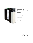
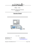
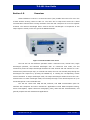
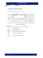
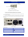
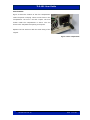
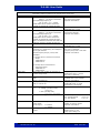
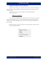
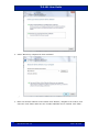
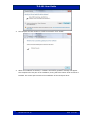
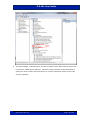
TLS-101
Tunable Laser Source
C-Band
User Guide
Version: 1.2
Date: June 22, 2015
TLS-101 User Guide
General Photonics Corporation is located in Chino California.
For more information visit the company's website at:
www.generalphotonics.com
or call 909-590-5473
GP-UM-TLS-101-12
Page 2 of 50
TLS-101 User Guide
SAFETY CONSIDERATIONS
The following safety precautions must be observed during operation of this product.
Failure to comply with these precautions or with specific warnings elsewhere in this manual
violates safety standards of design, manufacture, and intended use of the product. General
Photonics assumes no liability for customers’ failure to comply with these requirements.
Before operation, the user should inspect the product and review the manual carefully.
Properly ground the chassis and work space using the chassis ground terminal.
Use only in a safe work environment in terms of temperature, humidity, electrical power and risk
of fire or shock. The product is designed for indoor use. Avoid exposure to liquids or water
condensation. Provide adequate ventilation for cooling.
Operate the product on a stable surface. Avoid excess vibration.
Standard laser safety procedures should be followed during operation.
Never look into the light source fiber connector when the light source is
turned on. THE OUTPUT LIGHT FROM A HIGH POWER LASER IS HARMFUL
TO HUMAN EYES. Follow industry standard procedures when operating a
high power laser source.
GP-UM-TLS-101-12
Page 3 of 50
TLS-101 User Guide
GP-UM-TLS-101-12
Page 4 of 50
TLS-101 User Guide
Section 1.0
Overview ............................................................... 7
Section 2.0
Features ................................................................ 8
2.1 Front Panel and Optical Output ............................................... 8
Fiber Connectors ............................................................................9
Ferrule Cleaning Procedure ............................................................9
2.2 Rear Panel: Electrical and Remote Control Interfaces ........... 10
Section 3.0
Operation Instructions ........................................ 12
3.1 Unpacking ............................................................................. 12
3.2 Front Panel Operation ........................................................... 12
3.3 Operation Modes ................................................................... 13
Continuous Scan...........................................................................13
Manual Scan .................................................................................15
Single Wavelength .......................................................................16
Select Wavelength .......................................................................17
Set GPIB Address .........................................................................18
3.4 Troubleshooting .................................................................... 19
Front Panel Operation ..................................................................19
Remote Control ............................................................................20
Section 4.0
Specifications ..................................................... 21
Optical..........................................................................................21
Electrical/Communication ............................................................21
Physical and Environmental .........................................................22
Appendices ................................................................................. 23
Appendix 1.0 Remote Control Commands.................................... 23
Command List ..............................................................................23
Appendix 2.0 RS-232 connection and setup ................................ 28
Appendix 3.0 USB connection and setup ..................................... 29
GP-UM-TLS-101-12
Page 5 of 50
TLS-101 User Guide
USB Driver Installation ................................................................29
Appendix 4.0 Ethernet setup....................................................... 35
LabView Program .........................................................................36
Command List for Ethernet Setup.................................................39
Guidelines for Ethernet Setup ......................................................40
Appendix 5.0 GPIB setup and control.......................................... 41
Setting the GPIB Address .............................................................41
GPIB Control ................................................................................41
Appendix 6.0 LabView Control Programs .................................... 42
RS-232/USB/GPIB .......................................................................42
Ethernet .......................................................................................47
Appendix 7.0 ITU Grid Channel Lookup Table ............................. 48
GP-UM-TLS-101-12
Page 6 of 50
TLS-101 User Guide
Section 1.0
Overview
General Photonics’ TLS-101 is a continuous wave (CW) tunable laser source for use in the
C-band window covering 1528 to 1563 nm. The laser can be step-tuned across the C-band
communication channels with a tuning resolution of 50 GHz and a step time of 20 ms for adjacent
channels. The internal wavelength locker ensures that the wavelengths or frequencies of the
output light are exactly on the ITU grid of the DWDM channels.
Figure 1 TLS-101 Tunable Laser source
The TLS-101 has four different operation modes: continuous scan, manual scan, single
wavelength operation, and selected wavelength scan. In continuous scan mode, the TLS
continuously scans the output wavelength between the start channel and end channel at a userselected rate (dwell time per step). In manual scan mode, the user can manually step through the
wavelength scan sequence by pressing the ENTER key or sending the corresponding remote
control command. In single wavelength mode, the output wavelength remains fixed at the userselected value. In select wavelength mode, the TLS steps through a user-stored sequence of up to
40 wavelengths at a user-selectable rate.
The TLS-101 comes with USB, RS-232, Ethernet, and GPIB communication ports for
interface with computers and other instruments. Applications include WDM component testing,
sensor interrogation, optical coherence tomography (OCT), PMD and PDL characterization, and
general-purpose test and measurement applications.
GP-UM-TLS-101-12
Page 7 of 50
TLS-101 User Guide
Section 2.0
Features
2.1 Front Panel and Optical Output
The front panel of the TLS-101 is shown in Figure 2.
Figure 2 TLS-101 front panel
Front panel features:
LCD display:
Displays operation mode and control parameters
Power:
Power on/off switch
Light:
Light source safety key
Light Output:
FC/APC adapter for laser output (PM)
MODE:
Select operation mode or parameter setup
ENTER:
Select option or confirm setting
▲
◄
►:
Navigate selections or set values
▼
GP-UM-TLS-101-12
Page 8 of 50
TLS-101 User Guide
Fiber Connectors
The TLS-101 has one connector adapter on the front panel for light source output. The
standard output is PM fiber with a narrow key FC/APC connector. The adapter is a universal
connector interface (UCI), which features a male-type adapter top piece that can be removed for
direct access to the ferrule end for routine cleaning and maintenance without removing the entire
adapter from the panel. This feature helps avoid high insertion loss, high return loss and
measurement instability caused by dirty or contaminated connectors. In addition, the universal
interchangeable adapter allows the user to switch to ST, SC, or FC connectors without opening the
instrument panel. Although the TLS-101 is shipped with an FC fiber adapter, other interchangeable
inserts are available. For additional information on different input fiber adapter inserts, please
contact General Photonics.
External fiber connectors should be cleaned using industry standard cleaning methods
before connection to the TLS-101. If this procedure is followed before each connection, the
instrument’s internal connector ferrules should not need regular cleaning. However, high insertion
loss or measurement instability that does not improve after cleaning the external connectors may
indicate that the instrument’s internal connector ferrules require cleaning.
Ferrule Cleaning Procedure
The connector ferrule is contained in a universal connector interface consisting of a front
piece that connects to the external fiber connector, and a base piece that is mounted on the front
panel of the instrument, as shown in Figure 3. To clean a connector ferrule, first, make sure no
external connector is connected to the universal connector interface. Then, using a Phillips
screwdriver, remove the two small screws connecting the front and back parts of the adapter, and
carefully pull the front flange straight out. (Note: never remove the adapter base from the front
panel). The ferrule end should now be exposed. Clean the ferrule using standard cleaning
procedures (compressed air or a fresh lint-free tissue and alcohol or other connector-cleaning
solvent), taking care to avoid scratching the ferrule surface. Finally, replace the front flange
(position it so that the key notch faces up, and the small alignment pin lines up with the hole in
the base piece, before pushing it in) and the screws. For frequent measurements, we recommend
that the user prepare a patch cord fiber to avoid wear on the internal connector.
GP-UM-TLS-101-12
Page 9 of 50
TLS-101 User Guide
Hole for
alignment pin
Remove screws
Front flange
Adapter basedo not remove
Ferrule end
Figure 3 Diagram of universal connector interface
2.2 Rear Panel: Electrical and Remote Control Interfaces
The AC power plug, fuse, and communication interface connectors are mounted on the
rear panel, as shown in Figure 4.
The TLS-101 includes RS-232, USB, Ethernet, and GPIB interfaces for external computer
operation of the system. Control commands and remote interface setup information are located in
the appendices.
Figure 4 rear panel
Rear Panel Features:
USB interface port
Line: External AC input connector
RS-232 serial interface port
Cooling fan air outlet
Ethernet interface port
: Chassis ground
BNC: not used in TLS-101
GPIB interface port
GP-UM-TLS-101-12
Page 10 of 50
TLS-101 User Guide
Fuse location:
Figure 5 shows the location of the fuse compartment
under the power cord plug. There are two fuses in the
compartment- the one in use and a spare. The fuse
further inside the compartment is active. The one
closer to the compartment opening is the spare.
Replace the fuse with one with the exact rating of the
original.
Figure 5 Fuse compartment
GP-UM-TLS-101-12
Page 11 of 50
TLS-101 User Guide
Section 3.0
Operation Instructions
3.1 Unpacking
Inspect TLS-101 for any physical damage due to shipping and transportation. Contact
carrier if any damage is found. Check the packing list to see if any parts or accessories are
missing.
Packing List
Item #
Description
1
TLS-101
2
Power cord
3
RS-232 cable (straight-wired)
4
USB cable
6
User guide
7
Software cd
3.2 Front Panel Operation
1.
Connect power cord and plug it into wall receptacle. Make sure the ground pin of the
power cord is connected to earth ground.
2.
Connect a fiber to the output connector of the TLS-101. It is important to clean the fiber
connector using industry standard procedures and to make sure that the connection is
good. Make sure that the laser is turned off during connector cleaning.
3.
Power on the instrument and turn the safety key to the “on” position. The TLS-101 will run
through a brief initialization sequence and then display the operation mode selection
screen.
General Photonics
TLS-101, Ver1.5 C
Initialization screen
1. CONTINUOUS SCAN
2. MANUAL SCAN
First two options on mode selection screen
GP-UM-TLS-101-12
Page 12 of 50
TLS-101 User Guide
3.3 Operation Modes
When the TLS-101 is first powered on, the default display is the mode selection screen.
The MODE key can also be used at any time to return to the mode selection screen.
The TLS-101 has 5 options available under its mode selection screens, with 2 options
listed on each screen. The current mode is highlighted. The default operation mode is continuous
scan mode or the mode used last. Use the UP and DOWN arrows to move between options, and
the ENTER key to select the highlighted option. The mode selection screens are shown below.
1. CONTINUOUS SCAN
2. MANUAL SCAN
3. SINGLE WAVELENGTH
4. SELECT WAVELENGTH
5. SET GPIB ADDR
When the instrument is powered off, current settings are saved for use the next time the
instrument is powered on.
Continuous Scan
In continuous scan mode, the TLS-101 scans between the designated start and end
channels, with a user-specified rate, sweep pattern, and number of cycles.
Setup for continuous scan is as follows:
1.
Set scan start point:
Start: 01 (191.70THz)
λ: 1563.86nm
The top line shows the ITU grid channel and the frequency corresponding to the
selected channel. The bottom line shows the wavelength corresponding to the selected
channel. Use the arrow keys to set the desired channel number. The ◄ and ► keys
move the cursor between digits, and the ▲ and ▼ keys increment and decrement the
active digit. Once the value is set, press the ENTER key to execute the setting and
proceed to the next setup step.
Start Channel Range: 1 to 89 for C band laser
GP-UM-TLS-101-12
Page 13 of 50
TLS-101 User Guide
2.
Set scan end point:
End: 89 (196.10THz)
λ: 1528.77nm
The top line shows the ITU grid channel and the frequency corresponding to the
selected channel. The bottom line shows the wavelength corresponding to the selected
channel. Use the arrow keys to set the desired channel number. The ◄ and ► keys
move the cursor between digits, and the ▲ and ▼ keys increment and decrement the
active digit. Once the value is set, press the ENTER key to execute the setting and
proceed to the next setup step.
End Channel Range: 1 to 89 for C band laser
3.
Set step size and dwell time per step:
Step:
Dwell:
1x 50 = 50GHz
200 ms/step
The top line shows the step size setting, as a multiple of ITU grid channels. The
bottom line shows the dwell time per step. Use the arrow keys to set the step size
(number of channels per step), then press ENTER to move the cursor to the bottom
line. Set the dwell time per step, then press ENTER to move to the next setup step.
Step Size Range (# of channels per step): 1 to 89 for C band laser
Dwell Time Range: 20 to 60,000 ms/step
4.
Set scan pattern and number of cycles:
Trace: SAW Cycle: 50
↓
Trace: SAW Cycle: 50
ENTER key to start
There are two available scanning patterns (traces). If SAW is selected, a scan cycle
consists of a scan from the start point to the end point. After the end of each cycle,
the TLS-101 skips back to the start point, creating a sawtooth pattern. If TRI is
selected, a scan cycle consists of a round trip from the start point to the end point and
back to the start point, creating a triangle pattern. Use the ▲ and ▼ keys to select the
desired trace. Press the ENTER key to move to cycle setup. Use the arrow keys to set
the desired number of cycles (or set cycle number to Inf for unlimited scanning), then
press ENTER to start the scan.
Trace options: SAW, TRI
Cycle Range: 1 to 999 or Inf
GP-UM-TLS-101-12
Page 14 of 50
TLS-101 User Guide
While the scan is running, the screen will show the scan mode, the current channel,
and the current wavelength.
CONTINUOUS SCAN
CH: xx λ: xxxx.xx nm
o
Laser status indicator:
o = laser on
x = laser off
The laser status indicator in the upper right corner of the screen indicates whether the
laser is on or off. During normal operation, it should display an “o”.
The MODE key can be used at any time to stop the scan and return to the mode
selection menu.
Manual Scan
The manual scan is a manually triggered fixed-sequence scan. The setup and available
scan patterns are the same as for continuous scan, but in manual scan mode, the TLS-101 moves
to the next wavelength in the scan each time the ENTER key is pressed.
Setup for manual scan is as follows:
1.
Set scan start point:
Start: 01 (191.70THz)
λ: 1563.86nm
The top line shows the ITU grid channel and the frequency corresponding to the
selected channel. The bottom line shows the wavelength corresponding to the selected
channel. Use the arrow keys to set the desired channel number. The ◄ and ► keys
move the cursor between digits, and the ▲ and ▼ keys increment and decrement the
active digit. Once the value is set, press the ENTER key to execute the setting and
proceed to the next setup step.
Start Channel Range: 1 to 89 for C band laser
2.
Set scan end point:
End: 89 (196.10THz)
λ: 1528.77nm
The top line shows the ITU grid channel and the frequency corresponding to the
selected channel. The bottom line shows the wavelength corresponding to the selected
channel. Use the arrow keys to set the desired channel number. The ◄ and ► keys
move the cursor between digits, and the ▲ and ▼ keys increment and decrement the
active digit. Once the value is set, press the ENTER key to execute the setting and
proceed to the next setup step.
End Channel Range: 1 to 89 for C band laser
GP-UM-TLS-101-12
Page 15 of 50
TLS-101 User Guide
3.
Set step size:
Step:
1x 50 = 50GHz
Use the arrow keys to set the step size (number of channels per step), then press
ENTER to move to the next setup step.
Step Size Range (# of channels per step): 1 to 89 for C band laser
4.
Set scan pattern:
Trace: Saw
ENTER key to start
There are two available scanning patterns (traces). If Saw is selected, a scan cycle
consists of a scan from the start point to the end point. After the end of each cycle,
the TLS-101 skips back to the start point, creating a sawtooth pattern. If Triangle is
selected, a scan cycle consists of a round trip from the start point to the end point and
back to the start point, creating a triangle pattern. Use the ▲ and ▼ keys to select the
desired trace. Press the ENTER key to start the scan.
Trace options: Saw, Triangle
While the scan is running, the screen will show the scan mode, the current channel,
and the current wavelength.
MANUAL SCAN
CH: xx λ: xxxx.xx nm
o
Laser status indicator:
o = laser on
x = laser off
Press the ENTER key to advance to the next wavelength in the scan sequence.
The laser status indicator in the upper right corner of the screen indicates whether the
laser is on or off. During normal operation, it should display an “o”.
The MODE key can be used at any time to stop the scan and return to the mode
selection menu.
Single Wavelength
In single wavelength mode, the TLS-101 outputs a fixed wavelength signal at the selected
channel. The wavelength selection screen is displayed below.
Set CH: 01 (191.70THz)
λ: 1563.86nm
The top line shows the ITU grid channel and the frequency corresponding to the selected
channel. The bottom line shows the wavelength corresponding to the selected channel. Use the
arrow keys to set the channel number and press ENTER to execute the setting.
GP-UM-TLS-101-12
Page 16 of 50
TLS-101 User Guide
Channel Range: 1 to 89 for C band laser
SINGLE WAVELENGTH o
CH: xx λ: xxxx.xx nm
Laser status indicator:
o = laser on
x = laser off
The display will show the operation mode (single wavelength) and current channel, and
the laser status indicator will show an “o” if the laser is on. Note that the wavelength cannot be
changed from this screen. To select a different wavelength, use the MODE key to return to the
mode selection menu.
Select Wavelength
In select wavelength mode, the TLS-101 steps through a user-input sequence of up to 40
wavelengths.
Setup for a selected wavelength scan is as follows:
1.
Input wavelength sequence:
BK1: 01 (1563.86nm)
→Key to Select BK
The top line shows the memory bank position (BK1) and the ITU grid channel setting
and corresponding wavelength. Use the left, up, and down arrow keys to set the
desired channel number for BK1. The ◄ arrow key moves the cursor between digits,
and the ▲ and ▼ arrows increment and decrement the active digit. The ► arrow key
moves to the next memory bank position.
BK2: 10 (1560.20nm)
→Key to Select BK
Channel Range: 1 to 89 for C band laser
Number of memory bank positions: up to 40
2.
Repeat step 1 as many times as necessary to input a wavelength sequence of up to 40
values. Note that the amount of time spent at a particular wavelength can be
controlled by inputting the same wavelength channel to multiple consecutive BK
positions. It is not necessary to use all 40 BK positions. When the sequence is entered,
press ENTER to move to the next step.
3.
Set dwell time:
Dwell: 1000 ms/step
Enter key to start
Use the arrow keys to set the dwell time at each step (BK position).
GP-UM-TLS-101-12
Page 17 of 50
TLS-101 User Guide
Dwell Time Range: 20 to 60,000 ms/step
Press ENTER to start the scan.
SELECT WAVELENGTH o
CH: xx λ: xxxx.xx nm
Laser status indicator:
o = laser on
x = laser off
While the scan is running, the screen will show the scan mode, the current channel,
and the current wavelength.
The laser status indicator in the upper right corner of the screen indicates whether the
laser is on or off. During normal operation, it should display an “o”.
The sequence will keep repeating as long as the scan is running. The MODE key can be
used at any time to stop the scan and return to the mode selection menu.
Set GPIB Address
Option 5 allows the user to set the instrument’s GPIB address. When this option is
selected, the LCD displays the current GPIB address information, as shown below:
GPIB ADDR: 05
Use the arrow keys to set the GPIB address, and press ENTER to save the setting.
GPIB Address Range: 1 to 30
GP-UM-TLS-101-12
Page 18 of 50
TLS-101 User Guide
3.4 Troubleshooting
Front Panel Operation
1.
No light output (safety key off): The laser cannot turn on if the safety key is in the “off”
position. If the key is off, once the user completes setup for an operation mode and
attempts to enter the operation mode, the TLS-101 will display the following error
message:
TLS is not ready,
Light key is OFF!
If this message appears, turn the key to the “on” position, wait a few seconds, and repeat
the setup.
2.
Laser not ready: If the TLS-101 is put into an operation mode before it has completed its
initialization, it will display the following error message:
TLS is not ready,
Please try again!
If this message appears, wait several seconds and try the operation again. If the error
message persists, even after power cycling the instrument, the TLS-101 may need repair.
3.
Incorrect setup: The continuous and manual scan functions may not run if the difference
between the start and end point channels is not a multiple of the step size. In this case,
the following error screen may appear:
Setting error!
If this message appears, modify the scan settings so that they are internally consistent.
4.
Light turns off during operation: If, for some reason, the laser turns off once an operation
is started, the light status indicator in the upper right corner of the operation screen will
change from an “o” to an “x”.
SINGLE WAVELENGTH x
CH: 35 λ: 1550.12 nm
Laser status indicator:
o = laser on
x = laser off
This can happen for several reasons, such as the safety key being turned off during
operation, or a “turn off laser” remote control command being sent. If the laser status
indicator changes state unexpectedly, check the safety key and redo the setup. If the
message persists, contact General Photonics.
5.
Unstable light output: Make sure that the TLS-101 has been allowed to warm up for 0.5-2
minutes when first powered on. Check connectors to make sure that connector types are
GP-UM-TLS-101-12
Page 19 of 50
TLS-101 User Guide
correct, connectors are clean, and connections are good. If necessary, add an isolator
after the TLS.
6.
Optical output power lower than expected: Make sure that the output fiber connector type
matches the TLS-101’s output fiber connector type, that all connectors and adapters are
clean, and that connections are good.
Remote Control
Command Format
1.
If the beginning (“*”) or ending identifiers (“#” or “?”) of a command are missing, the
instrument will not respond.
RS-232
1.
Make sure that the cable is straight-wired (pin-to-to pin wired) not cross-wired.
2.
Verify active Comm Port (COM1, COM2, etc.).
3.
Verify Comm Port settings: 8 data bits, 1 stop bit, no parity bits, baud rate 9600.
USB
1.
Make sure that the USB driver is installed before communicating via USB.
Ethernet
1.
Make sure that the Ethernet communication setting (Static or Dynamic) matches the
Ethernet addressing type being used.
2.
Make sure that the cable type is correct: cross-linked cable for static IP with direct
instrument-to-computer connection, straight-linked cable for connection through a switch
or router (for either static or dynamic IP).
GP-UM-TLS-101-12
Page 20 of 50
TLS-101 User Guide
Section 4.0
Specifications
Optical
Wavelength/Frequency
Tuning Range
Number of ITU Channels
C band
1528.77 to 1563.86 nm
191.7 to 196.1 THz
89
Tuning Resolution
(Minimum Step Size)
Optical Power
50 GHz
Power Ripple
(over tuning range)
Side Mode Suppression Ratio
(SMSR)
Output Linewidth (Lorentz)
0.3 dB typical
0.5 dB max.
>40 dB
13 dBm
<5 MHz (1 MHz typical)
Average Relative Intensity Noise
(RIN)
(10 MHz-1GHz)
(1-10 GHz)
OSNR (0.1 nm bandwidth)
<−110 dB/Hz
<−145 dB/Hz
> 50 dB
Polarization Extinction Ratio
>20 dB
Return Loss
> 40 dB
Locked Frequency Accuracy
−1.8 to 1.8 GHz
Shuttered Output Power
<−30 dBm
Tuning Speed
20 ms for adjacent channels
Operating Modes
Single wavelength output
Single trip and round trip wavelength scanning
User-defined sequence scan
Electrical/Communication
Front panel display
2x20 LCD display
Power Supply
100-240VAC, 50-60 Hz
Communication Interfaces
RS-232, USB, Ethernet, GPIB
GPIB Address
1-30
RS-232 Baud Rate
9600
GP-UM-TLS-101-12
Page 21 of 50
TLS-101 User Guide
Physical and Environmental
Optical Connectors
Standard 2U half-19” rack mount size1
14” (L) × 8.5” (W) × 3.5” (H)
PM FC/APC connector
Weight
7 lb
Operation temperature
5 to 50°C
Storage Temperature
0 to 70°C
Dimensions
1.
Rack mount kit available. Contact General Photonics for details.
GP-UM-TLS-101-12
Page 22 of 50
TLS-101 User Guide
Appendices
The following appendices include the remote control command lists, as well as setup
information for different control interfaces.
Appendix 1.0 Remote Control Commands
The commands and responses listed in Table 1 and Table 2 are the same for all
communication protocols: RS-232, USB, Ethernet, and GPIB.
Only one command string can be sent at a time. Commands are not case sensitive.
Command List
Table 1 Remote Control Commands
Command
*IDN?
*VER?
*IND?
*IND 1#
System Commands
Description
Query product identification.
Query the firmware version
Query parameter indicator
enable/disable status.
1 = enabled
0 = disabled
Indicator status resets to disabled at
power-up.
Enable parameter indicators. With
indicators enabled, responses to query
commands will include parameter labels
before the values. Indicators do not
affect the front panel display.
Response
*GP-TLS-101 C-band#
*V1.5 20150612# (may vary)
*0# (indicators off)
*IND 1# (indicators on)
*0#
(indicators off)
*E00#
Example: Wavelength query response
with
Indicator enabled: *WAV 1550.12#
Indicator disabled: *1550.12#
*IND 0#
*ADR nn#
*ADR?
*RST#
Indicator status resets to disabled at
power-up.
Disable parameter indicators.
(Default state on instrument power-up)
Set GPIB address.
For example: *ADR 05#
Value stored in non-volatile memory.
Range 1 – 30. Default: 5
(Do not send this command via GPIB)
Query the current GPIB address.
Value stored in non-volatile memory.
Range 1 – 30. Default: 5
System reset. Runs power-up
initialization sequence and resets laser.
GP-UM-TLS-101-12
*E00#
*E00#
Sample response:
*ADR 05# or *05#
Page 23 of 50
TLS-101 User Guide
Command
*CHN n#
*CHN?
*FRQ?
*WAV?
*STA n#
*STA?
Command
*WAV n?
*FRQ n?
*CHN:MAX?
*POW?
Command
*SWP:MOD n#
*SWP:MOD?
Operation Status Queries/Commands
Description
Response/Example
Sets laser to ITU grid channel n and turns
*E00#
on the laser.
n=1~89 for C band.
This command automatically switches the
TLS-101 to single-wavelength operation
(Sweep mode 3).
Query the current ITU grid channel.
Sample response:
Can be sent from any mode, including
*CHN 12# or *12#
during sweep operation.
Does not affect operation mode.
Query the current frequency.
Sample response:
Can be sent from any mode, including
*FRQ 192.50# or *192.50#
during sweep operation.
Does not affect operation mode.
Query the current wavelength.
Sample response:
Can be sent from any mode, including
*WAV 1550.12# or #1550.12#
during sweep operation.
Does not affect operation mode.
Sample command: *STA 1# = ON
Turn the laser source ON or OFF.
Response: *E00#
n=
0: OFF
*E15# if key is Off
1: ON
Note: ON/OFF command only works when
the laser safety key is ON.
Laser will turn OFF if key is turned OFF, but
will not automatically turn ON when key is
turned back on.
In general, this command is not required as
part of operation setup. The laser will turn
on when an operation mode is started.
Query the ON/OFF status of the laser.
*STA 0#: laser OFF (Software Ctrl)
Possible states:0=OFF, 1=ON
*STA 1#: laser ON (Software Ctrl)
The laser will only turn on when an
*E15# if key is Off
operation mode is enabled. It remains off
during setup.
Reference and Lookup Table Queries
Description
Response/Example
Query the wavelength corresponding to ITU
Sample response:
grid channel n.
*WAV 1552.12# or *1552.12#
All units in nm
Query the frequency corresponding to ITU
Sample response:
grid channel n.
*FRQ 193.15# or *193.15#
All units are in THz
Query the total number of channels.
*CHN:MAX 89# or *89#
89 for a C band laser.
Query the specified output power of the
Sample command:*POW 13.50#
laser.
All units are in dBm.
Operation Mode Selection
Sweep mode selection/query
Description
Response/Example
*E00#
Sets sweep mode:
0: Manual mode
1: Continuous mode
2: Selected wavelength mode
3: Single wavelength mode (no sweep)
Notes:
1. The laser turns off when this
command is received.
2. For sweep modes 0, 1, or 2, this
command is required. For singlewavelength operation (mode 3), this
command is not required.
Query sweep mode.
GP-UM-TLS-101-12
*SWP:MOD 1# or *1#
Page 24 of 50
TLS-101 User Guide
Command
*SWP:BGN n#
*SWP:BGN?
*SWP:END n#
*SWP:END?
*SWP:STE n#
Wavelength Sweep Commands
Commands related to continuous or manual sweep mode setup.
Description
Response/Example
Sets the start channel for a sweep.
Sample command: *SWP:BGN 5#
Range n: 1 to 89 for C band laser.
Start sweep from CHN 5.
Corresponding frequency is
Response: See table 2.
191.70 THz + (n-1) × 50GHz.
*CHN:MAX? can be used to confirm the
number of channels for a particular laser.
Query the start channel for the sweep.
Sample response:
*SWP:BGN 05# or *05#
Sets the end channel for a sweep.
Sample command: *SWP:END 20#
Range n: 1 to 89 for C band laser.
End sweep at CHN 20.
Corresponding frequency is
Response: See Table 2.
191.70 THz + (n-1) × 50GHz.
*CHN:MAX? can be used to confirm the
number of channels for a particular laser.
Note: The difference between start and end
channels must be a multiple of step size.
Query the end channel for the sweep.
Sample response:
*SWP:END 20# or *20#
Example: n =5
Sets the step size for sweep modes 0
Step size is 5 channels.
(manual) or 1 (continuous), as a multiple n
Frequency step: 5x50 = 250 GHz
of ITU grid channels.
Response: see Table 2.
Actual frequency step is (n X 50) GHz.
Examples:
1. Set step size as 1 channel for manual
sweep:
*SWP:MOD 0#
*SWP:STE 1#
*SWP:STE?
*SWP:DWE n#
*SWP:DWE?
*SWP:REP n#
*SWP:REP?
*SWP:CYC n#
*SWP:CYC?
2. Set step size as 5 channels for
continuous sweep:
*SWP:MOD 1#
*SWP:STE 5#
Query step size (number of channels) for
current sweep mode.
Sets the dwell time per step for continuous
scan.
Range: 20-60000 ms
Query dwell time per step for continuous
scan, in units of ms.
Sets the scanning pattern (trace).
n=
0: Triangle (round trip scan)
/\/\/\/\/\/\
1: Saw (one-way scan)
/| /| /| /| /| or \|\|\|\|
Query the scanning pattern.
Sets the number of cycles for continuous
sweep mode.
Cycle range n:
1 to 999 or
0 = Infinite
Query cycle number setting for continuous
sweep.
GP-UM-TLS-101-12
Sample response:
*SWP:STE 5.00# or *5.00#
Step size is 5 channels.
Sample command: *SWP:DWE 100#
Set dwell time to 100 ms/step.
Response: see Table 2.
Sample response:
#SWP:DWE 100# or *100#
Dwell time is 100 ms/step.
Response: see Table 2.
Possible Responses: 0 or 1
*0#: Triangle Sweep
/\/\/\/\/\/\
*1#: Saw Sweep
/| /| /| /|
Sample command: *SWP:CYC 0#
Number of cycles is infinite
Response: see Table 2.
Sample response:
*SWP:CYC 5# or *5#
Sweep cycle setting is 5.
Page 25 of 50
TLS-101 User Guide
Command
*SEL:BKb chn#
Select Wavelength Commands
Commands related to selected wavelength sequence setup.
Description
Response/Example
Sample command:
Store wavelength channels for selected
*SEL:BK5 22#
wavelength scan.
Store channel 22 in Bank 5.
b: Memory bank location
chn: ITU grid channel to be stored in
Responses:
selected memory bank location.
*E00# No error
(The stored values cannot be queried)
*E14# Command conflict
Storage Bank Range: BK1 to BK40.
(TLS-101 is not in mode 2)
Channel Range: 1 to 89 for C band laser.
Notes:
1. Legacy command *SEL:CHb chn# has
the same function and is still supported.
2. Command only valid in mode 2 (selected
wavelength scan).
To set a wavelength sequence for selected
wavelength scan, this command should be
used to consecutively designate the
wavelength channels for memory locations
1 to the desired end location.
Sample sequence:
*SEL:BK1 1#
*SEL:BK2 5#
●
●
●
*SEL:BK15 80#
sets up a sequence of 15 wavelengths for
selected wavelength scan.
When the start command is received, the
TLS steps through memory bank locations
from location 1 to the last bank location
set.
*SEL:DWE n#
*SEL:DWE?
If bank locations in the sequence are
skipped, the TLS-101 will use default values
for empty banks. To avoid unpredictable
sequences, wavelengths should be
designated for all memory locations to be
used.
Set the dwell time per step in Selected
Wavelength Mode.
Range for n: 20 to 60000 ms
Query the dwell time per step for Selected
Wavelength Mode.
GP-UM-TLS-101-12
Sample command: *SEL:DWE 100#
Sets dwell time per step to 100 ms.
Note that this is a different variable
than the dwell time for continuous
scan.
Sample response:
*SEL:DWE 100# or *100#
Dwell time per step is 100 ms.
Page 26 of 50
TLS-101 User Guide
Command
SWP:STA n#
*SWP:NEXT#
Sweep Operation Commands
Commands related to sweep mode operation after setup is finished.
Description
Response/Example
*E00#: OK
Set sweep status.
*E01#: Command error
Stop, start, pause or continue a paused
*E13#: Parameter setting error; the
scan. Command only applicable in sweep
difference between the
modes 0 (manual sweep), 1 (continuous
starting and ending channel is
sweep) and 2 (selected wavelength sweep).
not a multiple of the step size.
*E14#: Command conflict;
0: Stop sweep
0 (stop) can be sent while a scan
1: Start (or restart, if paused): laser will
is running
start sweep from beginning channel.
1 (start/restart) can be sent while
2: Pause a sweep in progress
a scan is stopped or paused
3: Continue a paused sweep from the
3 (pause) can be sent while a scan
channel at which it was paused.
is running
4 (continue) can only be sent while
Note: Starting a sweep automatically turns
a scan is paused.
the laser on. Continuing a paused sweep
*E15#: TLS is not ready or safety key
does not.
is off.
Advance to the next wavelength channel in
*E00#: OK step executed.
a manual scan.
*E14#: Command conflict; TLS-101
Valid in sweep mode 0 (manual) only.
not in manual scan mode.
Table 2 Command Response Codes
E00
E01
E02
E03
E04
E05
E06
E13
E14
E15
No error (Correct command received)
Undefined command
Missing parameter
Invalid syntax in command string
String of characters too long (>buffer limit)
Parameter has too many digits after the decimal point
Parameter value out of range
Parameter setting error. The difference between start and end channel numbers is not
a multiple of the step size.
Command conflict. Command incompatible with current operation mode.
TLS laser safety key is off. (This state overrides all other states)
Notes on command list:
1. The TLS-101 can include a command indicator in query responses that identifies the query command
to which the response is related. To enable this feature, set the indicator response to “on” by sending
the command: *IND 1#. With indicators disabled (the default state), only the queried value will be
returned.
2. For single-wavelength operation only the *CHN n# command is necessary. This command puts the
TLS-101 into single-wavelength operation mode, sets the laser channel to n, where n is an ITU grid
channel, and turns on the laser. It is not necessary to set the sweep mode first.
3. For all sweep modes, the setup sequence should be:
a. Set sweep mode (*SWP:MOD n#).
b. Set sweep operation parameters. The recommended command sequence is the order used
for front panel setup for the corresponding mode. Using this command sequence ensures
that all variables are set to the desired values, and avoids unexpected effects from the use of
default or “leftover” variables from previous setups.
c. Start sweep (SWP:STA 1#).
GP-UM-TLS-101-12
Page 27 of 50
TLS-101 User Guide
Appendix 2.0 RS-232 connection and setup
1.
The RS-232 connector on the rear panel of the TLS-101 is a DB9 male connector. Use a
straight (not cross connected) RS-232 cable with DB9 female connectors to connect the
TLS-101 to the control computer.
GND
RXD
TXD
5 4 3 2 1
9 8 7 6
Figure 6 RS-232 connector pin assignment on TLS-101 rear panel.
2.
Power on the instrument.
3.
Send a command string to the instrument (See Appendix 1 for commands. Any program
that supports RS-232 communication protocols can be used to send ASCII commands to
the instrument. Many programming languages support serial communications, including
Visual Basic, LabView and C.
RS-232 settings:
RS-232 port uses asynchronous framing, 8 data bits, no parity bit, and 1 stop bit.
RS-232 baud rate: 9600 bps.
GP-UM-TLS-101-12
Page 28 of 50
TLS-101 User Guide
Appendix 3.0 USB connection and setup
USB drivers are included in the “VCP” folder on the cd. They need to be installed before
USB communication can be established. The first time the USB is used, insert the cd into the
control computer.
Connect the TLS-101 to the control computer using a standard USB cable.
Power on the TLS-101.
USB Driver Installation
The first time the computer detects a USB connection to the instrument, the driver may
install automatically (Windows 7/8) or a “Found New Hardware Wizard” window may appear
(Windows XP). If neither of these things occur, the driver can be located and installed using
Device Manager.
1.
Open Device Manager. Look for a new device under “Other Devices”. Right-click it and
select “Update Driver Software”.
↓
↓
GP-UM-TLS-101-12
Page 29 of 50
TLS-101 User Guide
2.
Select “Browse my computer for driver software”:
D:\USB Driver ;
3.
Make sure that the software cd is inserted. Click “Browse”, navigate to the cd drive, and
select the “VCP” folder. Make sure the “include subfolders” box is checked. Click “Next”.
GP-UM-TLS-101-12
Page 30 of 50
TLS-101 User Guide
4.
The computer will ask whether to install the software. Click “Install”.
5.
When the installation is finished, a “software successfully updated” message will appear.
This completes the first part of the installation, during which the USB to serial converter is
installed. The second part consists of the installation of the serial port driver.
GP-UM-TLS-101-12
Page 31 of 50
TLS-101 User Guide
6.
In Device Manager, “USB Serial Port” should now appear under “Other Devices. Right-click
it and select “Update Driver Software”. Follow the same procedure as described above to
specify the driver location and install the driver until the completion window for the USB
serial port appears:
GP-UM-TLS-101-12
Page 32 of 50
TLS-101 User Guide
7.
In “Device Manager”, there should now be a USB Serial Port listed under “Ports (COM &
LPT)”:
GP-UM-TLS-101-12
Page 33 of 50
TLS-101 User Guide
Note the port number that the TLS-101 is using (COM3, in this example).
The USB driver can drive more than one instrument, but the instruments will be connected
under different port numbers.
GP-UM-TLS-101-12
Page 34 of 50
TLS-101 User Guide
Appendix 4.0 Ethernet setup
There are two connection configurations for Ethernet control:
a) Static IP: the administrator assigns the instrument a fixed IP address. In this
mode the instrument can be directly connected to the control PC, as shown in
Figure 7, or can be connected through a router. For a direct connection (Figure 7),
a cross-linked network cable must be used. For a connection to a router, a
standard straight-linked network cable would be used.
b) Dynamic IP: the DHCP server assigns the instrument an available address when
requested. Connect the instrument with a DHCP server (running on router or
exchange server), as shown in Figure 8. For this configuration, a standard
straight-linked network cable must be used.
DHCP server
PC
TLS-101
Switch
PC
Figure 7 Direct connection: TLS-101 to PC
TLS-101
Figure 8 Connection with DHCP server
Once the physical connections are established, the instrument’s Ethernet configuration can
be set up.
GP-UM-TLS-101-12
Page 35 of 50
TLS-101 User Guide
LabView Program
A LabView program provided with the instrument can be used to set the Ethernet
communication mode, query the IP configuration, and perform static IP setup.
Open the LabVIEW program (SET_ETHERNET.vi or SET_ETHERNET.exe) to set the
Ethernet configuration.
This program was designed for an RS-232 interface, so the instrument should be
connected to the computer via RS-232 before running it. Please see the instructions in Appendix 2
for RS-232 setup. The program interface is shown below.
Select the correct serial (RS-232) port from the port configuration box at the top of the
screen. The baud rate should be set to 9600. Once these two parameters are set, click the white
arrow to run the program.
The program has 3 tabs. The first, “GET IP CONFIG” is used to query the current IP
configuration of the TLS-101. When the “Get IP Config” button at the left of the screen is clicked,
the program will read back the instrument’s current IP address, net mask, gateway, nameserver,
and port, as well as whether the instrument is currently set for static or dynamic IP addressing.
IP Config query screen- Static IP mode result
GP-UM-TLS-101-12
Page 36 of 50
TLS-101 User Guide
IP Config query screen- Dynamic IP mode result
Use this function to obtain the IP address, which is needed to control the instrument via
Ethernet.
The second tab, “MODE SETTING” allows the user to switch the instrument between static
and dynamic IP addressing modes.
Ethernet mode selection screen- dynamic
GP-UM-TLS-101-12
Page 37 of 50
TLS-101 User Guide
Ethernet mode selection screen- static
Clicking the “OK” button for dynamic mode puts the instrument into dynamic IP mode. The
instrument will obtain the dynamic IP information from the server. When it is finished, the
indicator for dynamic mode will turn green, and the Ethernet Mode status box will say “DYNAMIC”.
Clicking the “OK” button for static mode puts the instrument into static IP mode. The
instrument will recall the static IP settings from its memory. These can then be used for
communication. When it is finished, the indicator for static mode will turn green, and the Ethernet
Mode status box will say “STATIC”.
The TLS-101 writes its most recently saved static IP settings and its active mode to
memory. If it is powered off while in static mode, when it is powered back on, it will be in static
mode, and the most recently saved set of IP configuration information can be used for
communication.
If the TLS-101 is powered off while in dynamic IP mode, when it is powered back on, it will
be in dynamic IP mode.
The third tab in the program, “STATIC IP SETTING”, allows the user to set the static IP
configuration information. Input the information into the corresponding boxes and click the “SET”
button. As each value is written, its indicator turns green. When all of the information is
successfully stored, the “Set OK” indicator will turn green.
GP-UM-TLS-101-12
Page 38 of 50
TLS-101 User Guide
Static IP setup screen.
Command List for Ethernet Setup
The following commands can also be used for Ethernet setup. This set of commands is
case-sensitive and can be used with RS-232 only.
Set/Query Ethernet Mode
These commands are used to set or query the Ethernet addressing mode. Ethernet mode
setup must match the Ethernet setup for the control computer and the physical connection. There
are two choices:
Dynamic: the server will provide the address when requested.
Static: the user sets the address.
The Mode setting can be queried at any time.
Command
~7DHCP#
~6STIP#
~FMODE?#
Description
Set to dynamic IP mode
Set to static IP mode
Query Ethernet communication mode
Response
"OK”
"OK”
"DYNAMIC" if in Dynamic
"STATIC" if in Static
Dynamic IP
When the TLS-101 is set to dynamic IP mode, it will request the dynamic IP configuration
from the server. Allow a few seconds for this information to be retrieved before querying the
instrument.
Static IP
When the TLS-101 is set to static IP mode, the following commands can be used to
configure the static IP.
GP-UM-TLS-101-12
Page 39 of 50
TLS-101 User Guide
Command
~1:hhh.hhh.hhh.hhh#
~2:nnn.nnn.nnn.nnn#
~3:nnn.nnn.nnn.nnn#
~4:nnn.nnn.nnn.nnn#
~5:nnn#
~6STIP#
Description
Set IP Address. eg: ~1:192.168.2.106#
Set Net Mask. eg: ~2:255.255.255.0#
Set Gateway. eg: ~3:192.168.2.1#
Set NameServer. eg: ~4:192.168.2.2#
Set Port. eg: ~5:28#
Initialize the Static IP.
Required after setting all 5 addresses
Response
"OK"
"OK"
"OK"
"OK"
"OK"
"OK"
Configuration Query Commands
The following commands are used to query the IP setup. They will return either static or
dynamic values, depending on what mode the instrument is in, and, for static IP, whether the
setup was completed and initialized.
Command
~8IP?#
~BMASK?#
~CGATE?#
~DNAME?#
~EPORT?#
Description
IP Address
Get NetMASK
Get GateWay
Get NameServer
Get Port
Response
eg: 192.168.0.50
eg: 255.255.255.0
eg: 192.168.2.1
eg: 192.168.2.2
eg: 23
Notes on Ethernet setup commands:
1.
If a setup command is successful, the instrument will respond with “OK”. If not, it
will respond with “NO”.
2.
Allow sufficient time between commands. Dynamic IP mode requires the
instrument to communicate with the server, which can sometimes take several
seconds to respond.
Guidelines for Ethernet Setup
For static IP control, the net mask and gateway for the instrument should be the same as
those for the control computer. The first 3 groups of numbers in the IP address should be the
same as those for the control computer (192.168.2, for example). The last number can be any
available number, but cannot be the same as the IP address of the control computer. The range of
numbers is 1 to 254. If the computer’s IP address is 17, for example, the user can set the IP
address for the TLS-101 to any number in the range 1-254 except 17.
For static IP control, make sure that the control computer is also set to use a static
(defined) IP address (check the TCP/IP properties to find the computer’s Ethernet setup
information).
For dynamic IP control, make sure that the control computer is set to obtain its IP address
automatically. This information is also under TCP/IP properties.
•
To connect the instrument directly to a PC, use a PC to PC cable. To connect the
instrument to a LAN, use a standard network cable.
•
For Ethernet control, the serial port is only used during Ethernet setup.
GP-UM-TLS-101-12
Page 40 of 50
TLS-101 User Guide
Appendix 5.0 GPIB setup and control
Setting the GPIB Address
To set the instrument’s GPIB address:
Mode → Set GPIB Address (option 5)
GPIB ADDR: 05
Use the arrow keys to set the GPIB address, and press ENTER to save the setting.
Range:
1-30
GPIB Control
Connect the instrument to the computer with a GPIB cable. After determining/setting the
TLS-101’s GPIB address, enter it in the communication program being used. The instrument will
then be ready to receive commands. The command lists, responses, and error codes are given in
Table 1 and Table 2 in Appendix 1.
To ensure proper communication, use a GPIB cable that is fully compatible with the IEEE
488.1 standard. All GPIB/IEEE 488 interface connections must be made before turning on the
instruments.
GP-UM-TLS-101-12
Page 41 of 50
TLS-101 User Guide
Appendix 6.0 LabView Control Programs
LabView control programs are provided for remote control of the TLS-101. If LabView is
not installed on the control computer, install the LabView Run-Time engine (LV2012SP1_Run-time
engine), and the VISA driver (NIVISA1401runtime). These run-time engines are compatible with
Windows 8/7/XP.
For USB control, the USB drivers need to be installed. See Appendices 2-5 for details on
setup for specific communication interfaces.
Always close the control program before turning off the instrument.
RS-232/USB/GPIB
The control program “TLS_REMOTE.exe” (executable) is compatible with RS-232, USB and
GPIB interfaces. The program will auto-sense which interface is being used and display the
appropriate port configuration option. The control program interface is otherwise identical for RS232, USB and GPIB control.
Open the “TLS_REMOTE” program. Run the program by clicking the white arrow at the top
of the page. The program will search for available ports and display them in the port configuration
pull-down menu. If necessary, select “Refresh” from the pull-down menu to refresh the port list.
The COM port cannot be changed while the program is running. Stop the program, select a
communication port from the list, and run the program again.
(a) ASRLX::INSTR is the same as COMX for RS-232.
(b) GPIB::XX::INSTR refers to the GPIB port with an address of XX.
GP-UM-TLS-101-12
Page 42 of 50
TLS-101 User Guide
Continuous Scan Mode
The continuous scan mode tab allows the user to set up and run a continuous wavelength
scan (automatic scan at set rate). Set each parameter to the desired value, then click the
corresponding “SET” button. Note that displayed parameters are not necessarily the same as the
TLS-101’s current settings, and that a parameter value is not updated until its “SET” button is
clicked. To make sure settings are correct, reset all parameters before running a new scan.
Start Channel: Range: 1 to 89
End Channel:
Range: 1 to 89
Step Size:
Interval between consecutive channels in sweep
Unit: number of channels.
Range: 1 to 89
Note: Difference between start and end channels must be a multiple of the
step size.
Dwell Time:
Unit: ms
Range: 20 to 60000.
Scan Wave:
Options: Triangle (bidirectional) or Saw (unidirectional)
Cycle Number: Number of times to run the scan.
Range: 1 to 999 or 0 = infinite.
After each parameter is set, the “Response from TLS” box should show “*E00#”.
When all parameters are set, click “Start” to turn on the laser and start the scan. The
“Response from TLS” box should show “*E00#”. If it shows “*E13#”, the difference between the
GP-UM-TLS-101-12
Page 43 of 50
TLS-101 User Guide
start and end channels is not a multiple of the step size, and the scan will not run. Modify the
setup parameters before retrying the scan.
The “STOP” button stops a scan in progress. The scan should be stopped before switching
to a different operation mode.
Manual Scan Mode
The manual scan mode tab allows the user to set up and run a manual wavelength scan
(manually triggered step to the next wavelength in the series). Set each parameter to the desired
value, then click the corresponding “SET” button. Note that displayed parameters are not
necessarily the same as the TLS-101’s current settings, and that a parameter value is not updated
until its “SET” button is clicked. To make sure settings are correct, reset all parameters before
running a new scan.
Start Channel: Range: 1 to 89
End Channel:
Range: 1 to 89
Step Size:
Unit: number of channels.
Range: 1 to 89
Note: Difference between start and end channels must be a multiple of the
step size.
Scan Wave:
Options: Triangle (bidirectional) or Saw (unidirectional)
After each parameter is set, the “Response from TLS” box should show “*E00#”.
GP-UM-TLS-101-12
Page 44 of 50
TLS-101 User Guide
When all parameters are set, click “Start” to turn on the laser and start the scan. If the
setup is correct, the “Response from TLS” box should show “*E00#” and the laser will be set to
the start channel. If the response box shows “*E13#”, the difference between the start and end
channels is not a multiple of the step size, and the scan will not run. Modify the setup parameters
before retrying the scan.
Click the “NEXT” button to advance to the next wavelength (channel) in the series.
The “STOP” button stops a scan in progress. The scan should be stopped before switching
to a different operation mode.
Single Wavelength Mode
The single wavelength mode tab allows the user to set the laser for single-wavelength
operation. Set the output channel to the desired value (Range: 1 to 89 for a C band laser), and
click “OK”. The laser will be set to the desired channel and turned on.
The “STOP” button turns off the laser.
GP-UM-TLS-101-12
Page 45 of 50
TLS-101 User Guide
Selected Wavelength Mode
The selected wavelength scan mode tab allows the user to input a sequence of values for
the laser to step through. The “Scan Index” box shows the current memory location, and the “TLS
Channel #” box shows the ITU grid channel to be stored to that memory location. When this
function is first entered, the Scan Index will be 1. Set the TLS channel to the desired value and
click “SET”. If the set command is successful, the “Response from TLS” will be “*E00#”, and the
Scan Index will increment to 2. Repeat the process until the desired number of values has been
entered.
Note that the values in a sequence must be entered in order. If an error is made or a
previous entry needs to be corrected, the entire sequence must be re-entered. To do this, stop the
program (Stop Program button on left side of screen) and restart it (white arrow at top left of
screen) before selecting the “Selected Wavelength Mode” tab.
Set the dwell time per point in the corresponding box and click “SET” to save the setting.
Click the “Start” button to begin the scan. The laser will repeat the pattern as long as this
mode is active.
The “STOP” button stops a scan in progress. The scan should be stopped before switching
to a different operation mode.
GP-UM-TLS-101-12
Page 46 of 50
TLS-101 User Guide
Ethernet
See Appendix 4.0 for Ethernet setup instructions.
Open the control program “GP_TLS_ETHERNET.exe” (executable). Enter the instrument’s
IP address and port number, then click the white arrow at the top left of the screen to run the
program. If the connection is successful, the connection status indicator dot will turn green.
The rest of the program interface is the same as the RS-232/USB/GPIB version of the
program.
GP-UM-TLS-101-12
Page 47 of 50
TLS-101 User Guide
Appendix 7.0 ITU Grid Channel Lookup Table
Table 3 ITU Grid Channel Lookup Table
GP-UM-TLS-101-12
Channel
Wavelength (nm)
Frequency (THz)
1
1563.86
191.70
2
1563.45
191.75
3
1563.05
191.80
4
1562.64
191.85
5
1562.23
191.90
6
1561.83
191.95
7
1561.42
192.00
8
1561.01
192.05
9
1560.61
192.10
10
1560.20
192.15
11
1559.79
192.20
12
1559.39
192.25
13
1558.98
192.30
14
1558.58
192.35
15
1558.17
192.40
16
1557.77
192.45
17
1557.36
192.50
18
1556.96
192.55
19
1556.55
192.60
20
1556.15
192.65
21
1555.75
192.70
22
1555.34
192.75
23
1554.94
192.80
24
1554.54
192.85
25
1554.13
192.90
26
1553.73
192.95
27
1553.33
193.00
28
1552.93
193.05
29
1552.52
193.10
30
1552.12
193.15
31
1551.72
193.20
Page 48 of 50
TLS-101 User Guide
GP-UM-TLS-101-12
Channel
Wavelength (nm)
Frequency (THz)
32
1551.32
193.25
33
1550.92
193.30
34
1550.52
193.35
35
1550.12
193.40
36
1549.72
193.45
37
1549.32
193.50
38
1548.91
193.55
39
1548.51
193.60
40
1548.11
193.65
41
1547.72
193.70
42
1547.32
193.75
43
1546.92
193.80
44
1546.52
193.85
45
1546.12
193.90
46
1545.72
193.95
47
1545.32
194.00
48
1544.92
194.05
49
1544.53
194.10
50
1544.13
194.15
51
1543.73
194.20
52
1543.33
194.25
53
1542.94
194.30
54
1542.54
194.35
55
1542.14
194.40
56
1541.75
194.45
57
1541.35
194.50
58
1540.95
194.55
59
1540.56
194.60
60
1540.16
194.65
61
1539.77
194.70
62
1539.37
194.75
63
1538.98
194.80
64
1538.58
194.85
65
1538.19
194.90
Page 49 of 50
TLS-101 User Guide
GP-UM-TLS-101-12
Channel
Wavelength (nm)
Frequency (THz)
66
1537.79
194.95
67
1537.40
195.00
68
1537.00
195.05
69
1536.61
195.10
70
1536.22
195.15
71
1535.82
195.20
72
1535.43
195.25
73
1535.04
195.30
74
1534.64
195.35
75
1534.25
195.40
76
1533.86
195.45
77
1533.47
195.50
78
1533.07
195.55
79
1532.68
195.60
80
1532.29
195.65
81
1531.90
195.70
82
1531.51
195.75
83
1531.12
195.80
84
1530.72
195.85
85
1530.33
195.90
86
1529.94
195.95
87
1529.55
196.00
88
1529.16
196.05
89
1528.77
196.10
Page 50 of 50


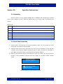
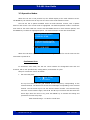
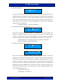
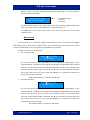

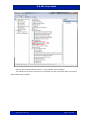
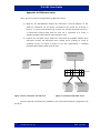
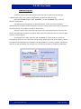
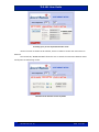
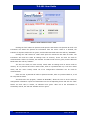
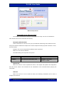
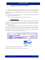
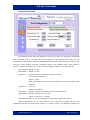
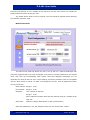
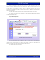
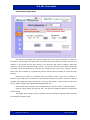
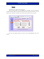
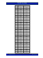
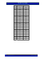

![Manual Audition 4 [By Dr.J.]](http://vs1.manualzilla.com/store/data/005935757_1-4addafd8884e379cc6f9c4cc1fe5fdba-150x150.png)