1
Exercise 1
Introduction to
MSC.Patran
Objectives:
■ Create geometry for a Beam.
■ Add Loads and Boundary Conditions.
■ Review analysis results.
MSC.Patran 301 Exercise Workbook - Release 9.0
1-1
1-2
MSC.Patran 301 Exercise Workbook - Release 9.0
Exercise 1
Geometry Model of Space Satellite
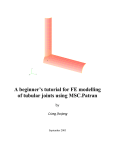
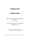
Model Description:
This exercise will take you through the steps of modeling an openended aluminum box beam that is welded to a rigid surface. It has
dimensions that are shown in the diagram below.
A downward 100-pound force will be applied, as shown. You will
determine how much the box beam will deflect, as well as the
maximum von Mises stress.
Suggested Exercise Steps:
■ Create a new database and name it as box_beam.db.
■ Create geometry.
■ Apply boundary conditions and loads.
■ Analyze model and view results.
MSC.Patran 301 Exercise Workbook - Release 9.0
1-3
Exercise Procedure:
Note: In most MSC.Patran forms, the default setting for the Auto
Execute button is on; thus, you do not need to press Apply.
Open a New
Database
1.
Create a new database and name it box_beam.db.
File/New...
New Database Name
box_beam
OK
New Model Preferences
Tolerance:
Default
Analysis Code:
MSC/PATRAN_FEA
Analysis Type:
Structural
OK
Note: If the analysis code MSC/PATRAN_FEA is not available to you,
choose another structural analysis code for which you have licenses.
If the part of the screen which was covered by the New Model
Preferences form is not redrawn, press the refresh button:
2.
A Short Word on Viewports and Groups
After pressing OK on the New Model Preferences form, you should
see a large graphics window, called the MSC.Patran Viewport (see
below).
A viewport is a window in which you view your model. You can
display more than one viewport, but to keep it simple we will be
working with only one.
1-4
MSC.Patran 301 Exercise Workbook - Release 9.0
Geometry Model of Space Satellite
Exercise 1
Viewport Name
("default_viewport")
Current Group Name
("default_group")
Database Name
("box_beam.db")
Operational Mode
("Entity or Group Mode")
The Current Viewport has a bright red border
The top of the viewport lists the name of database you are working on,
the name of the viewport, the name of the current group you are
working with, and the mode of operation for displaying the model
(Entity or Group mode).
A Group is a defined collection of geometry and/or finite element
entities. Entities, such as a surface or an element, can belong to more
than one group.
The Current Group is a specified group to which all newly created
entities will belong. You can only specify one group at a time to be the
current group for each viewport.
MSC.Patran 301 Exercise Workbook - Release 9.0
1-5
3.
Create a
Solid
Create a Solid
Though the box beam we will be creating is hollow, we will create a
solid of the box beam and later, mesh the outside surfaces of the solid.
Keep in mind the dimensions of the beam are 5 inches long with a 1
inch cross section. We will create the solid with the long direction in
the +X direction.
Geometry
Action:
Create
Object:
Solid
Method:
XYZ
Vector Coordinates List
<5, 1, 1>
Origin Coordinates List
[0, 0, 0]
Apply
For fun, rotate the model by placing the cursor in the viewport and
holding down the middle mouse button and dragging the mouse
around. Notice that when you release the button a View/Fit View is
automatically performed. You can switch from the rotate function to
translate or zoom by entering Preferences/Mouse...
4.
Change the
Viewing
Angle
Change the View Angle.
Instead of using the middle mouse button to change the view of the
model, you can use the Viewing menu, by doing the following:
Viewing/Angles...
Model Absolute
Angles
20 -10 0
Apply
Cancel
5.
Change the
Viewing
Angle
Reset the Number of Display Lines
All surfaces and faces of solids are shown with additional lines, called
Display Lines. These are not actual geometric boundaries, but they
are visualization lines to help you see the interior curvature of the
surfaces and faces.
1-6
MSC.Patran 301 Exercise Workbook - Release 9.0
Geometry Model of Space Satellite
Exercise 1
Sometimes you may need to simplify the display of your model by
lowering the number of Display Lines, and this is done as follows:
Display/Geometry
Number of Display Lines
1
Apply
Cancel
6.
Create the Displacement Boundary Conditions.
MSC.Patran has this wonderful ability to associate the loads and
boundary conditions (Loads/BCs) either with the geometry or with the
finite element model.
The Loads/BCs associated with the geometry will be applied
automatically to the nodes and elements when they are created. If you
decide later to remesh the model, the Loads/BCs will be automatically
revised. This means you can remesh your model as many times as you
wish and you won’t have to worry about reassigning the Loads/BCs to
the mesh - MSC.Patran will take care of it for you!
For our box beam model, we want to "fix" the welded end of the beam
by defining no movement in all six degrees of freedom, which is
represented by six zeroes. (A null or blank value, instead of a zero,
means the specific degree of freedom is free to move.)
To apply the fixed boundary condition:
Loads/BCs
Action:
Create
Object:
Displacement
Type:
Nodal
New Set Name
fixed
Input Data...
Translations <T1,T2,T3>
<000>
Rotations <R1 R2 R3>
<000>
Analysis Coordinate Frame
Coord 0
OK
MSC.Patran 301 Exercise Workbook - Release 9.0
1-7
Create
Boundary
Conditions
Select Application Region...
Geometry
Select Geometry Entities
At the left of the menu you should see a select menu. By default the
Geometric Entity icon is highlighted, which means MSC.Patran will
look for all geometry entities when you cursor select entities in the
viewport.
But we want to cursor select only the edges of the solid for our fixed
boundary conditions. Thus, click on the Curve or Edge icon:
Cursor select the left end edges of our solid by using a rectangular
cursor selection:
With the cursor at point “A”, hold down the
left mouse button and drag the cursor to
point “B”, so that you have drawn a
rectangular box around the left end edges of
the solid, as shown. Then, release the
mouse button.
Note: MSC.Patran highlights the selected
edges in red, and the “Select Geometry
Entities” databox will list the solid edge
IDs. (i.e., Solid 1.1.1, 1.1.2, 1.1.3, etc.).
If you are not happy with what you have
selected, you can deselect the edges by
using the right mouse button.
Finish creating the boundary condition by pressing the following
menu buttons:
Add
OK
Apply
1-8
MSC.Patran 301 Exercise Workbook - Release 9.0
Geometry Model of Space Satellite
Exercise 1
You should see light blue “cones” being drawn on the end of the solid
at the Display Lines’ point locations (shown below). These represent
the three fixed translational and the three fixed rotational boundary
conditions. Remember, these have been applied to the geometry!
7.
Apply the 100-pound Force Load.
Apply Load
Now we want to finsh our Loads/BCs by applying our 100-pound
downward force on the right corner of the solid. The force will be
defined by a vector in the global rectangular coordinate frame, where
we will have zero pounds in the +X direction, 100 pounds in the -Y
direction and zero pounds in the +Z direction.
Again, we don’t need to create the finite element mesh before applying
our force. We can associated the force with the solid.
Loads/BCs
Action:
Create
Object:
Force
Type:
Nodal
New Set Name
100_pounds_down
Input Data...
Force <F1 F2 F3>
< 0 -100 0 >
Analysis Coordinate Frame
Coord 0
MSC.Patran 301 Exercise Workbook - Release 9.0
1-9
OK
Select Application Region...
Geometry
Select Geometry Entities
Since we want to apply our force to a point on the solid, switch the
select menu icon to the Point or Vertex icon:
Cursor select the corner point of the right end of the solid, as shown:
Click on this corner of the solid with the left mouse
button. MSC.Patran will highlight the point in red.
You should see “Point 7” entered in the “Select Geometry Entities”
databox. If you cursor selected another point by mistake, press the
right mouse button to deselect it.
Finish creating the force by pressing the following menu buttons:
Add
OK
Apply
1-10
MSC.Patran 301 Exercise Workbook - Release 9.0
Geometry Model of Space Satellite
Exercise 1
Now you should see a yellow arrow drawn on the selected corner point
of the solid which is our 100-pound force:
100.0
8.
Create a New Group
Before we go on and mesh our box beam model, we want to keep our
soon-to-be finite element mesh in a group that is separate from our
geometry model.
Create a
New Group
To do this, we will created a new, empty group called “fem_model”
and make “fem_model” our current group.
Group/Create...
New Group Name
fem_model
Make Current
Group Contents:
Add Entity Selection
Entity Selection
Apply
Cancel
Note: “fem_model” has replaced “default_group” at the top of our
viewport, which means “fem_model” is our new current group.
MSC.Patran 301 Exercise Workbook - Release 9.0
1-11
Define
Mesh Seeds
9.
Define Mesh Seeds on one end of the Solid.
Before we mesh the outer surfaces of our solids, we want to take
advantage of a feature called Mesh Seeds.
Mesh Seeds allow you to define exactly how many elements (and even
what node spacing) you want on selected curves or edges of a surface
or a solid.
For our box beam model, we want to define mesh seeds of five
elements in the Y and Z directions and 15 elements in the X direction.
To do this, we do the following:.
Finite Elements
Action:
Create
Object:
Mesh Seed
Type:
Uniform
Number of Elements
Number=
5
Curve List
Because mesh seeds can only be associated with curves or with edges
of surfaces or solids, the select menu only has one icon. This means
MSC.Patran will only look for any curves or edges that you select.
Since we want to select the edges of the solid that are in the Y and Z
directions, use the rectangular cursor select box and cursor select the
edges on the left end or the right end of the solid (the illustration
below shows the solid’s right end edges being selected):
Use the rectangular cursor selection box and
select the edges on the left or right end of the
solid
Apply
1-12
MSC.Patran 301 Exercise Workbook - Release 9.0
Geometry Model of Space Satellite
Exercise 1
Now we want to create our second mesh seed for 15 elements in the X
direction:
Number of Elements
Number=
15
Curve List
Select one of the 4 edges in the middle area of the solid. The selected
edge of the solid will be red.
Apply
10.
Mesh the Outside Faces of the Solid with Quad4s
Meshing
Now we’re ready to create our finite element mesh. Though we have a
solid, we want to create a surface mesh made of 4-noded quadrilateral
elements (Quad4s). MSC.Patran allows you to create a surface mesh
on the faces of our solid.
To do this, do the following:
Finite Elements
Action:
Create
Object:
Mesh
Type:
Surface
Global Edge Length
Element Topology:
0.1
Quad4
IsoMesh
Surface List
Notice the select menu will only allow you to select surfaces or solid
faces, because the Type option on the Finite Elements form is set to
"Surface". Again, either individually select the outside solid faces
(not including the two ends) using shift/click, or:
MSC.Patran 301 Exercise Workbook - Release 9.0
1-13
you may now cursor select the faces in the middle area of the solid,
using the rectangular cursor selection box:
Use the rectangular cursor selection box and
select the edges in the middle of the solid.
Use Preferences/Picking and select Enclose
any portion of entity. The selected edges of
the solid will be red.
The Surface List databox should list "solid 1.3 1.4 1.5 1.6".
Apply
The model should now look like the following:
Equivalence
11.
Equivalence the Coincident Nodes.
You may not realize it, but duplicate or coincident nodes were created
along the edges between the neighboring solid faces. You will need to
equivalence the nodes to remove each on of the two coincident nodes.
Finite Elements
1-14
Action:
Equivalence
Object:
All
Type:
Tolerance Cube
MSC.Patran 301 Exercise Workbook - Release 9.0
Geometry Model of Space Satellite
Exercise 1
Equivalencing Tolerance
0.005
Apply
Purple circles will appear which tell you where the coincident nodes
were found and removed.
12.
Align the Element Normals.
"Why bother?", you may ask? You may not realize it, but 2-D shell
elements, like the Quad4s used in this box beam model, have a defined
top and bottom surface for results output.
Element
Normals
By default, the Quads4s we created have their positive surface normals
(which are the elements’ top surfaces) pointing in the positive global
coordinate directions. But for postprocessing the results, we want the
normals to be pointing outward from the box, regardless of their
orientation in global XYZ space.
To show you what we mean, let’s first plot the existing normal vectors
by doing the following.
First, reset the view by looking down on the end of the box beam
Click on the Right Side View icon:
Y
Z X
Now let’s plot the element normal vectors:
Finite Elements
Action:
Verify
Object:
Element
Method:
Normals
Display Control
Draw Normal Vectors
MSC.Patran 301 Exercise Workbook - Release 9.0
1-15
Make sure the Test Control icon looks like this:
It should state "Display Only" on
the side
Apply
You should see red arrows being plotted that look like this:
We want to reverse the element normal
directions on these two sides of the box
so they point outward.
Notice the normals are aligned with the +Y and +Z global coordinate
directions.
Now, let’s reverse the normal directions of the two sides indicated
above.
First, press the Display Only icon, under Test Control, so that it
changes to the Reverse Elements icon:
Changes to:
Guiding Element
Use the left mouse button and pick one element from the top surface
which is pointing in the "correct" or outward direction.
Apply
1-16
MSC.Patran 301 Exercise Workbook - Release 9.0
Geometry Model of Space Satellite
Exercise 1
You should see the element normals all pointing outward:
The normal vectors’ red arrows can be erased by either pressing the
Reset Graphics button, or by exiting the Finite Elements Application
and continuing on to the next step.
13.
Define the Material Properties.
Since the box beam is made of aluminum, we can assume the material
is isotropic and it will behave in the linear elastic region. To create the
material property:
Materials
Action:
Create
Object:
Isotropic
Method:
Manual Input
Material Name
aluminum
Input Properties...
Constitutive Model:
Linear Elastic
Elastic Modulus=
10.0e6
Poisson Ratio=
0.3
Density=
0.000259
Thermal Expand. Coeff.=
Apply
Cancel
MSC.Patran 301 Exercise Workbook - Release 9.0
1-17
Define
Material
Properties
14.
Define
Element
Properties
Define the Element Properties
Now we will define the element properties for our Quad4 elements.
The elements have a thickness of 0.05 inches and should reference the
aluminum material property that we have just created.
We will associate the element properties with the geometry model, and
not the finite elements. This will allow MSC.Patran to reassociate the
properties to the elements if we later decide to remesh the model.
First let’s reset the view to make it easier to cursor select our elements.
Press Iso 1 View icon from the toolbar:
Y
Z
X
Now let’s create our element property and reference it to our geometry
model:
Properties
Action:
Create
Dimension:
2D
Type:
Shell
Property Set Name
box_beam_shell
Option(s):
Homogenous
Standard Formulation
*
* May not be an option depending on your analysis preference.
Input Properties...
Material Name
m:aluminum
Thickness
0.05
OK
Select Members
1-18
MSC.Patran 301 Exercise Workbook - Release 9.0
Geometry Model of Space Satellite
Exercise 1
Since we want to associate our element properties with the outside
surfaces (faces) of our solid, make sure the Surface or Face icon is
highlighted in the select menu:
Now cursor select the entire model (remember our solid is still in the
group, "default_group", which is still posted (displayed) to the
viewport) Click on the Iso 1 View icon at the top to see the whole
model:
Select the entire model using the
rectangular selection box.
You should see "Solid 1.1 1.2 1.3 1.4 1.5 1.6’ appear in the databox
which are the solid face ID’s.
Add
Apply
15.
Create a Load Case
Now we want to create a load case which groups selected loads and
boundary conditions into a single set which can be referenced for the
analysis.
Load Cases
Action:
Create
Load Case Name
(load case description)
Make Current
Load Case Type:
Static
MSC.Patran 301 Exercise Workbook - Release 9.0
1-19
Create a
Load Case
Description
load_case_1
Now click on the Assign/Prioritize Loads/BCs button.
Select Loads/BCs to add to
spreadsheet
Disp_fixed
Force_100-pound_down
OK
Apply
Analyze /
Job Status /
Results
16.
Perform the Analysis / Check Status of Job / Read Results
Now we are ready to submit our finite element model for analysis.
Under Analysis, we will set up the job for the analysis and submit it
directly from MSC.Patran to MSC.Nastran.
Analysis
Action:
Analyze
Object:
Entire Model
Method:
Full Run
Job Name
box_beam_loadcase_1
Translation Parameters...
Subcase Create...
If you have time, you may
want to look at the subordinate forms for these options.
The defaults for these
options are fine for our
model.
Subcase Select...
load_case_1
Solution Type...
Direct Text Input...
OK
Apply
After pressing Apply, the heartbeat on the main form will turn blue
and you should see a number of messages scroll by in the Command
Line. The heartbeat will then turn to green which means you can
continue executing operations in MSC.Patran while the analysis is
running.
To see if MSC.Nastran has completed with no errors, open another
window and search the contents of the file, box_beam_loadcase_1.f04
in the directory where you started up MSC.Patran for the string EXIT:
1-20
MSC.Patran 301 Exercise Workbook - Release 9.0
Geometry Model of Space Satellite
Exercise 1
For UNIX, enter:
% more box_beam_loadcase1.f04 | grep EXIT
For Windows NT, enter:
% type box_beam_loadcase1.f04 | find "EXIT"
If MSC.Nastran completed with no errors, you should see the
following line:
16:23:52 0:20 20.2 0.0 11.4 0.0 SESTATIC 145 EXIT BEGN
Once the analysis has successfully completed, it will produce a
box_beam_loadcase_1.op2 results file. This file must be read into the
MSC.Patran database before you can begin to postprocess the results.
Analysis
Action:
Read Output2
Object:
Result Entities
Method:
Translate
Available Jobs
box_beam_loadcase_1
Select Results File...
Available Files
box_beam_loadcase_1.res
OK
Apply
You should see messages appear in the Command Line, stating which
results are being read into the database.
Now we are ready to postprocess the results.
17.
Unpost (Erase) the Geometry Group.
MSC.Patran 301 Exercise Workbook - Release 9.0
Unpost
Geometry
Group
1-21
Since we are done using the geometry, let’s erase or "unpost" the
group, "default_group", which contains the geometry part of our
model:
Group/Post...
Select Groups to Post
fem_model
Apply
Cancel
Notice the Loads/BCs symbols go away because they are associated
with the geometry that is part of "default_group", which is now
unposted.
Create a
Deformation
Plot
18.
Create a Deformed Shape Plot
Let’s create a deformed shape plot based on the displacement results.
This is an excellent way to view the response of our structure. Note:
The numbering of the result cases may vary.
Results
Action:
Create
Object:
Deformation
Select Result Case(s)
Select Result
1.1-DISPLACEMENTS,
TRANSLATIONAL
Apply
Although there are other ways to reset the graphics display of our
model back to the default wireframe, the easiest way is to press Reset
Graphics icon at the top before creating another postprocessing
results plot.
Create a
Fringe Plot
19.
1-22
Create a Fringe Plot of the von Mises Stresses.
MSC.Patran 301 Exercise Workbook - Release 9.0
Geometry Model of Space Satellite
Exercise 1
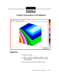
Next, let’s create a color fringe plot of our von Mises stresses.
Invariant stresses, such as von Mises stresses, are a good choice for a
fringe plot since they are scalar quantities, and they are a good
predictor of the yield stress in metals like aluminum.
Results
Action:
Create
Object:
Fringe
Select Result Case(s)
Select Fringe Result
Stress...
Quantity:
von Mises
Apply
20.
Create a Combined Fringe/Deformed Plot
Let’s create a contour plot of our membrane stresses on top of a
deformed shape plot by doing the following:
Results
Action:
Create
Object:
Deformation
Apply
Now you should see the contour plot on top of the deformed shape
plot.
21.
Modify the Finite Element Mode (Optional)
Note the high stress regions are bending stresses in the opposing
corners at the box beam’s open end (opposite of the welded end). But
they are well below aluminum’s 30 ksi yield stress.
Being the good engineer that you are, you realize the design could be
greatly improved by welding a cap on the open end of the beam.
Try posting the geometry model ("default_group") and mesh the solid
face on the open end. You can then quickly equivalence and optimize
the model and assign the existing element properties to this new area.
MSC.Patran 301 Exercise Workbook - Release 9.0
1-23
Run the model through MSC.Nastran again and see if the stress levels
improve. Good luck!
Close the
Database
and Quit
MSC.Patran
22.
Close the Database and Exit MSC.Patran.
File/Quit
Changes to your model will be automatically saved when you close
your database or exit MSC.Patran.
Congratulations and give yourself a big pat on the back!
You have just had a glimpse of the future -- the way productive people
will be doing finite element analyses from now on.
And there’s much more! Try accessing a CAD model, creating varying
loads and element or material properties through the use of Fields,
interpolating results from one analysis onto another model as loads,
and using the Finite Element Sweep mesh creation.
Examples of these and other features of MSC.Patran can be found in
Part 10: Example Problems in the MSC.Patran User’s Manual.
1-24
MSC.Patran 301 Exercise Workbook - Release 9.0