1
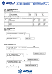
SBW SERIES
LARGE POWER FULLY-AUTOMATIC
COMPENSATION AC STABILIZER
User’s manual
1
1. INTRODUCTION................................................................................... 2
2. MODEL AND SPECIFICATION........................................................... 3
3. SERVICE CONDITION..........................................................................4
4. WORKING PRINCIPLE.........................................................................5
5. LEADING COMPONENTS...................................................................6
6. APPEARANCE AND DIMENSION......................................................9
7. USE AND MAINTENANCE..................................................................9
8. RANDOM FILE.................................................................................... 12
2
1. INTRODUCTION
SBW series three-phase high-power full-automatic compensating power voltage
stabilizers are tailor-designed for stabilizing AC current by importing and absorbing the
advanced technology from Western Europe, and conforming to the situation in our country
simultaneously. When the voltage fluctuation of outside power-supply network or the load
change causes the voltage to be fluctuated, it can automatically keep the output voltage
stable. Compared with the other stabilizers, the serial products have the advantages of
large capacity, high efficiency, no waveform distortion, stable voltage control and so on.
Furthermore, the serial stabilizers own the wide service load, the capacity for being the
momentary overload, long-term continuous operation, the switching for manual an
automatic operation, the protection against the over voltage, over current, phase shortage,
phase-sequence and the automation protection, etc, So, they are widely used in the
equipment of the large electromechanical, the metal processing, constructional
engineering, embroidery textiles, and production flow-line, electrical lift, medical apparatus
and instruments, air-conditioner, broadcast television, household appliances, lighting etc.
In the line of industry, agriculture, transportation, post and telecommunications, military
affairs, railway, scientific research culture and so on.
SBW-F Three-phase Separately-regulating Electric Voltage Stabilizer, Fully-automatic &
Compensated Type is a kind of modified SBW series product suitable for the electric
network with unbalanced three-phase voltage input. It also can balance three-phase
output automatically and keep the network operating in good condition during fluctuation
of electrified wire netting and transformation of load current.
3
2. Model and specification
1.MODEL AND MEANING
B
W
-
SERIES NO
STABILIZER RANGE
CAPACITY(KVA)
STABILIZER VOLTAGE
COMPENSATION
THREE PHASES
VOLTAGE STABILIZING RANGE:assure output voltage of stabilizer only change within
precision range
INPUT VOLTAGE:305—456V
For Example: Capacity is 100KVA, Inuput voltage range from 305V to 456V, its model
is SBW-100KVA.
2.Technology parameter and features:
model
capacity(KVA)
outputvoltage(V)
Electric current(A)
SBW-20
20
380
30
SBW-30
30
380
45
SBW-50
50
380
75
SBW-100
100
380
150
SBW-180
180
380
270
SBW-225
225
380
340
SBW-320
320
380
480
SBW-400
400
380
600
SBW-500
500
380
750
SBW-600
600
380
900
SBW-800
800
380
1200
SBW-1000
1000
380
1500
4
a. Input voltage:
Type1: 380 ±20%;
Type2: Single phase 220V ± 20%.
b. Voltage regulator accuracy: <2%, (adjustable from 1% to 4%)
c. Response time<1.5s
d. Output voltage: three phase 380V
e. Frequency: 50 HZ
f. No wave distortion
g.No output voltage and phase shift;
h. The adjustment of voltage is placidity, no phenomenon of instant power
off.
i. Can support instant overload
j. Automatic restart (option)
k. Fault phase and lack phase protection
3. SERVICE CONDITION
Normal service condition of SBW series stabilizer in door is following:
1.Operating temperature: 0℃_40℃;
2.Comparative temperature:Rh90% 25℃;
3.Altitude:<1000 meter;
4.There is no strict gas,vapour, chemical sediment, dirt and other blasting and
eroding medium which affects stabilizer in the built-in location.
5.There is no strict libration and Jounce in the built-in location
6.User should negotiate with us when is not in accordance with above particular
conditions.
4. Work principle
The stabilizer is made up by compensation circuit, control circuit, servo system and
control loop. The electric principle please refers to figure 1:
5
CJ1
CJ2
A
Input
CJ3
Compensation
B
B
circuit
C
C
N
N
Contact circuit
A
Serve system
Voltage
detect
Output
Protection
circuit
figure 1、The figure of SBW principle
Voltage compensation principle please refers to figure 2. Contact booster B and
compensation transformer C, the booster is connected to the output port of the
stabilizer makes it up, and the compensation transformer is series connected in main
loop.
The impedance of compensation transformer is:
U2=U1+UC
Uai- input phase voltage
Uao- output phase voltage
Uac- Phase comprehension voltage
When the input voltage Uai change Uai, the compensation voltage Uai changes Δuac,
and Uac=Δuai, output voltage Uao will hold the line this time. The change of Uac is
based on output voltage, due to the voltage check cell output signal, and then
through organ to control servomotor running, and drive the electric brush on booster
to slip. The output voltage of the booster to change the compensation voltage to
automatically carry out the stabilization of output voltage.
5. LEADING COMPONENTS
1. Compensation transformer
6
In fact, compensation transformer is a set of three-phase transformer, which can
change voltage.
2. Contact booster
Contact booster is a set of single or three phase autotransformer, which can
self-regulation output voltage. The servo motor drive the brush along the
autotransformer slips on the surface, and adjust the output voltage placidly.
3. Controlling circuit
Controlling circuit contains voltage check, servo motor control and protection circuit.
About the detail course of protection please refer to figure3:
Air switch brake
Phase order is right
or no lack phase?
N
When JO is off, loop will be
shut off. If has started-up, the
stabilizer will be off.
N
Y
N
Press ON key?
Y
Y
Voltage regulator
N
is normal
If the time
exceed 4S?
Y
No over voltage
and lack phase?
If contact
the switch?
Y
With motor
signal?
Y
N
Y
If the drive
time exceed
4S?
N
7
Figure3 is sketch map of Protection function
When users need to adjust relative parameter, about the control veneer please
refers to figure 4:
W0: Adjustor of voltage regulator
W1: Warning adjustor of over-voltage
W2: Adjustor of positive error accuracy
W3: Adjustor of negative error accuracy
W4: Adjustor of lack voltage
W5: Adjustor of alarm
Figure 4: control
K0: Auto and manual switch
board(over100KVA)
K1: The manual switch of increasing voltage
K2: The manual switch of decreasing voltage
When you need adjust output voltage, please loose the locknut of W0, then move
the slowly. Circumgyrate output voltage will fall, contrarotate the output voltage will
hoist. When adjust to full, screw down the locknut.
W2 and W3 is voltage regulator precision setting equipment. Adjust it <2% when
leave factory. Normally, you had better not adjust the two equipments. When voltage
fluctuates frequently, influence the brush run frequently, or the booster appears
surge, you can circumgyrate the W2 and W3 to clockwise a little. Then the voltage is
about ±4%。
W1 and W4 is over voltage and lack voltage adjust switch, we adjust it at +8% when
leave factory, normally, the two switches don’t need to adjust.
K0 is automatic and manual switch. We have adjusted it at automatic situation when
leave factory. When K0 is in manual mode, press K1 and K2, the highness and
lowness of the output voltage is adjustable. Please pay attention that the two switch
are used in the condition when debug the stabilizer or necessary. K0 must park at
automatic place when the stabilizer is running.
J0 is protection relay, when press start button QA2 is inefficacy (normally press QA2,
the stabilizer will start after minutes). You have to check if lack phase or phase
number is wrong. Normally, J0 is in shut down mode (when green LED is not off,) this
can prove that the trouble is due to over voltage, lack voltage or servo motor
8
protection. If J0 is replacement at that time, restart is ok,
4. Main circuit switch and operation circuit
An air switch K2 and three AC contact units CJ1, CJ2 and CJ3 are setted up on the
circuit of the stabilizer. CJ2 and CJ3 are setted up for auto compensation system
convenient devotion and exit. Devotion called voltage regulator function. The
devotion of CJ1 we call it straight function. CJ2 can carry out closedown function
among CJ1, CJ2 and CJ3, in order to prevent the three ones shut off at one time.
Main circuit switch: CJ1, CJ2 and Cj3 is in series. CJ2 and CJ3 connected with CJ1,
carry out the closedown. So the stabilizer can transform from one mode to another,
and have no phenomena of shut down.
In loop of the contact equipment, connect a touch spot J0-1 to protect relay J0. After
the stabilizer closing K2, J0 will shut, and then can operate the circuit. When the
stabilizer appears trouble, protection relay will run, let the loop of voltage regulator
exit. At the same time, series connected a self-check protection relay and protection
relay, as long as appears lack phase and wrong phase number, the loop shouldn’t
shut down. But the voltage regulator can be operated when there is no lack phase
and no phase order mistake
6. Appearance and dimension
Appearance
Capacity
KVA
SBW-F
Single cabinet
Double cabinet
Dimension
30
800*500*1500
100
900*600*1600
180
1000*700*1750
225
1050*750*1800
320
1100*800*1950
400
1100*850*1950
500-600
1000*600*2200
Attention: if it is double cabinet, the length should * 2.
7. Use and maintenance
1. Check before power on
9
(1) No damage in every part of stabilizer, stable and reliable firmware
(2) The coils between electronic brush and AVR touch each other well, no lack and
damage on electric brush
(3) Conformity between power voltage and AVR
(4) The insulation resistance value≥3megohm
2.Connection
(1) Power must be connected to the input end of AVR, and to the output end for load,
neutral line is connected to the junction strip under the AVR or on insulating port.
The outer case must be connected to the ground
(2) Use the proper cable consistent to AVR’s power and connect air switch though
current mutual inductor. stabilizer above SBW-100 will be rolled with only one circle
(200/5 current mutual inductor: stabilizer below SBW-50 should be rolled with two
circles (100/5,75/5,50/5 current mutual inductor),otherwise the there will be
incorrect indication on current watch
3.Check order of connecting electric
a. Power on after checking all above and right connecting,connect the switch K2, the
power indicator light will be on, if press QA1, the indicator on voltage watch should
be consistent with input voltage watch.
b. Let it drive into auto compensation system by pressing key QA2, regulator light LO
will be on, if press start button QA2, AVR will work after several seconds, and output
voltage will be self-regulation to regulator accuracy range.
c. Regulator accuracy and voltage adjusting has been adjusted well before leaving
factory, if need adjusting, please refer to”4”.
4. Use notice
⑴ have to know the stabilizer the use condition before using
⑵ The load current should not exceed the fixed current value.
⑶ if the input voltage is normal, but output voltage is unstable, should check in
time( please refer to the disposal of faults).If input voltage exceeds the permitted
range, but the output voltage has little influence to user, you can continue to use.
When input voltage recovers normal, the output voltage can remain stability
automatically.
⑷ special power can tailor-order to our company
⒌ The disposal of troubles
⑴ output voltage departures the permitted data badly.
a. If the switch Ko is setted up in Auto position
b. If input voltage oversteps the permitted range.
10
c. Auto/manual switch K0 is setted up in” manual” position, then press K1 and K2,
see if the brush move on sideway normally.
⑵ Output voltage departures the fixed value a little.
a. Adjustor W0 can adjust output voltage to needed stable value.
b. Adjustor W2 and W3,can let the departure of the accuracy within permitted range
⑶The stabilizer surge of output voltage
This because the accuracy is too high and doesn’t match the slip speed of the brush.
You can circumgyrate the W2 and W3 to clockwise a little and debase the accuracy,
so the surge may disappear.
⒍ Maintenance
According to different use environment, so the maintenance cycle is different, but
the cycle shouldn’t over six months, and the main maintenance including:
⑴Clear all the dust and dirt of the Stabilizer, especially brush, contact adjustor, brush
slipway and drive parts. You have to use benzine and sponge to clear when
necessary.
⑵Change the brush in time when it is damaged
⑶Repair and change the fault and damaged parts in time
⑷After using about 2 to 3 months, had better to adjust the degree of tightness of all
the parts.
7. Attachment
SBW Three-phase Electric Voltage Stabilizer, Fully-automatic & Compensated Type is
a kind of modified SBW series, and mostly below 100KVA.Absolutely solve some
avoidless faults, for example, unbalance of the three phases let the equipment can’t
work normally. For user, well adapts various and unbalance load, Base on the three
phase is Separately-regulating, we can adjust each phase to meet users’
requirements.
SBW Three-phase Electric Voltage Stabilizer is also modified on operation, when shut
off the chief power switch and no lack phase and wrong phase, the stabilizer can run
automatically. When user need regulator, please press “regulator” button on the
front board, and then it can drive into regulator state. When power itself has faults,
but output voltage is still in normal use range, the stabilizer can exit automatically
this time, then shift to straight function, make sure the equipment can run normal.
When regulator loop of the power gets right, Please press” recover” button, then can
drive into regulator state afresh.
SBW-F Three-phase Separately-regulating Electric Voltage Stabilizer adopts the
advanced mature circuit of PANASONIC, at the same time, at key parts of brush,
11
adopts the patent product, prolong the use life of and stabilizer and enlarge the
regulator range.
So large regulator range (280V to 456V) can make sure various
loads can run normally.
8. RANDOM FILE
1.USER’S MANUAL
2.Products Warranty Card
12