1
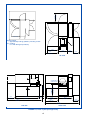
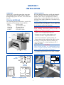
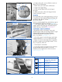
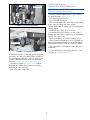
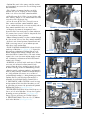
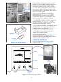
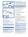
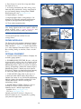
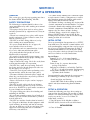
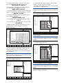
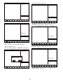
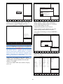
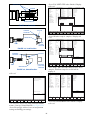
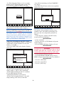
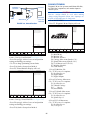
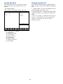
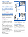
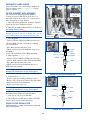
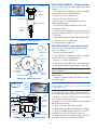
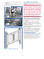
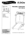
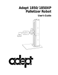
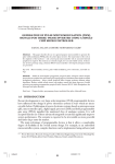
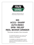
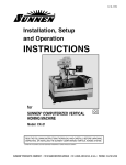
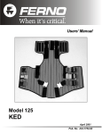
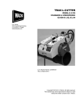
PNEUMATIC LINES CHECK
SHUT-OFF
VALVE
Inspect Pneumatic Lines and Fittings monthly for
leaks or damaged parts (see Figure 4-4). Replace
parts as required.
FILTER ELEMENT REPLACEMENT
AIR SOLENOID
VALVES
Filter Element in airline Regulator should be
cleaned or replaced annually or when there is a
noticeable drop in air pressure. To clean or replace
Filter Element proceed as follows:
1. Turn OFF power to Machine at Master ON/OFF
Switch on Electrical Control Enclosure.
2. Shut OFF air supply at Shut-Off Valve or disconnect
In-Coming Factory airline.
MIST
SEPARATOR
CAUTION
Plunger is held in Unit by a Spring. Use care in
disassembling to prevent Spring from being lost.
FILTER
REGULATOR
3. Filter Regulator (see Figure 4-5):
• Unscrew Threaded Bowl from Body and lay aside.
• Remove Baffle and Filter Element by removing
Screw and Washer.
• Wipe Bowl and internal parts clean.
• Install new Filter Element and Baffle using Screw
and Washer.
•Screw Threaded Bowl, with O-Ring onto Body.
4. Mist Separator (see Figure 4-6):
• Unscrew Threaded Bowl from Body and lay aside.
• Unscrew Baffle and and remove Element from Shaft.
• Wipe Bowl and internal parts clean.
• Install new Filter Element on Shaft; then screw
Baffle onto end of Shaft.
SHUT-OFF
VALVE
AMBIENT
DRYER
FIGURE 4-4, Pneumatics
BODY
O-RING
BAFFLE
FILTER
ELEMENT
WASHER
SCREW
BOWL
NOTE: Replacement Elements and parts are available
through Unit manufacturer or your local supplier.
• Screw Bowl, with O-Ring, on Body and firmly tighten.
5. Ambient Dryer (see Figure 4-7):
• Remove Capscrews holding Housing in place.
• Remove Filter Element by unscrewing from Shaft.
• Install new Filter Element on Shaft.
• Replace bowl and capscrews.
NOTE: Replacement Elements and parts are available
through Unit manufacturer or your local supplier.
FIGURE 4-5, Airline Filter/Regulator
BODY
SHAFT
6. Turn ON air supply at Shut-Off Valve or reconnect
In-Coming Factory airline at Quick-Disconnect.
7. Close top access Cover to Machine.
8. Turn ON power to Machine at Master ON/OFF
Switch, on Electrical Control Enclosure.
ELEMENT
O-RING
BOWL
DRAIN FILTER REGULATOR
All filtering units are equipped with automatic drains and
pumped to the ground.
FIGURE 4-6, Mist Separator
30