1
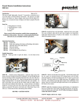
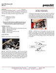
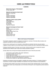
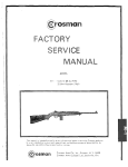
The QB78 CO2 Pellet Rifle
A User’s Manual Text, photos and illustrations by George Fox Lang
An introduction to using the classic QB78 pellet rifle, one of the nicest and most popular CO2
rifles ever produced. The QB78 is a svelte sculpture in steel and hardwood sold at a bargain
price. It provides low-priced entry to the world of precision airguns and unending opportunities for
the adventurous experimenter.
© George Fox Lang, 2006 – All Rights Reserved
Neither this manual nor any of its content may be
reproduced or copied, for any commercial purpose,
without the written consent of the author.
Distributed exclusively by
Flying Dragon Air Rifles
About the QB78
The QB78 is a modern classic manufactured by the Shanghai Air Gun factory and sold worldwide under
the Industry brand. It is a compact and handsome CO2-powered rifle made of blued-steel and hardwood. It
is a manly weapon with nothing “toy-like” or plastic about it. The QB78 exhibits power and accuracy
matching its good looks. It was patterned after the no longer manufactured Crosman 160 and 167 airguns.
SPECIFICATIONS
Type: single-shot, bolt action
Caliber: .177 (4.5 mm) or .22 (5.5 mm)
Muzzle Velocity: 600 FPS (.177) or 420 FPS (.22) typical within 60° to 80°F
Accuracy: 0.5 inch center-to-center at 10 yards typical
Trigger: Single-stage; adjustable for tension, over travel, sear engagement
Sights: open iron sights; rear adjustable for elevation; 17.5” sight radius
Barrel: 21.4 inch (543 mm), target grade steel
Energy Source: two 12-gram CO2 Powerlet® cartridges
Stored Energy: typically sufficient for 50-60 full-power shots
Length Overall: 40 inch (1015 mm)
Length of Pull: 14 in (355 mm)
Weight: 5.75 lb (2.6 kg)
Powerlet is a registered trademark of the Crosman Corporation
Setup
Before using your new rifle, inspect it carefully to assure that all parts and accessories are present and that
no shipping damage has occurred. Retain the shipping container and packing, in the event that subsequent
service is required.
Be certain the rifle is unloaded, before doing anything else! Check to see that the bore is unobstructed. Be
certain the gas tube cap can be turned by hand. Verify the bolt, trigger and safety functions.
2
Operation - Installing CO2 Cartridges
1.
Verify that the Gas Tube Cap can be
loosened by hand, as shown above. Never
use a tool to rotate this cap. A tight cap
indicates dangerously high gas pressure
remains within the Gas Tube.
2.
Apply the Safety by swinging it to the rear
as shown above.
3
3.
Open the Bolt as illustrated above. Opening
the bolt leaves the loading chamber open to
inspection. More importantly, retracting the
bolt prevents dangerous accidental piercing
of the rearward-facing CO2 cartridge.
4.
Unscrew the Gas Tube Cap from the Gas
Tube and set it aside. Slide two 12-gram
CO2 cartridges into the Gas Tube back-toback as shown above. Note, for shorter
shooting sessions, load an empty cartridge as
the rearward-facing (first installed)
cartridge. This will give approximately 30
full-power shots.
5.
Screw the Gas Tube Cap back on fully; this
will pierce the forward-facing CO2 cylinder.
When the cap has seated fully hand-tight,
back it off a quarter-turn. This will allow the
CO2 to flood the Gas Tube. Do not forget to
back off or the forward-facing cartridge will
remain sealed by the Gas Tube Cap.
6.
Check that the chamber is clear.
Operation - Shooting
Basic operation of the rifle is very simple. To
fire a pellet:
7.
8.
9.
1.
Lift the Bolt Handle and pull it fully to the
rear to open the breech.
2.
Insert a pellet of the proper caliber into the
open breech. Make certain the pellet enters
nose-first with the fan-tail skirt to the rear,
as shown.
3.
Push the Bolt Handle fully forward and
rotate it down. This seats the pellet into the
rifling and seals the breech. The weapon is
ready to fire.
4.
Aim at your target, place your trigger finger
within the Trigger Guard and squeeze the
Trigger gently.
Close the Bolt, cocking the rifle.
Release the Safety, by rotating forward and
out of the trigger guard.
Point the rifle in a safe direction and pull
the trigger. A mild report ‘pop’ verifies the
weapon is now charged with CO2 and is
ready for shooting.
4
Trigger Adjustments
2.
Unscrew the Locating Screw Nut and
remove the action from the stock.
3.
Use a #2 Phillips-head screwdriver to
remove the two Casing Plate Screws. Lift
off the Casing Plate to expose the trigger
mechanism.
4.
Use a 2 mm flat jeweler’s screwdriver to
adjust the Sear Engagement and
Overtravel screws. Use a 3/16” flat
screwdriver to adjust the Tension screw.
5.
Reassemble the rifle by following these
instructions in reverse sequence.
The QB78 trigger features three adjustments:
A – Tension or trigger force
factory set to about 4 lbs
turn screw counter-clockwise to reduce
Setting tension below 2 lbs may result in
accidental discharge if the rifle is dropped.
B – Over travel or backlash
factory set to about 0.25”
turn screw clockwise to reduce
Turning screw too far clockwise will prevent the
rifle from firing.
C – Sear Engagement or pull length
factory set at about 0.125”
turn screw clockwise to reduce
Reduced sear engagement may result in
accidental discharge if the rifle is dropped.
To Make Trigger Adjustments
Unload the rifle before making adjustments.
1.
Place the Safety lever in the SAFE position
and push it out of the Trigger Casing from
left-to-right. Use the eraser-end of a wooden
pencil as the dismounting tool.
5
Mounting a Scope
One of the most popular options for any airgun is
a telescopic sight. The QB78 is an accurate rifle
and it fully deserves a good quality optical sight.
If possible, choose a scope with an Adjustable
Objective (AO). This is a second focusing
adjustment, allowing the scope to be used at
close distance (10 yards or less). (The first
focusing adjustment is for the eyepiece and it
compensates for your eye.)
Your QB78 has receiver grooves that will accept
‘standard’ 11 mm airgun or airgun/rimfire rings.
(Note that these are different from Weaver mount
rings.) For best results, use the lowest saddle
height rings possible. This keeps the scope axis
as close to the bore axis as possible.
1.
Prepare the rings for application. If they
contain recoil stop-pins, remove them as the
QB78 has no mating stop-pin holes. Remove
the caps from the ring bases.
2.
Mount the bases to the receiver. Only handtighten the clamp screws; you need the bases
to slide freely at this point.
6
3.
Fit the scope into the bases. Slide one of the
bases until the spacing is ‘right’ about the
scope’s central turret. Add the ring caps, but
only hand-tighten their screws.
4.
Hold the rifle in firing posture. Slide the
scope back and forth until you achieve a
position that lets you see through the optic
with the least “tunnel vision”. Lock the base
screws at this location. Twist the scope body
to align the graticule vertical line up and
down. Then tighten the cap screws.
Optical Adjustments
5.
If necessary, use a #2 Phillips screwdriver to
remove the two screws securing the rear
iron-sight. Save these pieces for future use.
1.
6.
7.
Install scope accessories such as filters, sunshades, and lens caps.
Note: when fitting a short or ‘mini’ length scope,
(such as the Leapers 6x32 Bugbuster illustrated)
you may have to compromise this position to
leave the breech clear of the scope’s front bell.
If desired, use a 1/8” flat-bladed
screwdriver to remove the front sight.
2.
Focus the eyepiece or ocular adjustment to
provide a crisply defined graticule. Viewing
an uncluttered target such as a light-colored
painted wall makes this adjustment simplest.
3.
Set up a target at the desired shooting
distance. Focus the front-bell (or side-wheel)
parallax adjustment to provide a clear image
of the target.
When both the graticule and the target are in
sharp focus, the two images are in the same
plane within the scope. This allows your eye
position to move without affecting the point of
aim.
4.
8.
Physically position the scope fore-and-aft
from your eye. When properly positioned,
the scope will present a full field of view,
free of “tunnel vision”. Your eye is now
within the eye relief of the scope.
Adjust the windage and elevation of the
scope to force the point-of-impact to
converge with the point-of-aim. Do this as
an iterative process, starting at close range
and incrementally moving back to your
desired target range.
Use care not to over-torque the small base and
cap mounting screws provided with your scope
rings. Only hold the short side of your Allen
wrench when tightening scope screws.
Zero the scope to the rifle by firing from a
steady rest. Start at a close distance and
work out.
7
Theory of Operation
The following figures are not scale drawings of the QB78 parts; they are schematic diagrams intended to
explain how the rifle functions. Some artistic liberties have been taken for clarity of explanation.
ARRANGEMENT OF PARTS
The Breech Tube (1) contains the Bolt (2) and is attached to the Barrel (3) by a setscrew and O-rings. It
sits atop the Gas Tube (4) to which it is screwed. An O-ring seals a gas transfer path between the Valve
Body (8) contained in the Gas Tube and the firing chamber sealed by an O-ring on the Bolt.
The Gas Tube (4) holds two CO2 cartridges (5) back-to-back. The reward-facing cartridge is in front of
the Piercing Pin (6), the Valve Stem (7) and the Valve Seat (8). A Valve Spring (9) surrounds the
Piercing Pin and reacts against it and a fixed spacer.
The rear of the Gas Tube houses the Hammer (10) and Cocking Piece (11). These parts are surrounded by
the Hammer Spring (12), which reacts against both of them. Note that pins are fitted to the Hammer and
Cocking Piece. These pins connect these parts mechanically with the Bolt, through facing slots in the
Breech Tube and the Gas Tube.
The spring supported Sear (13) protrudes into the Gas Tube from the Trigger Casing Assembly, screwmounted to the bottom of the Gas Tube. The sear is a cam-like device that can hold the Hammer in a
rearward position until the Trigger causes it to fall away.
As shown above, the rifle has been fired and the bolt remains closed on an empty chamber. Both the
Hammer Spring and the Valve Spring are in their relaxed (but preloaded) conditions. CO2 gas fills the
front portion of the Gas Tube but is blocked from further infiltration by the Valve Stem pressed firmly
against Valve Seat by the Valve Spring. The Hammer rests upon the Valve Stem in this equilibrium.
OPENING THE BOLT
Raising its handle and pulling the Bolt (2) to the rear moves the Hammer rearward through action of the
Hammer Pin. The modest compressive preload of the Hammer Spring is retained against the bolt through
the Cocking Piece Pin. With the Bolt open, a pellet can be placed in the mouth of the firing chamber.
8
CLOSING THE BOLT
Pushing the Bolt forward (and lowering its handle) cocks the weapon and locks the pellet in the firing
chamber, ahead of the gas transfer port. The pellet is forced into the Barrel’s twisted grooves and the Oring on the Bolt seals the chamber behind it. As the Bolt moves forward, the Hammer and Cocking Piece
follow it. Forward motion of the Hammer is arrested by the Sear, which stops the Hammer about 7/16”
before it can contact the Valve Stem. The Cocking Piece moves forward about an inch, compressing the
Hammer Spring. The rifle is now ready to fire.
FIRING THE RIFLE
Squeezing the Trigger causes the Sear to fall, allowing the Hammer to move forward rapidly under
pressure of the Hammer Spring. The Hammer impacts the Valve Stem and is then arrested by a stop
spacer and the back of the Valve Seat. The Valve Stem continues forward, opening the Valve Seat and
transfer port to an inrush of CO2 gas. The Valve Stem continues its forward travel, driving the Piercing
Pin forward and compressing the Valve Spring. The pellet is launched by the released gas and starts its
journey, spinning down the Barrel. The Piercing Pin is driven into the welded seal of the rearward-facing
CO2 cartridge, piercing it (if it is still sealed). Note that the foreward-facing CO2 cartridge is pierced during
loading, by a separate piercing pin in the tube cap.
A FEW MILLISECONDS AFTER FIRING
The compressed Valve Spring eventually extracts the Piercing Piece from the CO2 cartridge and presses it
back against the Valve Stem, which is forced back against the Valve Seat. This stops the flow of gas just
as the pellet is about to exit the Barrel and the starting conditions are reestablished.
9
About CO2
Your QB78 rifle uses two common 12-gram
Powerlet® CO2 cartridges. This is sufficient
energy for about 60 full-power shots if used
within a temperature range of about 60 to 80 °F.
100
90
Liquid
80
Percent Mass
70
The Powerlet wraps 31.5 grams of deep-drawn
steel around 12 grams of liquid and gaseous
carbon dioxide (CO2), locking it in a
hermetically sealed vault with a minimum burstpressure of 7000 pounds per square inch (psi)
pressure. The bottle is smooth and seamless,
providing a precisely controlled 14 cc volume
sealed by a pierceable steel plug welded to the
bottle’s neck.
60
50
40
30
20
Gas
10
0
0
20
40
60
80
100
120
140
160
Temperature (° F)
The critical temperature of CO2 is 87.8° F and
this temperature is of particular importance to
air-gunners. As shown in the graph above, below
this temperature both gas and liquid CO2 coexist
in the Powerlet. Above this temperature, only
gas can be present. The cartridge exhibits a
natural pressure-regulating mechanism, but only
at temperatures lower than 87.8° F.
SECTIONED VIEW OF A POWERLET
At low temperature, the bulk of the entrained
CO2 is in liquid state. As the ambient
temperature rises, heat enters the cartridge and
some of the liquid boils to gas; the percentage of
gas in the mixture increases, as does the
pressure. Below 87.8° F, the boiling stops when
the pressure reaches the vapor pressure
determined by the ambient temperature as long
as some liquid remains. Above this critical
temperature, all the CO2 boils to gas.
The Powerlet contains a considerable amount of
energy (over 280 ft-lb or 380 Joule). This is
approximately equivalent to two high-velocity
.22 long-rifle shells, or one .38 Special (+P)
cartridge. To place this in another perspective,
the contained energy is sufficient to light a 100Watt bulb for nearly four seconds. Any one of
these equivalents is clearly capable of injuring
you; the CO2 cartridge must be treated with care
and respect!
When a shot is made, some CO2 gas exits the
cartridge rapidly and the ratio of gas-to-liquid is
instantaneously reduced. The loss of gas reduces
the pressure within the cartridge, causing some
of the liquid to boil or vaporize to “fill the void”.
This vaporization extracts heat from the mixture,
cooling it.
When used near room temperature, it is capable
of delivering most of this stored energy as useful
muzzle energy. Fifty (slow fired) shots of 600
foot per second (fps) velocity with a 7.1 grain
pellet (5.7 ft-lb muzzle energy) is a reasonable
expectation.
The mixture continues to boil liquid to gas,
increasing the pressure while drawing heat from
the ambient temperature surroundings.
Eventually, the mixture warms back to the
ambient temperature and the boiling stops when
the pressure reaches the vapor pressure. Hence
the next shot will be made from exactly the same
pressure source. This is the natural pressureregulation mechanism provided by CO2.
If the firing pace is slow and deliberate, these
shots will exhibit remarkably consistent velocity,
owing to the “built-in pressure regulation”,
provided by thermodynamic interplay between
the liquid and gas phases of CO2.
Powerlet is a registered trademark of Crosman Corporation
10
When the cartridge is nearly depleted, the
transition point marks the end of useful life. This
is the point at which all of the liquid CO2 has
been consumed.
Consider what happens when a mass of CO2 is
sealed in a fixed-volume container. If the massto-volume charge density is equal to the 0.468
g/cc critical density, the pressure within the
container will exactly equal the vapor pressure
for any temperature below the 87.8° F critical
temperature. If a larger (or smaller mass) of CO2
is present, the pressure-versus-temperature line
will depart from the saturation line at a
temperature below 87.8° F, as shown below.
Re-plotting this data with a different format
makes the natural regulation process more
evident. The following plot presents a family of
pressure-versus-mass lines, each for a different
ambient temperature. Note the broad constantpressure (horizontal) segment in each line below
the (dotted) 87.8° F curve.
CO2 Rem aining
6000
12
5000
4000
10
3000
Pressure (psig)
Pressure (psig)
11
8
6
2000
4
2
1000
1
0
0
20
40
60
80
100
120
140
160
Temperature (° F)
Tem perature (° F)
1500
1400
1300
1200
1100
1000
900
800
700
600
500
400
300
200
100
0
100
90 80 70
60
50
40
30
20
0
1
2
3
4
5
6
7
8
9
10
11
12
Co2 Remaining in 12-gram Powerlet (g)
This figure presents the pressure within a
Powerlet as a function of temperature with from
1 to 12 grams of CO2 remaining in the bottle.
Note the blue segment partially common to all of
these traces; this is the saturation line. A CO2
charge of 6.55 grams remaining in the 14 cc
cartridge volume (0.468 g/cc) will exhibit a
pressure-versus-temperature curve that follows
the saturation line all the way to 87.8° F; all
other charges depart from the blue line at a lower
temperature.
CO2 regulation is summarized below. Mark the
ambient temperature on the horizontal scale and
read the corresponding pressure and mass limits
directly above it. For example, on a 70° F day, a
regulated pressure of 840 psig will be provided
as long as the Powerlet holds at least 2.8 grams
but not more than 10.6 grams of CO2. Hence the
first few shots will be “hot” until you use 1.4
grams from a new Powerlet. You will “run out of
liquid” when 2.8 grams of gas remain in the
cartridge.
The point of departure from the blue segment is
termed the transition point, defining a transition
temperature and a transition pressure. Above the
transition temperature, the CO2 behaves as a gas
with pressure rising with increasing temperature.
When the Powerlet is essentially full, the slope
above the transition point is very steep and
pressure rises rapidly with temperature to
potentially dangerous levels.
13
12
11
10
9
8
7
6
5
4
3
2
1
0
M aximum C O 2 f o r
R eg ul at ed Pr essur e
M inimum C O 2 f o r
40 45 50 55 60 65 70 75 80 85 90
Tem perature (° F)
11