1
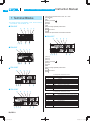
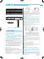
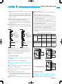
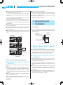
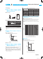
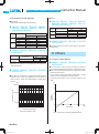
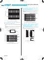
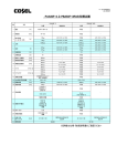
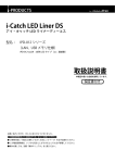
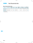
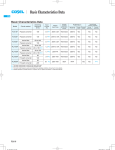
Basic Characteristics Data
PBA/PBW
PBA/PBW
Basic Characteristics Data
Model
Circuit method
Switching
frequency
[kHz]
Input
current
[A]
PBA10F
Flyback converter
100
0.3
PBA15F
Flyback converter
100
0.4
PBA30F
Flyback converter
100
0.7
PBA50F
PBA75F
Active filter
60 - 550
Forward converter
130
Active filter
60 - 550
Forward converter
120
0.7
Material
Single
sided
Series/Parallel
operation availability
Double Series Parallel
sided operation operation
LF
CEM-3
Yes
Yes
*1
Thermistor
CEM-3
Yes
Yes
*1
250V 3.15A Thermistor
CEM-3
Yes
Yes
*1
Thermistor
CEM-3
Yes
Yes
*1
Thermistor
CEM-3
Yes
Yes
*1
Thermistor
CEM-3
Yes
Yes
*1
Yes
Yes
*1
Rated
input fuse
250V 2.5A
250V 2A
1.0
Inrush
current
protection
circuit
PCB/Pattern
250V 3.15A
Active filter
60 - 550
Forward converter
120
Active filter
60 - 550
Forward converter
120
Active filter
230
Forward converter
330
Active filter
130
Forward converter
330
Active filter
130
Forward converter
280
Active filter
130
Forward converter
200
Active filter
130
Forward converter
200
PBW15F
Flyback converter
100
0.4
250V 2.5A Thermistor
CEM-3
PBW30F
Flyback converter
100
0.7
250V 3.15A Thermistor
CEM-3
Active filter
60 - 550
Forward converter
130
CEM-3
PBA100F
PBA150F
PBA300F
PBA600F
PBA1000F
PBA1500F
PBA1500T
PBW50F
1.3
2.0
250V 4A
Thermistor
CEM-3
4.1
250V 10A
SCR
FR-4
Yes
Yes
Yes
8.2
250V 15A
SCR
FR-4
Yes
Yes
Yes
SCR
FR-4
Yes
Yes
Yes
SCR
FR-4
Yes
Yes
Yes
SCR
FR-4
Yes
Yes
Yes
Yes
Yes
*1
Yes
Yes
*1
Yes
Yes
*1
13
250V 30A
19
6
0.7
250V 16A
250V 2A
Thermistor
*1 Refer to Series/Parallel Operation of Instruction Manual.
* The value of input current is at ACIN 100V and rated load, ACIN 200V 3f and rated load in PBA1500T.
PBA/PBW-32
PBA/PBW-32
PB_E.indd 32
15.6.18 5:48:04 PM
AC-DC Power Supplies Enclosed Type Instruction Manual
PBA/PBW
1
Terminal Blocks
PBA/PBW-34
2
Functions
PBA/PBW-35
2.1
Input Voltage Range
PBA/PBW-35
2.2
Inrush Current Limiting
PBA/PBW-35
2.3
Overcurrent Protection
PBA/PBW-36
2.4
Overvoltage Protection
PBA/PBW-36
2.5
Thermal Protection
PBA/PBW-36
2.6
Output Voltage Adjustment
PBA/PBW-36
2.7
Remote ON/OFF
PBA/PBW-37
2.8
Remote Sensing
PBA/PBW-37
2.9
Alarms
PBA/PBW-38
3
Peak Current
PBA/PBW-39
4
Series/Parallel Operation
PBA/PBW-39
5
6
7
4.1
Series Operation
PBA/PBW-39
4.2
Parallel Operation/Master-slave Operation
PBA/PBW-39
4.3
N+1 Parallel Redundancy Operation
PBA/PBW-40
Assembling and Installation
PBA/PBW-40
5.1
Installation
PBA/PBW-40
5.2
Derating
PBA/PBW-41
5.3
Expected Life and Warranty
PBA/PBW-42
Others
PBA/PBW-42
6.1
Output Current Monitor
PBA/PBW-42
6.2
External Capacity
PBA/PBW-43
6.3
Isolation
PBA/PBW-43
6.4
Auxiliary Power
PBA/PBW-43
6.5
External Component (EMI/EMC Filter)
PBA/PBW-43
Options
7.1
Outline of Options
PBA/PBW-43
PBA/PBW-43
PBA/PBW-33
AC-DC Power Supplies Enclosed Type
PBA/PBW
1 Terminal Blocks
*The following information covers PBA300F - 1500F. Please see External
View for PBA10F - 150F and PBW15F - 50F.
¿ PBA300F
å
0
9
7
8
Instruction Manual
1AC (L) Input Terminals AC85 - 264V f47 - 63Hz
2AC (N) (M4)
3NC
4Frame ground (M4 )
5-Output
6+Output
7LED
8Output voltage adjustable potentiometer
9CN1
0CN2 Connectors
åCN3
*Please see Optional Parts for dedicated harnesses.
H
V. ADJ
¿ PBA1500T
0
å
1 2 4
5
9
8
7
6
V.ADJ
¿ PBA600F
(L1)
AC
(L2)
CN1
(L3)
FG
CN2
0
å
9
7
8
CN3
1 2 3 4
CN3
AC
( L)
CN2
5
6
¿ PBA1000F
0
å
9
8
7
H
V. ADJ
AC
(L)
AC
(N)
CN1
FG
CN2
CN3
1 2 4
5
6
¿ PBA1500F
0
å
9
8
AC
( N)
CN1
NC
FG
CN2
CN3
1 2 3 4
PBA/PBW-34
Pin No.
1
2
3
4
5
6
7
8
9
10
Pin Configuration and Functions of CN1
Function
+M
: Self sensing terminal. (Do not wire for external connection.)
+S
: +Sensing
-M
: Self sensing terminal. (Do not wire for external connection.)
-S
: -Sensing
VB
: Voltage balance
CB
: Current balance
TRM
: Adjustment of output voltage
-S
: -Sensing
RC2
: Remote ON/OFF
RCG
: Remote ON/OFF (GND)
Pin No.
1
2
3
4
5
6
7
8
9
10
Pin Configuration and Functions of CN2
Function
+M
: Self sensing terminal. (Do not wire for external connection.)
+S
: +Sensing
-M
: Self sensing terminal. (Do not wire for external connection.)
-S
: -Sensing
VB
: Voltage balance
CB
: Current balance
TRM
: Adjustment of output voltage
-S
: -Sensing
RC2
: Remote ON/OFF
RCG
: Remote ON/OFF (GND)
7
V. ADJ
AC
( L)
6
1AC (L1)
2AC (L2)
3AC (L3)
4Frame ground (M4 )
5-Output
6+Output
7LED
8Output voltage adjustable potentiometer
9CN1
0CN2 Connectors
åCN3
AC
( N) FG
124
5
CN1
5
6
AC-DC Power Supplies Enclosed Type
Pin Configuration and Functions of CN3
Pin No.
Function
1
-S
: -Sensing
2
-S
: -Sensing
3
AUX
: Auxiliary output
(12V 0.1A)
4
RC1
: Remote ON/OFF
5
AUXG : Auxiliary output (GND)
6
N.C.
: No connection
7
PG
: Alarm
8
PGG
: Alarm (GND)
*Common signs among CN1, CN2 and CN3 such as -S represent the same
potential.
Matching connecters and terminals on CN1, CN2 and CN3
Connector
Housing
Terminal
CN1
CN2
CN3
S10B-PHDSS
PHDR-10VS
S8B-PHDSS
PHDR-08VS
Reel
Loose
Mfr.
: SPHD-002T-P0.5
J.S.T.
: BPHD-001T-P0.5
8
7
2 10
CN3
19
2 10
CN2
19
2
CN1
2
1
10
2
9
1
10
2
9
1
8
7
CN1
1
AC170 - 264V
AC170 - 264V
Delta connection
Star connection
¡If the wrong input or single phase input is applied, the unit will not
operate properly and/or may be damaged. If you need to apply a
square waveform input voltage, which is commonly used in UPS
and inverters, please contact us.
¿ PBA10F, PBA15F, PBW15F, PBA30F and
PBW30F
¡A power factor improvement circuit (active filter) is not built-in. If
you use multiple units for a single system, standards for input harmonic current may not be satisfied. Please contact us for details.
PCB
PCB
Instruction Manual
CN2
CN3
¿PBA300F/600F
¿PBA1000F/1500F/1500T
Connector pin numbers
2 Functions
2.1 Input Voltage Range
¿ PBA10F, PBA15F, PBW15F, PBA30F,
PBW30F, PBA50F, PBW50F, PBA75F,
PBA100F, PBA150F, PBA300F, PBA600F,
PBA1000F and PBA1500F
¡Input voltage range of the power supplies is from AC85V to
AC264V or DC (please see SPECIFICATIONS for details).
¡In cases that conform with safety standard, input voltage range is
AC100-AC240V (50/60Hz).
¡If input value doesn’t fall within above range, a unit may not operate in accordance with specifications and/or start hunting or fail.
If you need to apply a square waveform input voltage, which is
commonly used in UPS and inverters, please contact us.
¡When the input voltage changes suddenly, the output voltage accuracy might exceed the specification. Please contact us.
¿ PBA1500T
¡The input voltage range is AC170-264V (three-phase).
¡In cases that conform with safety standard, input voltage range is
AC200-AC240V (50/60Hz).
¡The input phase line shall not be specified, it can be connected to
any input terminal.
¡In the case of three-phase four-wire system, connect the three
wires to input terminal (L1, L2, L3), except ground wire.
¿ PBA10F, PBA15F, PBW15F, PBA30F,
PBW30F, PBA50F, PBW50F, PBA75F,
PBA100F and PBA150F
¡Operation stop voltage is set at a lower value than that of a standard version (derating is needed).
-Use Conditions
Output ( ) 3.3V, ±5V
5W
PBA50F 15W (10W)
7.5W (5W)
PBW50F 15W (10W)
7.5W
PBA75F 35W (20W)
10W (7.5W)
PBA100F 50W (30W)
10W (7.5W)
PBA150F 65W (40W)
Input AC50V (DC70V)
Duty 1s/30s
*Please avoid using continuously for more than 1 second
under above conditions. Doing so may cause a failure.
*PBA10F, PBA15F, PBA30F and PBW30F become only
AC200V. If you use the unit at AC100V, please contact us.
PBA10F
PBA15F
PBW15F
PBA30F
PBW30F
¿ PBA300F, PBA600F, PBA1000F, PBA1500F and
PBA1500T
¡You can use a unit with an input voltage lower than AC85V and
DC120V (PBA1500T is AC170V 3f) by option (please see 7. Options). If you do so, load derating is necessary. Please contact us
for details.
2.2 Inrush Current Limiting
¡An inrush current limiting circuit is built-in.
¡If you need to use a switch on the input side, please select one
that can withstand an input inrush current.
¿ PBA10F
¡Resistance for load factor is used for inrush current limiting.
¿ PBA15F, PBW15F, PBA30F, PBW30F,
PBA50F,PBW50F, PBA75F, PBA100F and
PBA150F
¡Thermistor is used in the inrush current limiting circuit. When you
turn the power ON/OFF repeatedly within a short period of time,
please have enough intervals so that a power supply cools down
before being turned on.
PBA/PBW-35
PBA/PBW
AC-DC Power Supplies Enclosed Type
PBA/PBW
¿ PBA300F, PBA600F, PBA1000F, PBA1500F
and PBA1500T
¡Thyristor technique is used in the inrush current limiting circuit.
When you turn the power ON/OFF repeatedly within a short period
of time, please have enough intervals so that the inrush current
limiting circuit becomes operative.
¡When the switch of the input is turned on, the primary inrush current and secondary inrush current will be generated because the
thyristor technique is used for the inrush current limiting circuit.
2.3 Overcurrent Protection
¡An overcurrent protection circuit is built-in and activated at 105%
of the rated current or 101% of the peak current. A unit automatically recovers when a fault condition is removed.
Please do not use a unit in short circuit and/or under an overcurrent condition.
¡Intermittent Operation Mode
When the overcurrent protection circuit is activated and the output
voltage drops to a certain extent, the output becomes intermittent
so that the average current will also decrease.
Instruction Manual
tion point is set depending on output voltage setting. However,
even if a sensing line makes open or external voltage is applied
to output terminal in order to activate the function at receiving
inspection, the tracking function does not work, so the function is
activated with higher value in a catalog.
Therefore, do not perform the function test to avoid the any trouble.
¡The follow type overvoltage circuit doesn’t operate when the
remote sensing comes off. In this case, a standard overvoltage
protection circuit operates. When the overvoltage protection circuit
operates due to the breakdown of the power supply, it is similar.
Standard overvoltage protection circuit is please contact us for details.
2.5 Thermal Protection
¿ PBA300F, PBA600F, PBA1000F, PBA1500F
and PBA1500T
¡A thermal protection circuit is built-in.
The thermal protection circuit may be activated under following
conditions and shut down the output.
¿ PBA1000F, PBA1500F and PBA1500T
1When a current and a temperature continue to exceed the values determined by the derating curve.
¡Output Voltage Shutdown
If the overcurrent protection circuit operates continuously for 5
2When a fan stops or air flow is blocked from the fan and weakens.
seconds, the output voltage will shut down. To recover the output
voltage, remove a condition that is causing an overcurrent, shut
down the input voltage, wait more than 3 minutes and turn on the
AC input again.
If the thermal protection circuit is activated, shut off the input voltage and eliminate all the overheating conditions. To recover the
output voltage, have enough time to cool down the unit before
turning on the input voltage again.
2.4 Overvoltage Protection
2.6 Output Voltage Adjustment
¡An overvoltage protection circuit is built-in. If the overvoltage protection circuit is activated, shut down the input voltage, wait more
¡To increase an output voltage, turn a built-in potentiometer clockwise. To decrease the output voltage, turn it counterclockwise.
than 3 minutes and turn on the AC input again to recover the output voltage. Recovery time varies depending on such factors as
input voltage value at the time of the operation.
¿ PBA600F, PBA1000F, PBA1500F and
PBA1500T
¡In addition to a standard overvoltage protection circuit, an overvoltage protection circuit to follow to output voltage is built-in. If an
output voltage exceeds a pre-set value, the overvoltage protection
circuit to follow to output voltage is activated and shut down the
output voltage.
*The Overvoltage protection circuit to follow to output voltage is
optional for PBA300F.
Note :
¡Please avoid applying a voltage exceeding the rated voltage to an
output terminal. Doing so may cause a power supply to malfunction or fail. If you cannot avoid doing so, for example, if you need
to operate a motor, etc., please install an external diode on the
output terminal to protect the unit.
¡In PBA600F, 1000F, PBA1500F and PBA1500T series, the overvoltage protection circuit is a tracking method in which the detec-
PBA/PBW-36
¿ PBA10F, PBA15F, PBW15F, PBA30F,
PBW30F, PBA50F, PBW50F, PBA75F,
PBA100F and PBA150F
¡We are offering an Option -V, which doesn’t have a built-in potentiometer but instead enables you to adjust the output voltage by
using an external potentiometer (please see 7 Options).
¿ PBA300F, PBA600F, PBA1000F, PBA1500F
and PBA1500T
¡The power supplies have an external output voltage control function. The output voltage can be adjusted within a 110% range
from almost 0V by changing the voltage between the terminal
TRM and the terminal -S on CN1. You can decrease the voltage
by drawing a current from the TRM terminal.
You can calculate the output voltage in this case from formula 1
below.
Please note that the formula 1 gives you only an estimate.
Please contact us if you need accurate numbers.
Output voltage =
The voltage between
TRM and -S
2.5 [V]
Xrated output voltage-1
AC-DC Power Supplies Enclosed Type
Please do not apply an external voltage of -0.7V or less or 3.0V
or more.
There is more than one method to adjust the output voltage, including the methods to use external resistors and external power
supplies. Since each method has different characteristic, please
contact us for details.
¡If the terminal TRM opens while the external output voltage control
function is in use, a unit generates the rated voltage.
If the terminal VB and the terminal -S are connected and the terminal TRM opens as shown in Fig.2.1, the unit stops generating
the output voltage.
¡You can change the control voltage of TRM from 0 - 2.75V to 0 5.5V by serially connecting 1.73W to the TRM terminal as shown
output, FG and AUX.
¡Please note the followings when using the remote ON/OFF function.
1The output stops when a current flows to RC.
2The current flown to RC is a 5mA type (maximum 12mA).
3If the output voltage is turned off through the remote ON/OFF
circuit, the built-in fan stops.
In the case of PBA300F, the fan slows down when the output
voltage is turned off through the remote ON/OFF circuit.
4If the output voltage is turned off through the remote ON/OFF
circuit, PG signals turn to ”High.”
5Description in this section is based on the assumption that you
will use one unit alone. If you are planning to use the units
in parallel operation or use multiple units for a single system,
in Fig.2.2.
+OUT
CN1
+M
+S
VB
TRM
-S
CB
-S
-M
CN2
VB
TRM
Instruction Manual
please check necessary voltage and current values.
Please connect
VB and -S
on CN1
You can also control
voltage externally
through TRM on CN1.
However, we
recommend using TRM
on CN2 just in case
CN1 comes off.
almost 0-110%
when 0-2.75V
+OUT
CN1
+M
+S
VB
TRM
-S
CB
-S
-M
6If voltage or current of a value not listed in Table 2.1 is applied
between RC2 and RCG, the output voltage may not be generated normally.
Please connect
VB and -S
on CN1
You can also control
voltage externally
through TRM on CN1.
However, we
recommend using TR
on CN2 just in case
CN1 comes off.
CN2
VB
TRM
1.73kW
Table 2.1 Specifications of remote ON/OFF
Connection method
Output on
SW Logic
Output off
Example of resistor combination
Fig.2.1 Wiring 1
(When TRM control voltage is 0 - 2.75V)
Optional harness
-S
-OUT
Fig.2.2 Wiring 2
¡Please do not change TRM voltage rapidly.
2.7 Remote ON/OFF
¿ PBA10F, PBA15F, PBW15F, PBA30F and
PBW30F
Fig.2.3 (c)
SW close
(0.5V max)
SW close
(3mA min)
SW close
(3mA min)
SW open
(0.1mA max)
RCG
AUXG
RCG, AUXG
-H-SN-20
-H-SN-20
-H-SN-20
(or H-SN-21) (or H-SN-21) (or H-SN-21)
-H-SN-22
-H-SN-24
Both needed Both needed
(a)
(b)
AUX
(When TRM control voltage is 0 - 5.5V)
¡If the output voltage decreases to almost 0V, a fan may stop, output ripple may become large and PG signals may turn to ”High.”
Fig.2.3 (b)
SW open
SW open
(0.1mA max) (0.1mA max)
pin
almost 0-110%
when 0-5.5V
+ 130W
( 1.6kW
1.5kW + 220W )
-S
-OUT
Fig.2.3 (a)
12V
2.2kW
typ 150W
AUX
RC1
12V
RC2 V1
RC1
2.2kW
typ 150W
RC2
R1 SW
RCG
RCG
AUXG
AUXG
SW
(Example V1:5V R1:620W)
(c)
¡These models do not have a remote ON/OFF function.
AUX
¿ PBA50F, PBW50F, PBA75F, PBA100F and
PBA150F
¡Option -R is available to provide a remote ON/OFF function.
Please see ”7. Options” for details.
12V
RC1
2.2kW
typ 150W
RC2
SW
Fig.2.3 Examples of connecting
RCG
remote ON/OFF circuit
¿ PBA300F, PBA600F, PBA1000F, PBA1500F
and PBA1500T
¡These models have a remote ON/OFF function.
You can operate the remote ON/OFF function by sending signals
to CN1. Please see Table 2.1 for specifications and Fig.2.3 for
connecting examples.
¡Remote ON/OFF circuits (RC2 and RCG) are isolated from input,
AUXG
2.8 Remote Sensing
¿ PBA10F, PBA15F, PBW15F, PBA30F,
PBW30F, PBA50F, PBW50F and PBA75F
¡These models do not have a remote sensing function.
PBA/PBW-37
PBA/PBW
Instruction Manual
AC-DC Power Supplies Enclosed Type
PBA/PBW
Wire the sensing lines
as close as possible
¿ PBA100F and PBA150F
¡Option -K is available (for -3R3 and -5) to support a remote sensing function. Please see ”7. Options” for details.
CN1
¿ PBA300F, PBA600F, PBA1000F, PBA1500F
and PBA1500T
When the power supplies are shipped from a factory, they come
with a dedicated harness (H-SN-19) being mounted on CN1. If
you do not use the remote sensing function, you can use the
power supplies as they are.
¡Please see Fig.2.4 if you do not use the remote sensing function.
Please see Fig.2.5 if you use the remote sensing function.
¡When you use the remote sensing function, please wire from
+S and -S on CN1. Harnesses are available for your purchase.
R1
+V
Load
-V
¡These models have a built-in remote sensing function.
If you do not use the remote sensing function, you can short out
between +S and +M and between -S and -M on CN1.
+M
+S
-S
-M
R2
C1
Fig.2.5 When using remote sensing function
2.9 Alarms
¿ PBA300F, PBA600F, PBA1000F, PBA1500F
and PBA1500T
¡Alarms (PG signal) are generated from CN3. Please see Table
2.2 for the functions of the alarms. The objective of the PG signals is to detect whether or not a certain function of a power sup-
Please contact us for details.
ply is working. It takes several seconds to generate the alarm
When you use the remote sensing, please note the followings.
signals and the timing when the alarm signals are generated is in-
1Wire carefully. When a connection of a load line becomes loose
(due to such factors as loose screw), the load current flows to
consistent. Please check if the objective of the alarm is achieved.
the sensing line and internal circuits of the power supply may be
damaged.
Table 2.2 Description of the alarms (PG signal)
Alarm
2Use a sufficiently thick wire to connect between the power supply and the load and keep the line drop at 0.3V or below.
3If the sensing line is long, connect C1 and R1.
4Use a twisted pair wire or a shielded wire as the sensing line.
5Do not draw the output current from +M, -M, +S or -S.
6When the remote sensing function is used, the output voltage
of the power supply may show an oscillating waveform or the
output voltage may dramatically fluctuate because of an impedance of wiring and load conditions.
Please check and evaluate carefully before using the remote
Output of Alarm
The PG signals are ”Low” when Open collector method
t h e p o w e r s u p p l y o p e r a t e s Good: Low
(0.5V max at 10mA)
normally.
The signals turn ”High” when the Bad : High or Open
50V 10mA max
fan stops or the power supply
stops as a result of output voltage
PG
decrease/stop, activation of
thermal protection, overvoltage
protection or overcurrent
protection functions.
One of three phase is open
(PBA1500T)
sensing function.
If the output voltage becomes unstable, we suggest you to try
0.1 F
100kW
the followings.
PG
-Remove the remote sensing line on the minus side and short
out between -S and -M.
-Connect C1, R1 and R2.
Please contact us for details.
CN1
Short at CN1
(H-SN-19)
+M
+S
-S
-M
+V
-V
PGG
Fig.2.6 Internal circuit of PG
¡Please note the followings when you use the alarms (PG signal).
1The time it takes until the PG signals turn ”High” vary depending
C1
Load
on models and conditions.
PBA300F and PBA600F ….. less than 1 second
PBA1000F, PBA1500F and PBA1500T ….. less than 10 second
2If the output voltage is turned off through a remote ON/OFF cir-
Fig.2.4 When not using remote sensing function
cuit, the PG signals turn ”High”.
3The PG signal may turn ”High”, if the output current of one unit
becomes 10% or below of the rated current in parallel operation
(in this case, the fan also stops).
4If the output voltage is decreased to almost 0V or decreased
rapidly through an external adjustment mechanism when load is
light, The PG signal may turn ”High”.
PBA/PBW-38
AC-DC Power Supplies Enclosed Type
¡The PG signal (Alarm) circuit is isolated from input, output, FG,
RC and AUX.
Instruction Manual
4.2 Parallel Operation/Master-slave Operation
¿ PBA10F, PBA15F, PBW15F, PBA30F,
PBW30F, PBA50F, PBW50F, PBA75F,
PBA100F and PBA150F
3 Peak Current
¡Parallel operation is not possible.
¡Redundancy operation is available by wiring as shown below.
¿ PBA300F-24, PBA600F-24, PBA1000F-24,
PBA1500F-24/36 and PBA1500T-24
Power +
Supply
-AC170 - 264V
-t1[10 [sec]
Power +
Supply
t1+t2
Load
I2
-
-Ip[Rated peak current
-Iave[Rated current
-Duty=
I3
-
¡The units can generate the peak current under the following conditions.
t1
I1
Fig.4.2 Example of connecting in redundancy operation
¡Even a slight difference in output voltage can affect the balance
between the values of I1 and I2.
X100 [%] [35%
Please make sure that the value of l3 does not exceed the rated
[A]
Output current
Ip:Peak current
Iave:Average current
t1
current of a power supply.
l3 [ rated current value
¿ PBA300F, PBA600F, PBA1000F, PBA1500F
and PBA1500T
¡You can use the power supplies in parallel operation by connecting units as shown in Fig.4.3.
t2
Please parallelly connect ±S, VB and CB of each power supply in
Fig.3.1 Peak current
parallel operation and connect ±S and ±M on CN1 of the master
power supply.
When the power supplies are shipped from a factory, they come
4 Series/Parallel
Operation
with a dedicated harness (H-SN-19) being mounted on CN1.
Please remove the dedicated harness (H-SN-19), which is mounted on CN1 of the slave power supply, and use an optional harness, H-PA-3, to connect ±S, VB and CB parallelly.
Differences in the output current values among the power supplies
4.1 Series Operation
in parallel connection are 10% at most. Please make sure that
¡You can use a power supply in series operation. The output current in series operation should be lower than the rated current of a
tained from the right side of the following equation.
the sum of the output current values does not exceed a value ob-
power supply with the lowest rated current among power supplies
that are serially connected. Please make sure that no current ex-
(Output current in parallel operation)
= (Rated current per unit) X (Number of units) X0.9
ceeding the rated current flows into a power supply.
Power +
Supply (a)
Load
Load
Power +
Supply -
Load
Power +
Supply Power +
Supply -
¡When the number of units in parallel operation increases, the input current also increases. Please design input circuitry (including
circuit pattern, wiring and current capacity for equipment) carefully.
¡Please make sure that the wiring impedance of a load from each
power supply becomes even. Otherwise, the output current balance circuit may become inoperative.
(b)
Fig.4.1 Examples of connecting in series operation
¡The maximum number of units you can use in parallel operation is
5.
PBA/PBW-39
PBA/PBW
AC-DC Power Supplies Enclosed Type
PBA/PBW
Instruction Manual
¡You can adjust the output voltage in parallel operation by adjusting
a potentiometer of just one power supply.
¡Hot-swap or Hot-plug is not available.
¡If 2 or more units failed, sufficient power could not be provided to
To do so, select one power supply as the master unit and turn the
the system. Therefore, please replace the failed unit immediately
potentiometers of the other (slave) power supplies clockwise to
the end.
Once you have done this, you can adjust the output voltage by
in case where unit failure is found.
¡If you have any questions about series, parallel and N+1 redundancy operations, please contact us.
turning the potentiometer of the master unit.
¡If you use the remote sensing function in parallel operation, connect parallelly +S and -S of slave power supplies must be connected to master and connect the sensing wire from the master
unit to the load.
¡You cannot parallelly operate power supplies with different output
voltage or electrical power.
¡If an output stops (through the remote ON/OFF circuit or due to
an input shutoff or failure) in parallel operation, the LED of the
stopped unit lights off.
¡When the output current of one unit becomes 10% or less of the
rated current, the PG signals may turn ”High” and the fan may
5 Assembling and
Installation
5.1 Installation
¡Do not insert a screw more than 6mm from the outside of a power
supply to keep enough insulation distance between the screw and
internal components.
stop.
Chassis of
customer system
Install H-SN-19
Chassis of
PBA series
Install H-PA-3
No.1(Master)
V. ADJ
AC
( L)
AC
( N)
CN1
NC
FG
Mounting Screw
CN2
CN3
6mm max
No.2(Slave)
Fig.5.1 Mounting screw
V. ADJ
AC
( L)
AC
( N)
CN1
NC
FG
CN2
CN3
Remove H-SN-19
Load
No.5(Slave)
¡If you use two or more power supplies side by side, please keep
a sufficient distance between them to allow enough air ventilation.
V. ADJ
AC
( L)
AC
( N)
CN1
NC
FG
Install H-PA-3
CN2
CN3
Fig.4.3 Example of parallel connection
(PBA1500F)
4.3 N+1 Parallel Redundancy Operation
¿ PBA300F, PBA600F, PBA1000F, PBA1500F
and PBA1500T
¡You can have N+1 redundancy operation for improved system reliability.
¡If you add one extra power supply in parallel operation, even if
one of the power supplies in your system fails, the remaining nonfailed power supplies continue to sustain the system. If one of the
power supplies stops operating, the output voltage may change
about 5%.
¡When unit replacement is required due to unit failure, input voltage for all units must be cut off.
¡After replacement, please make sure that all wirings are completed correctly, before re-applying input voltage.
PBA/PBW-40
¿ PBA10F, PBA15F, PBW15F, PBA30F,
PBW30F, PBA50F, PBW50F, PBA75F,
PBA100F and PBA150F
Ambient temperature around each power supply should not exceed the temperature range shown in the derating curve.
¿ PBA300F, PBA600F, PBA1000F, PBA1500F
and PBA1500T
¡The power supplies have a built-in forced cooling fan. Do not
block ventilation at the suction side (terminal block side) and its
opposite side (fan installation side).
If you need to secure a power supply by screws, securely fix it,
taking into consideration of its weight. You can install it in any direction.
¡If you use a power supply in a dusty environment, it can give a
cause for a failure. Please consider taking such countermeasures
as installing an air filter near the suction area of the system to prevent a failure.
¡In PBA300F, PBA1500F and PBA1500T, ventilation holes are located on the mounting side. If you would like to install the unit by
using that side, please contact us for details.
Instruction Manual
AC-DC Power Supplies Enclosed Type
5.2 Derating
Table 5.1 Temperatures of Point A
¿ PBA10F, PBA15F, PBW15F, PBA30F,
PBW30F, PBA50F, PBW50F, PBA75F,
PBA100F and PBA150F
¡Mounting Method
A
B
C
Point A
Ambient Temperature: 50C Ambient Temperature: 71C
PBA10F
58C or less
74C or less
PBA15F and PBW15F
64C or less
73C or less
PBA30F and PBW30F
73C or less
82C or less
PBA50F and PBW50F
72C or less
82C or less
PBA75F
83C or less
84C or less
PBA100F
87C or less
83C or less
PBA150F
89C or less
85C or less
Model Name
¿ PBA300F, PBA600F, PBA1000F, PBA1500F
and PBA1500T
¡Ambient Temperature Derating Curve
Derating curve depending on an ambient temperature (tempera-
Normal mounting
¡Derating Curve
ture of air sucked in for a cooling purpose) is shown in Fig.5.3.
A
2
80
1
1Convection
2Forced air (0.5m3 / min)
60
40
*Specifications for ripple and ripple noise changes in the shaded
area.
20
0
-10
0
10
20
[%]
100
30 [20] 40 [30] 50 [40] 60 [50] 70 [60] 80 [70]
B
20 [10] 30 [20] 40 [30] 50 [40] 60 [50] 70 [60]
C
20 [10] 30 [20] 40 [30] 50 [40] 60 [50] 70 [60]
Ambient temperature [C]
Inside [ ]
is with case cover
*Specifications for ripple and ripple noise changes in the shaded
area.
¿ PBA10F, PBA15F, PBW15F, PBA30F and
PBW30F
¡Input Voltage Derating Curve
Input voltage derating curve is shown in Fig.5.2.
90
80
Load factor
Load factor [%]
100
70
60
40
30
20
10
0
- 20
[%]
71C
50
- 10
0
10
20
30
40
50
60
70
80
Ambient temperature[C]
Load
100
Fig.5.3 Ambient temperature derating curve
80
¿ PBA1500F
85 90
[AC V]
¡Input Voltage Derating Curve
Input voltage derating curve is shown in Fig.5.4.
Fig.5.2 Input voltage derating curve
¿ PBA10F, PBA15F, PBW15F, PBA30F,
PBW30F, PBA50F, PBW50F, PBA75F,
PBA100F and PBA150F
¡Please make sure that the temperature of Point A (see External
View) falls under a temperature specified in Table 5.1.
[%]
at AC100V
100
Load
¡Standard for Cooling
80
¡The temperatures shown in Table 5.1 for PBA10F, PBA15F,
PBW15F, PBA30F and PBW30F are those for their capacitors.
¡Point A is engraved on the chassis of PBA50F, PBW50F, PBA75F,
PBA100F and PBA150F.
85
95
[AC V]
Fig.5.4 Input voltage derating curve
PBA/PBW-41
PBA/PBW
AC-DC Power Supplies Enclosed Type
PBA/PBW
Instruction Manual
5.3 Expected Life and Warranty
¡Warranty
¡Expected Life
Please see the following tables for expected life.
¿ PBA10F, PBA15F, PBW15F, PBA30F,
PBW30F, PBA50F, PBW50F, PBA75F,
PBA100F and PBA150F
¿ PBA10F, PBA15F, PBW15F, PBA30F,
PBW30F, PBA50F, PBW50F, PBA75F,
PBA100F and PBA150F
Mounting Annual Average of
Method Ambient Temperatures
Ta = 30C or less
A
Ta = 40C
Ta = 50C
Ta = 20C or less
B and C Ta = 30C
Ta = 40C
Load Factor
50%
100%
10 years or more 10 years or more
10 years or more 6 years
5 years
3 years
10 years or more 10 years or more
10 years or more 6 years
5 years
3 years
¿ PBA300F, PBA600F, PBA1000F, PBA1500F
and PBA1500T
Annual Average of Ambient
Temperatures
All Mounting Ta = 40C or less
Ta = 50C
Methods
Load Factor
50%
100%
7 years* 7 years*
6 years* 5 years
*Values with * are based on the assumption that fan maintenance
will be properly done.
¿ PBA300F, PBA600F, PBA1000F, PBA1500F
and PBA1500T
¡Fans should be exchanged on a regular basis because their life
expectancy (R (t) = 90%) vary depending on use conditions as
shown in Fig.5.5. Please see ”Optional Parts” for details about
fan units.
Mounting
Annual Average of
Method
Ambient Temperatures
Ta = 40C or less
A
Ta = 50C
Ta = 30C or less
B and C
Ta = 40C
50%
5 years
5 years
5 years
5 years
Load Factor
100%
5 years
3 years
5 years
3 years
¿ PBA300F, PBA600F, PBA1000F, PBA1500F
and PBA1500T
¡The warranty period is 5 years if a power supply is used within a
derating curve.
6 Others
6.1 Output Current Monitor
¿ PBA300F, PBA600F, PBA1000F, PBA1500F
and PBA1500T
¡You can monitor an output current by measuring a voltage between the terminal CB and the terminal -S on either CN1 or CN2.
¡Fig.6.1 shows the relationship between the voltage of the terminal
CB and the output current.
Fig.6.1 shows a typical characteristic of PBA1500F-5. Please
contact us for the characteristics of the other models.
The output current shown in Fig.6.1 should be used only as a
guide.
[V]
[H]
500,000
100,000
-4
Voltage of
CB terminal
Life expectancy of fan
-6
-2
10,000
0
30
40
50
60
Ambient temperature[C]
Fig.5.5 Life expectancy of fan
PBA/PBW-42
70
80
100
200
Load current
300
2
Fig.6.1 Load current conversion graph(PBA1500F-5)
[A]
Instruction Manual
AC-DC Power Supplies Enclosed Type
¡Please note the followings when measuring the voltage of the terminal CB.
-Wire carefully to avoid malfunction caused by noise.
-Use a measuring instrument whose input impedance is 500kW
7 Options
7.1 Outline of Options
or more.
-Do not short-circuit between CB terminal and -S terminal. Doing so could cause a failure.
6.2 External Capacity
¿ PBA10F, PBA15F, PBW15F, PBA30F and
PBW30F
¡When a capacitor with large capacity is connected to the load
side, a power supply may stop or start hunting. Please contact us
for details.
6.3 Isolation
*Please inquire us for details of specifications and delivery timing.
*You can combine multiple options. Some options, however, cannot be combined with other options. Please contact us for details.
¿ -C
-Option -C units have coated internal PCB for better moisture
resistance.
¿ -E and -G
-Options -E and -G units are low leakage current type.
-Differences from standard versions are summarized in Table 7.1.
¡When you run a Hi-Pot test as receiving inspection, gradually increase the voltage to start. When you shut down, decrease the
voltage gradually by using a dial. Please avoid a Hi-Pot tester
with a timer because, when the timer is turned ON or OFF, it may
generate a voltage a few times higher than the applied voltage.
¡When you test a unit for isolation between the input and output or
between the output and the terminal FG, short-circuit between the
Table 7.1 Low leakage current type
-E*
-G
Leakage Current
0.5mA max
0.15mA max
(AC240V)
Conducted Noise
Class A
N/A
Output Ripple Noise 150% of standard units 200% of standard units
*PBA50F, PBW50F, PBA75F, PBA100F and PBA150F
output and the terminals RCG, PGG and AUXG.
6.4 Auxiliary Power (AUX)
¿ PBA300F, PBA600F, PBA1000F, PBA1500F
and PBA1500T
¡The power supplies can generate an auxiliary power (AUX: 12V
0.1A) from CN3 to provide for remote ON/OFF and attached circuits.
¡AUX circuit is isolated from other (input, output, FG, RC and PG)
circuits.
¡Please do not draw a current of 0.1A or higher from the auxiliary power because doing so could damage the internal circuits or
cause malfunction.
When you connect a DC-DC converter, a current a few times
higher than normal current may flow at start-up. Please check the
current.
6.5 External Component (EMI/EMC Filter)
¿ PBA1500F and PBA1500T
¡You can have the power supplies comply with FCC Part 15 class
B and EN55022-B by connecting an external EMI/EMC Filter.
Recommended EMI/EMC Filter
PBA1500F : NAC-20-472 (COSEL)
PBA1500T : TAC-10-683 (COSEL)
¿ - U ( P B A 3 0 0 F, P B A 6 0 0 F, P B A 1 0 0 0 F,
PBA1500F and PBA1500T)
-Operation stop voltage of Option -U units is set at a lower value
than that of a standard version to support low input voltage.
-Use Conditions
Output
PBA300F
125W
(83W)
PBA600F
250W
(165W)
PBA1000F
500W
(330W)
Input AC50V (DC70V)
Duty 1s/30s
Output
PBA1500F 750W
(495W)
Input AC50V(DC70V)
PBA1500T
750W
Input AC100V 3f
Duty 1s/30s
*Please avoid using continuously for more than 1 second
under above conditions. Doing so may cause a failure.
¿ -F1 (PBA600F, PBA1000F, PBA1500F and
PBA1500T)
-Option -F1 units have a longer-life fan instead of a standard fan.
This option is not available for PBA300F.
-Differences from standard versions are summarized in Fig.7.1
(Life expectancy of fan).
-Appearance of PBA600F changes in Option -F. Please see External View for details.
PBA/PBW-43
PBA/PBW
Instruction Manual
AC-DC Power Supplies Enclosed Type
PBA/PBW
¿ -F4 (PBA300F, PBA600F, PBA1000F,
PBA1500F and PBA1500T)
-Option -F4 units have a low-speed low-noise fan instead of a
standard fan.
-Differences from standard versions are summarized in Fig.7.4.
100,000
10,000
30
40
50
60
70
80
Ambient temperature[C]
Fig.7.1 Life expectancy of long-lived fan
¿ -F3 (PBA300F, PBA600F, PBA1000F,
PBA1500F and PBA1500T)
-Option -F3 units have a reverse air fan instead of a standard
fan.
-Differences from standard versions are summarized in Fig.7.2
and Fig.7.3.
-Please contact us for details about life expectancy of fan.
Lord factor of output module [%]
Life expectancy of fan
[H]
500,000
PBA1000F, PBA1500F, PBA1500T
100
80
60
40
PBA300F,
PBA600F
20
0
-20 -10
0
10
20
30
40
50
60
70
Ambient temperature [C]
Fig.7.4 Ambient temperature derating curve (-F4)
¿ -T (PBA10F, PBA15F, PBW15F, PBA30F,
PBW30F, PBA50F, PBW50F, PBA75F,
PBA100F and PBA150F)
-Option -T units have vertically positioned screws on a terminal
block.
-Please contact us for details about appearance.
FAN
Air flow
Input terminal
+V
+V
-V
Lord factor of output module [%]
Fig.7.2 Air flow(-F3)
PBA300F, PBA1000F
100
-V
FG
AC(L)
AC(N)
80
PBA1500F,
PBA1500T
60
40
PBA600F
20
0
-20 -10
Fig.7.5 Example of option -T (PBA100F)
0
10
20
30
40
50
60
70
Ambient temperature [C]
Fig.7.3 Ambient temperature derating curve (-F3)
PBA/PBW-44
AC-DC Power Supplies Enclosed Type
¿ -J (PBA10F, PBA15F, PBW15F, PBA30F,
PBW30F, PBA50F, PBW50F, PBA75F,
PBA100F and PBA150F)
-Option -J units have Molex connectors instead of a terminal
block.
R*1
-24, -36 and -48 types.
-Please do not apply more than 5A per 1 pin.
SW
RC (+)
1
RC (-)
2
Inside of a Power
Supply
Ri
Input Current
External Power
Source
-Dedicated harnesses are available for your purchase. Please
see Optional Parts for details.
-Please contact us for details about appearance.
-For PBA100F and PBA150F, this option is available in -12, -15,
Instruction Manual
Remote ON/OFF connector (Optional)
Fig.7.7 Example of using a remote ON/OFF circuit
-Dedicated harnesses are available for your purchase. Please
see Optional Parts for details.
*1 If the output of an external power supply is within the range
of 4.5 - 12.5V, you do not need a current limiting resistor R. If
the output exceeds 12.5V, however, please connect the current limiting resistor R.
CN2
+
To calculate a current limiting resistance value, please use the fol-
CN1
lowing equation.
FG
AC(L)
NC
AC(N)
R[W]=
(1) Matching Molex Connectors and Terminals for PBA10F,
PBA15F, PBW15F, PBA30F, PBW30F, PBA50F and PBW50F.
I/O Connector
Matching Housing
Terminal
Reel : 08-70-1031
CN1 10-31-1048
10-63-3044
Loose : 08-70-1030
Reel : 08-70-1031
CN2 09-65-2049
09-50-1043
Loose : 08-70-1030
(2) Matching Molex Connectors and Terminals for PBA75F,
CN1
10-31-1048
10-63-3044
CN2
09-65-2069
09-50-1063
-You can control output ON/OFF remotely in Option -R units. To
do so, connect an external DC power supply and apply a voltage to a remote ON/OFF connector, which is available as option.
Built-in
Resistor
Ri [ W ]
PBA50F,
PBW50F,
PBA75F,
PBA100F
and
PBA150F
780
¡Remote ON/OFF circuits (RC+ and RC-) are isolated from input,
output and FG.
¿ -N (PBA10F, PBA15F, PBW15F, PBA30F,
PBW30F, PBA50F, PBW50F, PBA75F,
PBA100F and PBA150F)
-Option -N units come with a cover.
-Appearance of Option -N units is different from that of standard
units. Please see External View for details.
Terminal
Reel : 08-70-1031
Loose : 08-70-1030
Reel : 08-70-1031
Loose : 08-70-1030
¿ -R (PBA50F, PBW50F, PBA75F, PBA100F
and PBA150F)
Model Name
0.005
*Please wire carefully. If you wire wrongly, the internal components
of a unit may be damaged.
Fig.7.6 Image of option -J (PBA50F)
PBA100F and PBA150F.
I/O Connector
Matching Housing
Vcc-(1.1+RiX0.005)
Voltage between RC (+)
and RC (-) [V]
Output ON Output OFF
Input
Current
[mA]
4.5 - 12.5
(20max)
0 - 0.5
-Derating curve for Option -N units is different from that for standard units. Please see 5.2 Derating Curve for details.
-UL508 is acquired (5V/ 12V/ 24V type in PBA10F/ PBA15F/
PBA30F with -N option, only 24V type in PBA50F/ PBA75F/
PBA100F/ PBA150F with -N option).
*Safety agency approvals will be void if the cover is attached after
the unit is ex-factoried.
¿ -N1 (PBA10F, PBA15F, PBW15F, PBA30F,
PBW30F, PBA50F, PBW50F, PBA75F,
PBA100F and PBA150F)
-Option -N1 units come with a dedicated DIN rail attachment.
-Please contact us for details about appearance.
--Option -N1 units come with a cover (Option -N).
-Each model has its own vibration and shock specifications.
PBA/PBW-45
PBA/PBW
AC-DC Power Supplies Enclosed Type
PBA/PBW
Fig.7.8 Power supply installed on a DIN rail
*External views are different among models.
¿ -V (PBA10F, PBA15F, PBW15F, PBA30F,
PBW30F, PBA50F, PBW50F, PBA75F,
PBA100F and PBA150F)
-Option -V units have connector for external potentiometer instead of a built-in potentiometer.
-Appearance of Option -V units is different from that of standard
units. Please contact us for details.
-If power is turned on while CN5 is open, output voltage decreases significantly.
CN5
CN5
Fig.7.9 Upper view of option -V
¿ -K (PBA100F/PBA150F/-3R3/-5 Only)
-Option -K units have a remote sensing function. Please note
that this option is not available for all models.
-Please contact us for details.
PBA/PBW-46
Instruction Manual