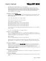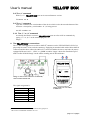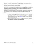
1
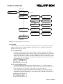
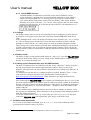
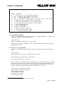
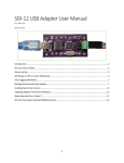
User’s manual YELLOW BOX I2C testadaptor for Texas Instruments TMP275 and Sensirion SHT21 sensors. Get this manual and more at: zww.ch/i2c zww.ch Tobias Zürcher Alte Feldeggstrasse 12 8008 Zürich YELLOW BOX User’s manual Table of contents 1. Introduction................................................................................................................................................ 3 2. What can YELLOW BOX do?.................................................................................................................. 3 3. Switching the device on and off ........................................................................................................... 3 4. The menu structure.................................................................................................................................. 3 4.1. I2C tests .................................................................................................................................................. 4 4.1.1. Find sensors..................................................................................................................................... 4 4.1.2. Check CINC sensors ...................................................................................................................... 4 4.1.3. Check SRDR sensors..................................................................................................................... 5 4.2. Settings .................................................................................................................................................. 5 4.3. Battery check ........................................................................................................................................ 5 4.4. Setting up the communication over the USB interface.............................................................. 5 5. Available serial commands.................................................................................................................... 5 5.1. The „find” command........................................................................................................................... 6 5.2. The „c” / „cn” command .................................................................................................................... 6 5.3. The „u” / „n” command ...................................................................................................................... 7 5.4. The „s” / „sn” command .................................................................................................................... 7 5.5. The „l” command ................................................................................................................................. 7 5.6. The „b” / „o” command ...................................................................................................................... 7 5.7. The „q” command................................................................................................................................ 7 5.8. The „v” command................................................................................................................................ 8 5.9. The „r” command................................................................................................................................. 8 5.10. The „?” or „h” command ................................................................................................................... 8 6. The YELLOW BOX’s connections......................................................................................................... 8 Document versions creation date author remarks / changes 2011-08-06 Tobias Zürcher initial version User’s manual YELLOW BOX 1. Introduction In the Tecan „SOL“- device, all temperatures and humidities are being measured by sensors with an I2C bus1. Since all these sensors come calibrated out of the box and since they can be read digitally, there is no need (and also no possibility) to calibrate them or the attached electronic. The read measurement value is unaffected by the cable length or the wiring. On the other hand, the sensors can’t be checked with a standard multi meter. This is, where you need YELLOW BOX. 2. What can YELLOW BOX do? ~ YELLOW BOX can find up to eight Texas Instruments TMP 275 sensors (because of eight different possible addresses) and one Sensirion SHT21 sensor (because its address can’t be changed). ~ YELLOW BOX can show all the temperatures and the humidity of the sensors built in a „SOL“- „CINC” or „SRDR” module. ~ YELLOW BOX can be connected to a computer’s USB port and controlled via a terminal program to log the measured data every 1…120 seconds. 3. Switching the device on and off Put two AA- sized batteries in the enclosure on the back side. Any type including rechargeable batteries will work and also weak batteries down to a common voltage of 1.3V (e.g. 0.65V per cell), due to the use of an internal voltage booster. The device just switches off at too low voltages. To switch on the device, push the joystick to the right and then, as it says on the display, up and down. This is to prevent the device from being switched on accidentally. Now we see the main screen, where the device can also be switched off again by a left- push: Connecting a powered USB cable to the device switches it on immediately and it also can’t be switched off in this mode. With inserted batteries it stays switched on after removing the USB cable, but can be switched off again with a left- push in the main screen. 4. The menu structure YELLOW BOX’s (tiny) menu structure is shown in Image 1. The arrows show how to navigate between the different functions. Section 4 describes all the functions in this menu. 1 2 I C bus is a registered trademark by NXP, formerly Philips Semiconductors. page 3 of 8 pages YELLOW BOX User’s manual to batt. check switch off I2C testadaptor V1.0 zww.ch (main screen) I2C tests find sensors SHT: 1TMP@ SHT:1 TMP@70+ 70+ 1, 3, 7, 8 check CINC sensors RT 22.5, HT 37.0 T_C 13.0,H 32.5 check SRDR RT 23.0, RH 55.6 T_C 13.5,H 32.5 sensors settings set contrast current contrast 3 set backlight mode backlight mode always on (USB) battery check 2.8V (min:1.3V) to main screen Image 1: The YELLOW BOX’s menu structure 4.1. I2C tests There are three tests to either find all sensors attached to a bus or to show the measurement values of the sensors. The voltage applied to the sensors is 3.3V and the I2C bus speed is 20kbps, as in the „SOL“- device. 4.1.1. Find sensors This function scans the bus for connected sensors. „SHT: 1” means that one SHT 21 sensor has been found on the bus, whereas „SHT: 0” means that there is no such sensor connected to the bus. Since this sensor has a fixed address on the I2C bus, there is no need to show the sensor’s address. Connected TMP275 sensors are displayed with their address. The screen below shows such sensors at the addresses 70+1, 70+3, 70+7 and 70+8, which is: 71, 73, 77 and 78. 4.1.2. Check CINC sensors All four measurement values of the four TMP275 sensors in a „CINC” module are presented on the display and updated twice per second. Currently, the temperatures are being rounded to 0.5°C. Missing sensors shown up as a question mark. „RT” means: Room Temperature (in the cooled air channel), „HT” means: Heated Temperature (of the aluminium plate), „T_C” means: TEC Cold (the cold side of the Peltier element) and the following „H” means the hot side of the TEC, all values in °C: page 4 of 8 pages YELLOW BOX User’s manual 4.1.3. Check SRDR sensors An SRDR module accommodates one SHT21 sensor and two TMP275 sensors. Again, the display is updated twice per second and the temperatures of the TMP275 sensors are being rounded to 0.5°C, missing sensors shown up as a question mark. „RT” means: Room Temperature (in the cooled air channel), „RH” means: Relative Humidity in % (of the cooled air), „T_C” means: TEC Cold (the cold side of the Peltier element) and the following „H” means the hot side of the TEC, all temperatures in °C: 4.2. Settings The display contrast can be set in the corresponding screen by pushing the joystick stepwise up and down. Leaving this screen stores the value in the internal EEPROM to keep the set value. In the „backlight mode” screen, the display’s backlight can be switched „off”, „on” or „always on”. The last setting means, that the device stores the mode and starts up always with the backlight on, while with the „on” setting, the device starts up without backlight, next time. These settings can be made in battery powered mode, although the backlight is only powered in USB- powered mode. This is, because the required current of 60mA is quite a lot for the batteries and the voltage of weak batteries could drop that much, that the device immediately switches off. 4.3. Battery check The battery voltage is being measured and displayed. „(min 1.3V)” says, that YELLOW BOX can operate down to this voltage. At lower voltage levels, NiMH batteries could be damaged because of a too deep discharge level. 4.4. Setting up the communication over the USB interface The built- in USB interface is an FTDI FT232R chip. Today’s Windows2 versions recognize this chip and automatically install the appropriate device driver. However, drivers for Windows, Mac and Linux can also be found on the internet. Go to ftdichip.com drivers VCP drivers. To communicate with the device, a terminal program is required. Windows Vista2 / 72 don’t come with such a program anymore, but a good alternative can be found here: https://sites.google.com/site/terminalbpp/. Other alternatives are: Hyperterminal Private Edition, TeraTerm, Putty and Realterm. After connecting the YELLOW BOX to the computer (and installing the drivers), a new COM port with a higher number as the system’s built-in COM ports will be available in the terminal program. The new COM port can also be found in „Control panel” „Hardware and Sound” „Devices and Printers” as „FT232R USB UART”. „Properties” shows the number of the added COM port. For the communication, standard parameters have been chosen: 9600bps, 8 data bits, 1 stop bit, no parity, no handshaking. These values have to be set properly in the terminal program to make the communication run. To test the communication, send a „q”, followed by the „enter” key („q ”) over the serial connection. YELLOW BOX will respond with „quit” and go to the main screen. 5. Available serial commands To see a list of all available commands, type „h ” or „? ”. A list of all commands will be presented in the terminal window, see Image 3. 2 Windows and its OS names are registered trademarks of Microsoft Corporation, US. page 5 of 8 pages User’s manual YELLOW BOX I2C Testadaptor help ‐‐‐‐‐‐‐‐‐‐‐‐‐‐‐‐‐‐‐‐‐‐ RS232‐ commands: f ‐‐> find and list all connected sensors c / c0 ‐‐> measure CINC temperatures once s / s0 ‐‐> measure SRDR temp. / rh once sn / cn ‐‐> log CINC or SRDR temp. / rh every n sec. (n=1..120) n ‐‐> numbers only in output table (default) u ‐‐> units and identifiers too in output table l ‐‐> local mode (unlock joystick in log mode) b ‐‐> switch backlight on o ‐‐> switch backlight off q ‐‐> quit to main menu v ‐‐> report firmware version r ‐‐> report device serial number ? / h ‐‐> show this help screen Image 2: List of available commands 5.1. The „find” command Typing „f ” changes to the „find sensors screen” as described in chapter 4.1.1 and puts out a text like the following in the terminal program: find sensors: SHT21:1, TMP275 @ address: 71,73,77,78 Also here, it only shows if an SHT21 sensor is connected and puts out the addresses of the found TMP275 sensors. 5.2. The „c” / „cn” command Typing „c ” changes to the CINC sensor values screen and puts out the measured values once: CINC sensors RT:22.5°C,HT:37.0°C,TEC_C:13.0°C,TEC_H:32.5°C A missing sensor is reported with a question mark: RT:?,HT:37.0°C,TEC_C:?,TEC_H:? The „n” in the „cn” command stands for a number between 0 and 120. With 0, the command does exactly the same as above, but with other values, it puts out the measured data every n seconds. To provide easy copy- paste to a spreadsheet program like Excel3, units are only shown in the header of such an output table. For example „c2 ” puts out: CINC sensors, sampling rate:2s RT/°C,HT/°C,TEC_C/°C,TEC_H/°C 23.0,34.0,17.5,28.0 23.0,34.0,17.5,28.0 23.0,34.5,17.5,28.5 23.5,34.0,17.5,28.5 3 Excel is a registered trademark of Microsoft corporation US. page 6 of 8 pages YELLOW BOX User’s manual The output can be stopped with the „q ” (quit) command. Because most users want to use the data in a spreadsheet program afterwards, this is the default output format. Anyhow, as soon as the header is being pushed out at the top of the terminal program because the table length exceeds the program’s window height, this table is rather meaningless if the user only wants to monitor the output in the terminal program. That’s, why there is a „u” command. 5.3. The „u” / „n” command Typing „u ” forces YELLOW BOX to put out units and identifiers in the output table. This influences the „cn” (CINC output table) and the „sn” (SRDR output table, see below). The device responds with: units and identifiers in output table Whereas the table shown above now looks like this: CINC sensors, sampling rate:1s RT:23.0°C,HT:34.0°C,TEC_C:17.5°C,TEC_H:28.0°C RT:23.0°C,HT:34.0°C,TEC_C:17.5°C,TEC_H:28.0°C RT:23.0°C,HT:34.5°C,TEC_C:17.5°C,TEC_H:28.5°C RT:23.5°C,HT:34.0°C,TEC_C:17.5°C,TEC_H:28.5°C To switch back to the output table format without identifiers and values, enter „n ” and the device responds: no units and identifiers in output table 5.4. The „s” / „sn” command The „s” command is the equivalent to the „c” command, but for SRDR sensors. Typing „s ” changes to the SRDR sensor values screen and puts out the measured values once, here shown with units and identifiers in the output table („u” command): SRDR sensors RT:25.5°C,RH:58.9%,TEC_C:15.5°C?,TEC_H:30.5°C Missing sensors are also reported with a question mark and a table can be put out the same way as with the „cn” command, the „u” and „n” command work again as described in section 5.3. 5.5. The „l” command With the „sn” and „cn” command, YELLOW BOX switches to remote mode which means that the joystick is being locked to prevent from accidentally interrupting the data output. „l ” unlocks the joystick (switches back to local mode) but an ongoing output („cn” / „sn” commands) continues. The device also switches back to local mode when it gets disconnected from the computer’s USB port. 5.6. The „b” / „o” command The display’s backlight can be switched on („b”) and off („o”) remotely – as an indicator or to support the advent season… 5.7. The „q” command Typing „q ” in the terminal program stops an ongoing output and sets the device to its main screen. page 7 of 8 pages User’s manual YELLOW BOX 5.8. The „v” command With a „v ”, YELLOW BOX puts out its current firmware version: firmware V1.0 5.9. The „r” command Upon this command, the serial number of the device which is also shown at the bottom of the enclosure’s inscription („serial number: 11”) is being put out: serial number:11 5.10. The „?” or „h” command As already described in section 5, YELLOW BOX puts out a list of all its commands by typing „? ” or „h ” in the terminal program, see Image 2. 6. The YELLOW BOX’s connections The I2C bus is brought out on two Micro-MaTch4 connectors on the YELLOW BOX’s PCB. It is physically the same I2C bus on both connectors. Equipping an attached cable with a Micro-MaTch connector and the other cable with a Micro-Fit5 connector enables the user to test both, the sensorequipped PCBs and „SOL“- „CINC” or „SRDR” modules. Image 3 shows the location of pin 1 and 6 on the PCB and Image 4 at the cables coming out of the enclosure. 1 6 1 6 YELLOW BOX up back (off) enter (on) zww.ch down Image 3: The two I2C connectors on the PCB, seen from the bottom side I2C Testadaptor Tests Texas Instruments TMP275 and Sensirion SHT21 sensors. For a manual, visit zww.ch/i2c. serial number: 07 The signal assignment is: pin / wire number 1 2 3 4 5 6 4 5 signal 3.3V SCL SDA GND GND GND Image 4: The two I2C cables at the device Micro-MaTch is a trademark of Tyco Electronics group US. Micro-Fit is a trademark of Molex Inc. US. page 8 of 8 pages