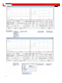
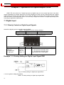
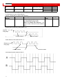
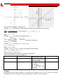
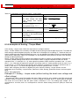
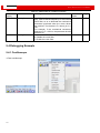
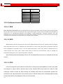
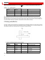
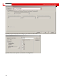
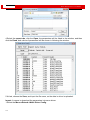
1
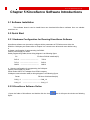
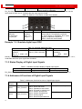
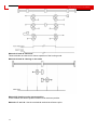
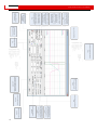
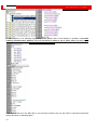
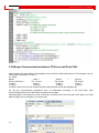
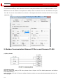
Kinco
Servo User Manual
Kinco JD
JD Series
伺服系列使用手册
Note: “Start finding the origin” signal is a pulse signal, requires only a rise, not need to always be on. If you
want to start next time, a rise pulse is enough.
(4). After the external find the origin, computer monitoring picture is as follows:
106