1
Kinco
Servo User Manual
Kinco JD
JD Series
伺服系列使用手册
Appendix 7: Common Objects List
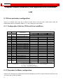
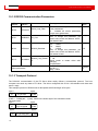
Based on the data communication protocols described in Chapter 10,all parameter values are transferred in
hexadecimal data. In the later sections of this document, we adopt the hexadecimal system and use Index
(16-bit index) and Subindex (8-bit subindex) to represent the register addressing. The digit 08 indicates the
register will store data up to 1 byte, and the digit 10 indicates that the register will store data up to 2 bytes,
and the digit 20 indicates the register will store data up to 4 bytes. It also covers the storage digits and
read/write property of the register, read or write flag (RW), read-only or write-only flag (RO, WO), and
mapping flag (M).
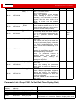
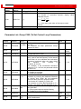
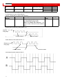
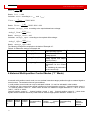
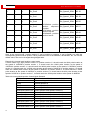
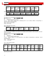
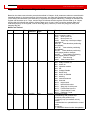
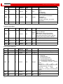
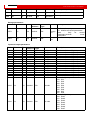
Modes and Control:
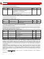
Index
Subindex
Bits
6040
00
6041
6060
163
Command
Type
RW
Unit
Descriptions
10
Modbus
Address
0x3100
bitcode
00
10
0x3200
RO
bitcode
00
08
0x3500
WO
number
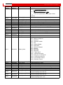
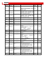
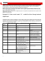
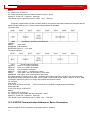
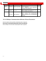
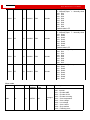
Use control word to change status of
drive =>machine state
0x06
Motor power off
0x0F
Motor power on
0x0B
Quick stop, load tops-voltage
switched off
0x2F-3F
Start absolute positioning
immediately
0x4F-5F
Start relative positioning
immediately
0x103F
Start absolute positioning
while target position changes.
0x105F
Start relative positioning
while target position changes
0x0F-1F
Start homing
0X80
Clear internal error.
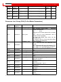
Status byte shows the status of drive
bit0:ready to switch on
bit1:switch on
bit2:operation enable
bit3:falt
bit4:Voltage Disable
bit5:Quick Stop
bit6:switch on disable
bit7:warning
bit8:internal reserved
bit9:reserved
bit10: target reach
bit11: internal limit active
bit12: Step.Ach./V=0/Hom.att.
bit13: Foll.Err/Res.Hom.Err.
bit14: Commutation Found
bit15: Referene Found
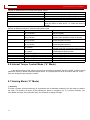
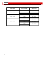
Operation modes:
1 Positioning with position loop
3 Velocity with position loop
-3 Velocity loop (immediate velocity
mode)
-4 Master/slave or pulse/direction control
mode
6 Homing
7. CANOPEN based motion interpolation