1
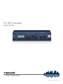
371 SPL Computer
User’s Guide
Safety
6408 216th Street SW | Mountlake Terrace, WA 98043 USA
T +1.425.778.7728 F +1.425.778.7727 | www.SymetrixAudio.com
User’s Guide
2
Safety
371 SPL Computer
What Ships in the Box
• A 371 hardware unit.
• One PS-3 (115 VAC), or PS-3E (230
VAC) power supply.
• This User’s Guide.
Getting Help
Voice Processor 2x, the Windows
application that controls the hardware,
includes a help module which acts as a
complete User’s Guide for both hardware
and software.
If you have questions beyond the scope
of this Quick Start Guide or the help
module, contact our Customer Support
Group in the following ways:
Important Safety
Instructions
!
@
#
$
%
^
&
8:00 am to 4:30 pm
Monday through Friday,
Pacific Time
Read these instructions.
Keep these instructions.
Heed all warnings.
Do not use this apparatus near water.
This apparatus shall not be exposed to
dripping or splashing and no objects
filled with liquids, such as vases, shall be
placed on the apparatus.
No user serviceable parts inside. Refer servicing to qualified service personnel.
Il ne se trouve a l’interieur aucune piece pourvant entre reparée l’usager.
S’adresser a un reparateur compétent.
G
The lightning flash with arrowhead
symbol within an equilateral triangle is
intended to alert the user of the presence
of uninsulated “dangerous voltage”
within the product’s enclosure that may
be of sufficient magnitude to constitute
a risk of electric shock to persons. The
exclamation point within an equilateral
triangle is intended to alert the user of
the presence of important operating and
maintenance (servicing) instructions in the
literature accompanying the product (i.e.
this Quick Start Guide).
G
CAUTION: To prevent electric shock,
do not use the polarized plug supplied
with the unit with any extension cord,
receptacle, or other outlet unless the
prongs can be fully inserted.
G
Power Source: This Symetrix hardware
uses a switching power supply that
automatically adjusts to the applied
voltage. Ensure that your AC mains
voltage is somewhere between 100-240
VAC, 50-60 Hz. Use only the power
cord and connector specified for the
product and your operating locale. A
protective ground connection, by way of
the grounding conductor in the power
cord, is essential for safe operation. The
appliance inlet and coupler shall remain
readily operable once the apparatus has
been installed.
G
User Serviceable Parts: There are no
user serviceable parts inside this Symetrix
product. In case of failure, customers
inside the U.S. should refer all servicing to
the Symetrix factory. Customers outside
the U.S. should refer all servicing to an
authorized Symetrix distributor. Distributor
contact information is available online at:
http://www.SymetrixAudio.com.
Do not block any ventilation openings.
Install only in accordance with the
manufacturer’s instructions.
(
This apparatus shall be connected to
a mains socket outlet with a protective
earthing connection. Do not defeat
the safety purpose of the polarized or
grounding-type plug. A polarized plug has
two blades with one wider than the other.
A grounding type plug has two blades
and a third grounding prong. The wide
blade or the third prong are provided for
your safety. If the provided plug does not
fit into your outlet, consult an electrician
for replacement of the obsolete outlet.
This device complies with part 15 of
the FCC Rules. Operation is subject
to the following two conditions: (1)
This device may not cause harmful
interference, and (2) this device must
accept any interference received,
including interference that may cause
undesired operation.
DE CHOC ELECTRIQUE
AVIS: RISQUE
NE PAS OUVRIR
SEE OWNERS MANUAL. VOIR CAHIER D’INSTRUCTIONS.
Clean only with dry cloth.
Do not install near any heat sources such
as radiators, heat registers, stoves, or
other apparatus (including amplifiers) that
produce heat.
Web:http://www.SymetrixAudio.com
TO REDUCE THE RISK OF FIRE OR
SHOCK DO NOT EXPOSE
WARNING: ELECTRIC
THIS EQUIPMENT TO RAIN OR MOISTURE
Follow all instructions.
*
Tel: +1 (425) 778-7728
CAUTION
RISK OF ELECTRIC SHOCK
DO NOT OPEN
This Class B Digital apparatus meets
all requirements of the Canadian
Interference-Causing Equipment
Regulations
BL
Protect the power cord from being
walked on or pinched particularly at
plugs, convenience receptacles, and the
point where they exit from the apparatus.
Cet appariel numerique de la classe
B respecte toutes les Exigences du
Reglement sur le materiel brouilleur
du Canada.
BM
Only use attachments/accessories
specified by the manufacturer.
BN
Use only with the cart, stand,
tripod, bracket, or table
specified by the manufacturer,
or sold with the apparatus.
When a cart is used, use
caution when moving the cart/apparatus
combination to avoid injury from tip-over.
BO
Unplug this apparatus during lightning
storms or when unused for long periods
of time.
BP
Refer all servicing to qualified service
personnel. Servicing is required when
the apparatus has been damaged in any
way, such as power-supply cord or plug
cord is damaged, liquid has been spilled
or objects have fallen into the apparatus,
the apparatus has been exposed to rain
or moisture, does not operate normally, or
has been dropped.
3
Overview
User’s Guide
Introduction
This simple, yet sophisticated SPL Computer is
designed to ensure that foreground music and/or paging
announcements are always clearly audible and distinct,
but never too loud. Proprietary AmbiSense™ technology
monitors ambient noise levels continuously, not just during
gaps in the audio program, and responds quickly to sudden
changes. Setup is simple: enter the parameters of the
“normal” acoustic environment, then tell the 371 how much
to change the
gain, and how quickly to raise or lower it, whenever
measured noise levels deviate from the parameters you
have set. The front panel LCD guides you with step-through
menus. Install a simple, precise and cost-effective solution:
the 371 SPL Computer, backed by over 15 years of SPL
processing innovation from Symetrix, the engineering-driven
company of signal processing specialists.
Feature Summary
External Microphone connection for Continuously Monitoring
Ambient Noise Levels
Using an external microphone to measure changes in the ambient noise level, AmbiSense™ technology responds to environmental noise changes in realtime — not just during gaps in audio program.
Headphone Monitoring
Monitor the sense signal using a separate front panel headphone output.
3 Operating Modes
Active: Indicates continuous measurement of the ambient noise level.
History: Displays the lowest and highest SPL readings from when the unit was last reset
Bypass: Bypasses the unit. Audio passes through at unity gain.
Signal Path
Accepts mono or stereo signals via Euroblock connectors.
Easy Calibration
Uses step-through menus on the front panel LCD. Calibration performed under typical installation conditions. No waiting for the
quietest or noisiest ambient conditions.
Ratio Adjustment
Choose an adjustment ratio of SPL change vs. program level change.
Sense Signal Measuring
Display numeric reading and relative bargraph of the signal appearing at the sense terminals.
Gain Controls
Set minimum and maximum limits for SPL gain range. Gain range is –30 dB to +20 dB.
Averaging Time
Choose integration time of the running average SPL.
Phantom Power
Sense input provides 15 VDC phantom power to microphone. Enable or disable in front panel LCD menu.
Ducker Control
Ducker input provides momentary reduction of program level (from 0 dB to –40 dB) and inhibits sense operation for the duration
of the externally supplied line level ducking control signal.
Remote Control Option
Connect rotary potentiometer or Symetrix RC-3 for remote control of output level.
6408 216th Street SW | Mountlake Terrace, WA 98043 USA
T +1.425.778.7728 F +1.425.778.7727 | www.SymetrixAudio.com
4
Front/Rear Panel
371 SPL Computer
Front Panel
Item
Description
LCD Display
Two lines show levels and settings of selected menu option.
Next
From normal operation, the first press enters the setup mode; subsequent presses step through the setup process and save settings.
Exit
Exits the setup mode and saves changes to settings. The unit reverts to normal operation.
Adjust
Turn to change the selected parameter.
Cal
Press to have the 371 read the current ambient level and equate this reading to 0 dB (unity) gain. Displays the relative ambient reading
which it considers as normal. CAL is only active in normal operating mode and when setup is unlocked.
Headphone
1/4 inch TRS jack suitable for headphone impedances of 60 Ohms or higher, stereo or mono. Enables listening to the output of the
sensing system. Helpful for troubleshooting or for figuring out what the 371 sense mic is actually ‘hearing’.
Monitor
Adjusts the volume level at the headphone jack.
Rear Panel
Item
Description
7-pin DIN Connector
Connect the 7-pin DIN plug end of a Symetrix PS-3 (115 VAC) or PS-3E (230 VAC) here. Connect the AC power connector end of the
PS-3 or PS-3E to an AC power source that is of the correct voltage and frequency as marked on the PS-3 or PS-3E.
Remote Gain
Supplies 10 VDC, a ground, and a signal input for a remote gain trim control. Use standard 10k Ohm linear potentiometer or Symetrix
model RC-3.
Ducker Control
Balanced input for the 371. 20k Ohm balanced bridging. If connecting unbalanced sources, refer to the Input and Output Connector
Wiring section. Triggers the internal ducker circuit to duck program audio and / or “freeze” the SPL computing functions.
Line Output
These connectors deliver a differential balanced output at 200 Ohm source impedance. If connecting unbalanced loads, refer to the
Input and Output Connector Wiring section.
Line Input
Balanced input for the 371. 20k Ohm balanced bridging. If connecting unbalanced sources, refer to the Input and Output Connector
Wiring section.
Sense Input
Accepts most standard dynamic and condenser microphones. Built-in mic preamp can supply 15 VDC phantom power and gain
ranging from 0 dB to 70 dB in 10 dB steps.
NOTE: Detachable Euroblock connectors are designed for use with bare wire. Do not tin
stranded wires before inserting them into the connectors.
5
Basic Setup
PS3 Power
Supply
CD Player
REMOTE
GAIN
www.SymetrixAudio.com
ENGINEERED AND ASSEMBLED OF U.S. AND IMPORTED MATERIALS
BY SYMETRIX, INC. MOUNTLAKE TERRACE, WA USA
THIS UNIT CONTAINS NO USER SERVICEABLE PARTS
CONNECT TO
SYMETRIX
PS-3 OR PS-3E
POWER SUPPLY
ONLY
DUCKER
CONTROL
LINE OUTPUT
RIGHT
LEFT
CONÇU ET ASSEMBLÉ DES MATÉRIAUX DES ÉTATS UNIS ET
IMPORTÉS PAR SYMETRIX, INC. MOUNTLAKE TERRACE, WA USA.
PAS DES ELEMENTS SERVIABLE PAR UTILISATEUR
2
Connect Output
to Amplifiers,
EQs, Speakers, etc.
Amplifier
Speakers
Hardware Set-up Checklist
Required
Optional
Task to do
6
Connect page/program input source
6
Connect 371 to output device
6
Connect sense microphone
6
Connect input source for ducking
6
Connect remote volume control pot
6
Connect switch for external
ducking control
Connect to AC power supply
6
6
LINE INPUT
RIGHT
LEFT
Sensing Mic
SENSE
INPUT
Sensing Mic 2
(optional)
371
+10V
POWER
INPUT
Connect your input devices.
SPL
COMPUTER
1
Connect PS-3 Power
Supply to AC Power.
Engineered by Symetrix
in the U.S.A.
3
User’s Guide
Connect headphones to hear what the 371 is
sensing
6408 216th Street SW | Mountlake Terrace, WA 98043 USA
T +1.425.778.7728 F +1.425.778.7727 | www.SymetrixAudio.com
6
371 SPL Computer
Sensing Microphone Considerations
Type of Microphone
Location of Microphone
For most applications, an inexpensive low-impedance,
omnidirectional microphone, such as a lavalier microphone
works adequately.
The sensing microphone needs to “hear” the ambient sound
within the controlled space. It is vital that you place the
microphone where it primarily picks up a majority of noise
rather than the paging or music that is going through the
system.
Some installers have used boundary microphones with good
success (they’re unobtrusive).
Do not locate the sensing microphone near a localized noise
source that is not typical of the ambient noise level of the
controlled zone, for example, the noise from a large machine
of some sort, or maybe a kids play area, or a video game. If
you do this the 371 will think that the zone is noisier than it
really is.
Other installers have mounted microphone cartridges
(available from Mouser Electronics in the U.S.) inside
electrical boxes equipped with a single-holed cover.
In smaller rooms or acoustically live spaces, a directional
microphone is a good choice, because you can use its
position to favor the ambient sound and minimize pickup
from the sound system loudspeakers.
The best sense mic placement ensures that the majority of
the signal picked up by the sensing microphone is ambient
noise. AmbiSense allows music or page pickup without ill
effects on its operation—up to about a 50:50 mix of music/
page to ambient. In an extreme case where the sense
microphone picks up 100% music/ page (0% ambient
noise), AmbiSense will not be able to extract enough
information to use for gain control.
If the sense mic is positioned a relatively long distance from
the ambient noise source(s), a directional microphone may
improve system performance.
NOTE: No matter what kind of microphone you
choose, during calibration the 371 will adapt itself to the
characteristics of that mic.
Disclaimer: In recognition of the relative risks and
benefits to both the Integrator and SYMETRIX, INC,
any recommendation or suggestion relating to the use
of the Products made by SYMETRIX, INC or any other
manufacturer either in technical literature or in response
to a specific inquiry or otherwise, is given in good faith.
HOWEVER, it is for the Integrator to satisfy himself that
the products are fit for the purpose of being utilized by a
Consumer as the end-user of the Products. To the fullest
extent permitted by law, SYMETRIX, INC is not liable for any
and all claims, losses, costs, or unforeseen damages of any
nature whatsoever. It is intended that this limitation apply
to any and all liability or cause of action however alleged or
arising, unless otherwise prohibited by law.
Capability of Sound System to Match the
Maximum Required Level
Calibrate at a quiet-to-average time in the controlled space.
It helps if you have an estimate (sound pressure level) of the
maximum desired level. Check the sound system to see that
it is capable of delivering that level.
7
Connecting a Volume Controller
Connect a potentiometer or another device
which generates voltage between the 10 VDC
output and ground of the 371. The value of the
potentiometer isn’t critical; anything between
10k and 100k (linear taper) will do. For best
accuracy, use the supplied 10 VDC reference
at Pin 1 of the connector to drive the high side
of the potentiometer.
www.SymetrixAudio.com
ENGINEERED AND ASSEMBLED OF U.S. AND IMPORTED MATERIALS
BY SYMETRIX, INC. MOUNTLAKE TERRACE, WA USA
THIS UNIT CONTAINS NO USER SERVICEABLE PARTS
POWER
INPUT
REMOTE
GAIN
CONNECT TO
SYMETRIX
PS-3 OR PS-3E
POWER SUPPLY
ONLY
DUCKER
CONTROL
+10V
The 371 allows you to have remote gain
control. You can connect a potentiometer or
the Symetrix RC-3 Remote Control to the
REMOTE GAIN Euroblock connectors.
User’s Guide
CONÇU ET ASSEMBLÉ DES MATÉRIAUX DES ÉTATS UNIS ET
IMPORTÉS PAR SYMETRIX, INC. MOUNTLAKE TERRACE, WA USA.
PAS DES ELEMENTS SERVIABLE PAR UTILISATEUR
Potentiometer
CCW
Enable Remote Control From the
LCD menu
CW
For the remote volume control to work, you
must enable remote control.
To enable remote control:
! From the LCD menu display, select the
menu option Output Trim.
@ Turn ADJUST fully counterclockwise (below
the setting for –10) to choose Remote. The
actual gain according to the remote pot
setting now displays.
# Press EXIT or NEXT to save setting.
www.SymetrixAudio.com
ENGINEERED AND ASSEMBLED OF U.S. AND IMPORTED MATERIALS
BY SYMETRIX, INC. MOUNTLAKE TERRACE, WA USA
THIS UNIT CONTAINS NO USER SERVICEABLE PARTS
POWER
INPUT
REMOTE
GAIN
CONNECT TO
SYMETRIX
PS-3 OR PS-3E
POWER SUPPLY
ONLY
+10V
Keep gain in –10 dB to +10 dB range for
accurate operation. However, a remote pot can
“dim” the audio down to –50 dB temporarily.
CONÇU ET ASSEMBLÉ DES MATÉRIAUX DES ÉTATS UNIS ET
IMPORTÉS PAR SYMETRIX, INC. MOUNTLAKE TERRACE, WA USA.
PAS DES ELEMENTS SERVIABLE PAR UTILISATEUR
CCW
Symetrix RC-3
6408 216th Street SW | Mountlake Terrace, WA 98043 USA
T +1.425.778.7728 F +1.425.778.7727 | www.SymetrixAudio.com
8
CW
DUCKER
CONTROL
External Ducking Control
371 SPL Computer
The DUCKER CONTROL input is normally
connected to a line level audio signal from
any source you would like to use to trigger a
momentary decrease in volume (ducking).
Alternatively, you can choose to attach to the
DUCKER CONTROL a momentary switch or
relay contact to manually control ducking.
Such a switch might be a push-to-talk switch
contact within a microphone or a manual
switch on a control panel. One isolated SPST
(single pole single throw) normally open
contact is required.
www.SymetrixAudio.com
ENGINEERED AND ASSEMBLED OF U.S. AND IMPORTED MATERIALS
BY SYMETRIX, INC. MOUNTLAKE TERRACE, WA USA
THIS UNIT CONTAINS NO USER SERVICEABLE PARTS
POWER
INPUT
CONNECT TO
SYMETRIX
PS-3 OR PS-3E
POWER SUPPLY
ONLY
REMOTE
GAIN
DUCKER
CONTROL
+10V
NOTE: The signal applied to the DUCKER
CONTROL input does not get mixed with the
program audio. In other words, the ducking
input signal functions only as a control signal.
Paging System
CONÇU ET ASSEMBLÉ DES MATÉRIAUX DES ÉTATS UNIS ET
IMPORTÉS PAR SYMETRIX, INC. MOUNTLAKE TERRACE, WA USA.
PAS DES ELEMENTS SERVIABLE PAR UTILISATEUR
To enable ducking, you must also set
parameters in the LCD menu.
Set Ducking Parameters in LCD
Setup Menu
External switch or relay contact
! If you are using audio to control ducking
set the Ducker Threshold between -30
dBu and +20 dBu. The correct setting is
dependent up the average level of your
incoming signal. Experiment until it sounds
right to you.
@ If you are using a switch to control ducking
then set the Ducker Threshold somewhere
between 0 and +10 dBu.
# Set the Ducker Depth for the desired
amount of signal attenuation when
ducking is active.
Ducking takes place whenever the audio
ducking signal exceeds the threshold or
whenever the switch contacts are closed,
depending upon which ducking method you
have chosen.
Sensing is inhibited while ducking is in
process, therefore gain remains fixed during
the ducking event.
NOTE: If Ducker Depth is set to zero
applying a ducking signal will freeze the gain.
9
Input/Output Wiring
User’s Guide
Input Connections
Terminal Strip [balanced]
These connectors are designed for use with bare wire.
Do not tin stranded wires before inserting them into
the connectors.
Balanced
Terminal Strip
For Unbalanced Connections
Euroblock
Connector
Channel Input/Output
NOTE: Detachable Euroblock
connectors are designed for use
with bare wire. Do not tin stranded
wires before inserting them into
the connectors.
Connect the (–) input terminal to the source ground at
the source.
Feeding unbalanced inputs directly from balanced
outputs is not recommended due to the possibility
of ground loops. You may want to use an isolation
transformer to break the ground connection and
eliminate the ground loop.
XLR Female Plug [balanced]
Pin 2
Pin 3
Pin 1
Pin 2 = (+) Plus
Pin 3 = (–) Minus
Pin 1 = Ground
Euroblock
Connector
Channel Input
Output Connections
These connectors deliver a differential balanced output
signal (mimics a grounded center tap transformer winding).
For Unbalanced Loads
XLR Male Plug [balanced]
With unbalanced loads, it is preferable to carry the
low side of the input all the way back to the ground
connection of the source.
Pin 2 Pin 2 = (+) Plus
Pin 3 Pin 3 = (–) Minus
Pin 1 Pin 1 = Ground
Use the (+) output terminal and the ground terminal.
Ignore (float) the (–) output terminal.
Euroblock
Connector
Channel Output
TRS 1/4" Plug [balanced]
Tip = (+) Plus
Ring = (–) Minus
Sleeve = Ground
Euroblock
Connector
Channel Input/Output
TS 1/4" Plug [unbalanced]
Tip = (+) Plus
Sleeve = Ground
! IMPORTANT NOTICE 1
!
1
Euroblock
Connector
Channel Input
The wiring diagrams on this page are included for
information purposes only.
Symetrix can not anticipate exactly what connection
is needed at the non-371 end of the cable. It is
the user’s responsibilty to determine what
connection is needed.
TS 1/4" Plug [unbalanced]
Tip = (+) Plus
Sleeve = Ground
In addition, Symetrix accepts no responsibilty for
injury or damage caused by user created wiring.
6408 216th Street SW | Mountlake Terrace, WA 98043 USA
T +1.425.778.7728 F +1.425.778.7727 | www.SymetrixAudio.com
10
Euroblock
Connector
Channel Output
System Setup
371 SPL Computer
System Set-up Checklist
Required
Recommended
Optional
Task to do
Choose Operating Mode
6
6
View calibration Status
6
Collect History of highest and lowest SPLs
View Sense levels
6
6
Enable Phantom Power
6
Set Sense Input Gain
Specify Output Trim
6
Set MIN Limit
6
Specify Averaging Time
6
Specify Gain: Sense Ratio
6
6
Set Ducker Depth
6
Set Ducker Threshold
Lock or Unlock Setup
6
General Operation of the 371’s
LCD Menu Screen
Use the two push buttons, NEXT and EXIT, along
with the parameter adjustment knob, ADJUST, to gain
access to menu setup options in the LCD display.
!Press NEXT to enter the setup mode.
@ Turn ADJUST to select a specific value or choice.
# Press NEXT again to gain access to another menu
option. Subsequent presses of NEXT change menu
options and save settings.
$ Press NEXT or EXIT to end the setup process, save
any changes made, and return the unit to normal
operation.
—or—
Allow 20 minutes of inactivity, after which the unit
automatically returns to normal operation.
After setup is complete, calibrate the unit
(See the Calibration section).
11
System Setup
User’s Guide
Press NEXT to advance through the different
Menu selections
Status
Startup Screen
Cal:
Startup Screen displays current gain applied by the unit.
When the 371 senses a signal at the DUCKER INPUT, Duck
displays.
Ambient signal level measured at the last sense period.
Min:
Operating mode
Max:
Turning the ADJUST knob lets you select one of these three
operational modes
Maximum gain that the 371 is permitted to have.
Active
Displays numeric readings of the highest and lowest SPLs
from whenever the 371 unit was calibrated or from when the
setting was last reset.
Displays the current calibration status of the 371.
Minimum gain that the 371 is permitted to have.
History: Reset to Zero
Select this mode if you want the 371 to vary the gain of this
program channel to match the ambient noise level.
Resetting the 371 to Zero starts a new history period, where
the 371 begins to collect the highest and lowest relative SPL
readings.
How Sampling Works—The 371 takes SPL measurements
every 10 ms through the sensing microphone.
History
Sense
Select this mode if you only want the 371 to collect data
about the highest and lowest ambient SPL in the installation
zone(s).
Displays bargraph of current ambient noise level.
Phantom Power
The 371 does not perform any gain control in this mode. You
can determine the start of the history period or collection
of data. See in this section History to reset or start the
collection of the relative SPL history.
ON +15 V, OFF
To turn on or off 15 V phantom power for the sense
microphone. Enable only if your microphone requires it.
Ducking can be made active in this mode if desired.
Sense Input Gain
Bypass
0, 10, 20, 30, 40, 50, 60, 70 dB
Select this mode when you want to leave the 371 physically
connected in the signal path, only pass the signal unaltered,
and never take SPL samples.
Select the amount of gain that is required for the sense
microphone.
For proper calibration, the internal preamp must produce
a signal in the range of –45 dB to 20 dB. Refer to Sense
(above) for relative SPL readings.
This feature is useful if you encounter setup problems in an
installation. You can temporarily disable the 371 until you
have the time to correct the problem. Or when the action
of the 371 is temporarily unwanted, for example, when an
unusual event is taking place.
Output Trim
–10 dB to +10 dB in 1 dB increments
You can view your control settings in this mode. Any
changes you make to your control settings in this mode, will
not take effect.
To add to or subtract from the overall output gain from the
front panel or via remote (control the output trim
with a potentiometer or with the RC-3 Remote Control).
Keep gain in –10 dB to +10 dB range for accurate
operation. However, a remote pot can “dim” the audio
down to –50 dB temporarily.
The gain is always held at unity (0 dB) in this mode.
Bypass mode is not a hard-wire bypass.
6408 216th Street SW | Mountlake Terrace, WA 98043 USA
T +1.425.778.7728 F +1.425.778.7727 | www.SymetrixAudio.com
12
System Setup
371 SPL Computer
Set MIN Limit
Ducker Depth
–30 dB up to the actual setting of the maximum limint in 1
dB increments
0 dB to –40 dB
To set the ducking range. Upon ducking, the program
outputs drop according to the value selected. External
DUCKER CONTROL signal does not mix with internal
program signal. The external control signal merely initiates
ducking action.
To adjust the lowest gain setting that the 371 uses. This
ensures a known minimum level from the sound system,
even if the ambient drops to dead silence.
Averaging Time
Ducker Threshold
1, 3, 10, 30 seconds – 1.5, 5, 15 minutes
+20 dB to –30 dB
To adjust the reaction time at which the 371 adjusts to the
ambient level. Longer running averages make the system
respond more to the trend of the ambient level rather than
the most recent events.
To set the minimum signal level needed for the 371 to
acknowledge ducking input. The 371 program outputs drop
to the Ducker Depth if the DUCKER CONTROL input rises
above the Ducker Threshold.
Gain:Sense Ratio
Setup Unlocked
0.5:1, 1:1, 1.5:1, 2:1 NOTE - The displayed ratio values are
guide lines only and not absolute values. The AmbiSense
algorithm may modify these ratios based upon the data it
gathers during the calibration process.
Unlocked, Locked
Choose to protect front panel LCD menu settings from being
altered. To lock, press and hold CAL while turning ADJUST.
Once it’s locked, pressing NEXT shows the current settings.
Any attempt to alter settings results in the display of the
message “Setup is Locked”. To unlock, press NEXT until the
display reads Setup is Locked. Press and hold CAL while
turning ADJUST. The front panel is now unlocked.
Refers to the change in gain of the 371 versus the change in
the ambient.
0.5:1 changes gain 0.5 dB for every 1 dB change in the
ambient. This makes the sound system louder in response
to increases in the ambient, but never tries to “out-shout the
crowd”.
1:1 matches gain changes to the ambient noise level.
1.5:1 changes gain 1.5 dB for every 1 dB increase in the
ambient noise level.
2:1 changes gain 2 dB for every 1 dB increase in the
ambient noise level.
NOTES:
• At a 2:1 ratio with high ambient levels, the 371 can easily
“out shout” the crowd.
• At lower ambient levels, the 371 might let the sound
system get lost in the ambient. To avoid this, choose a
higher (closer to 0 dB) minimum gain and/or a higher
ratio.
13
Calibration
User’s Guide
What Does Calibration Do?
$When the LCD menu displays Adjust to Maximum, turn
The calibration process correlates the current ambient noise
level to 0 dB (unity) gain. As the ambient SPL becomes less,
the 371 lowers its gain. Conversely, when the SPL increases,
the gain of the 371 increases.
%Next, the LCD menu displays whether calibration
ADJUST to set the maximum gain for the program output.
The gain range is 0 dB to +20 dB in 1 dB steps.
succeeded or not.
Proper calibration is vital to the proper operation of the 371.
The AmbiSense algorithm will not function correctly if the
calibration procedures are not executed.
^When calibration is finished, the 371 displays the relative
What To Do Before Calibration
Calibration can fail if the Sense Input Gain is set too low
(–45 dB) or too high (+20 dB). In the LCD setup menus,
adjust Sense Input Gain for a proper gain setting.
ambient SPL reading which it considers as normal.
What to Do If Calibration is Unsuccessful
Before calibration, setup the SENSE INPUT. System setup
menu items that control the Sense Input are Phantom Power
and Sense Input Gain.
Check Sense for the current sense input level. The setting
should be between –45 dB and +20 dB.
THIS IS IMPORTANT!
• Calibrate when the ambient noise in the area being
controlled is at a level typical of normal conditions.
You can also check the SENSE INPUT by listening with
headphones connected to AMBIENT SENSE MONITOR on
the front panel to hear what the 371 is reading.
• Use the highest paging or music input levels that you are
likely to encounter during normal operation.
What You Should Not Do After Calibration
Do not adjust the level of any volume controls in the sound
system signal path after the 371. Doing so will cause the
AmbiSense technology to yield erroneous results. Controls
that must remain fixed include amplifier input level controls,
wall-mounted L-Pad style speaker attenuators, etc.
Adjust Sense Input Gain until Sense displays a bargraph
showing a mid-level sense signal. Make sure you leave
enough headroom so that increased ambient levels do not
overdrive the sense input. For example, if you expect that
ambient noise levels will rise 20 dB above the currently
observed levels, adjust the Sense Input Gain to leave more
than 20 dB of headroom under current conditions.
Also, do not insert compressors or limiters into the signal
path after the 371. If you need to adjust amplifier input
levels, re calibrate the 371 afterward to reset the data
collected by the AmbiSense algorithm. If you need to trim
the overall system level up or down after calibration, you can
do this by adjusting the Output Trim.
Only perform calibration when the setup for the 371
is unlocked (See System Setup>Description of Menu
Options>Setup Unlocked). Pressing CAL when the setup is
locked will do nothing.
How to Calibrate
!On the front panel, press CAL. The 371 sets software
controlled gain to 0 dBu (unity). The LCD menu displays
Unity Gain … Cal to proceed.
@Adjust the other components in the sound system (music
level, power amp gain, etc.) for the desired program level
during average conditions.
#If you wish to continue with calibration then press CAL
again. If you do not wish to continue with calibration then
press EXIT and the calibration process will abort.
The 371 reads the ambient level on the SENSE INPUT.
This level will be the unity reference (0 dB) for the 371.
6408 216th Street SW | Mountlake Terrace, WA 98043 USA
T +1.425.778.7728 F +1.425.778.7727 | www.SymetrixAudio.com
14
Block Diagram
371 SPL Computer
LINE
INPUT
LEFT
LINE
INPUT
RIGHT
DUCKER
CONTROL
REMOTE
GAIN
BAL
INPUT
VCA
RMS
DETECT
BAL
INPUT
BAL
INPUT
AVERAGE
LEVEL
DETECT
ADJUST
SPL
CPU
DC AMP
MIC/LINE
INPUT
LINE
OUTPUT
RIGHT
VCA
CALIBRATE
MENU EXIT
AVERAGE
LEVEL
DETECT
MENU NEXT
RMS
DETECT
PHANTOM
POWER
SENSE
INPUT
LINE
OUTPUT
LEFT
SENSE
GAIN
BANDPASS
FILTER
15
SENSE
MONITOR
VOLUME
SENSE
HEADPHONE
Troubleshooting
User’s Guide
No output signal
Unit does not control levels as expected
Check to see that the LCD display is illuminated and the unit
is plugged in.
Using headphones connected to the front panel headphone
jack, listen to the sense signal to verify that the SENSE
INPUT is receiving a signal that accurately represents
ambient noise conditions. Listen for hums, buzzes, or
interference that might be masking true ambient noise. Move
sense mic if necessary. Adjust Sense Input Gain to proper
level.
Check cables and connections to see if:
• Outputs are driving inputs and inputs are fed from
outputs.
• Signal is coming from the source(s) and that it is getting
to the 371.
Unit will not calibrate
Also, it may be possible that someone accidentally changed
downstream level controls after the unit was last calibrated.
This change causes AmbiSense to produce erroneous
results. Correct this by recalibrating the unit.
Check that input levels are normal.
NOTES:
Use headphones to hear what the 371 reads. Check Sense
Input Gain to to see if the setting is between –45 dB and
+20 dB. Calibration will fail if it is below or above these
levels.
• The accuracy of the 371 is only as good as the quality of
your microphones.
• The signal chain after the 371 is functioning.
• The actual gain-sense ratio may differ from the setting
chosen during set up and diplayed on the LCD. The
displayed ratios are guidelines only. The AmbiSense
algorithm may modify the actual ratios based upon
the data it gathers during the calibration process as
necessary.
Check sensing microphone connections. Enable Phantom
Power if you are using a microphone that requires it.
Music always plays too loud
Check levels in Set MIN Limit.
Unit is at minimum gain all the time
Check if the level is set too high in the Gain: Sense Ratio.
Check if microphone is connected or turned on.
Check in calibration if the maximum limit in Adjust to
Maximum is set too high.
Check signal at sense input.
Ducker doesn’t work
Unit seems to have no effect
Ducker Threshold set too high.
Check the ratio setting for Gain: Sense Ratio. At 0.5:1, the
gain changes are very subtle. Choose a larger value for more
change.
Ducker Depth set to 0.
Check connections to see if input signal is connected and
turned on.
Check the bargraph in Sense to see if the sense level is
always the same, because then the gain will always be the
same.
Noise (hiss)
Check input signal levels and level control settings.
Check to see if it’s in HISTORY or BYPASS mode.
Check gain settings on downstream equipment for presence
of noise in input signal.
6408 216th Street SW | Mountlake Terrace, WA 98043 USA
T +1.425.778.7728 F +1.425.778.7727 | www.SymetrixAudio.com
16
Troubleshooting
371 SPL Computer
Hum or buzz in output
Check input connector wiring.
Check for a ground loop problem. Inspect related system
equipment grounding to see that all system components are
on the same AC ground.
Distortion
Check input signals for distortion.
Check if line input signal is too hot.
Check if the sound system has sufficient power for the SPL
that you are trying to attain.
If using a high setting for Adjust to Maximum in calibration,
you may be overloading the input to your amplifier; select
a lower value. Ensure that something downstream isn’t
clipping.
No audio using remote volume controls
Check Output Trim to see if Remote is enabled.
371 is inoperative
Certain uncontrollable events (lightning, flood, nuclear blast,
other catastrophic disturbances) can corrupt the 371’s
memory rendering it inoperable.
To return the 371’s memory to its factory default state:
!Disconnect AC power.
@Press and hold in the NEXT and EXIT buttons.
#Re-connect AC power.
$Release the NEXT and EXIT buttons.
%Press and release EXIT three times. Now the LCD screen
will display “EEPROM defaults restored” followed by the
software version number. After doing this, all previous
setup and calibration data will have been lost and must
be re-entered as if it were a brand new installation.
^Give to you favorite charity generously.
Music/page is too loud
Try re-calibrating making sure that music/page is playing
continuously during the calibration process at it’s normal or
normal to high level.
17
Specs • Declaration of Conformity
User’s Guide
Architects and Engineers Specifications
Specifications... continued
The Ambient Level Controller (ALC) shall control the output level of the
sound system in response to the observed acoustical noise level within
the controlled space during system operation. These measurements
shall be made continuously, not just during gaps in the audio program.
The ALC shall utilize microphones to sense the ambient noise level. The
unit shall incorporate front-panel headphone output enabling the user to
monitor the ambient sense signal system.
The ALC shall provide user-adjustable parameters to alter the way that
it responds to changes in the ambient noise level. These parameters
are: minimum and maximum gain through the device, noise sensing
protocol, gain:sense ratio, ducker control, output trim, and averaging
time. In addition, the ALC shall provide an active signal mode, bypass
mode, and a history mode that collects and displays ambient noise
history from the controlled space.
The ALC shall provide two independent line level balanced inputs and
outputs that control two audio signals. The maximum input level shall be
+20 dBu and the maximum output level shall be +26 dBu (+22 dBm into
600 Ohms) balanced. The balanced input impedance shall be 20,000
Ohms and the output source impedance shall be 200 Ohms balanced,
100 Ohms unbalanced. The gain control range shall be –30 dB to +20
dB. The frequency response shall be 20 Hz to 20 kHz +0/–1 dB with
THD+N less than 0.25% at +4 dBu over the same range of frequencies.
The output noise of the device shall be less than –95 dBu (20 kHz noise
bandwidth, unity gain). The input and output configuration shall be
active balanced.
In addition to the audio input/output connections, there shall be
connections provided for a sense input and remote trim control.
A front panel power indicator shall be provided. A liquid crystal display
shall be provided to communicate operating parameters and setup
information with the user.
The ALC shall occupy half of the width of one rack space and shall be
housed in a metal enclosure. It shall use an external, safety agency
approved, power supply. The Ambient Level Controller shall be the
Symetrix model 371 SPL Computer.
Electrical
Power Requirements
115 VAC nominal, 95 to 130 VAC, 50 to 60 Hz
230 VAC nominal, 207 to 253 VAC, 50 Hz
10 watts maximum, PS-3 or PS-3E only
Declaration of Conformity
We, Symetrix Incorporated, 6408 216th St. SW, Mountlake Terrace,
Washington, USA, declare under our sole responsibility that the
product:
371 SPL Computer
to which this declaration relates, is in conformity with the following
standards:
EN 60950
Safety requirements for mains operated electronic and related
apparatus for household and similar general use.
EN 55103-1
Product family standard for audio, video, audio-visual and
entertainment lighting control apparatus for professional use.
Part 1: Emission
EN 55103-2
Generic immunity standard.
Part 1: Residential, commercial, and light industry.
The technical construction file is maintained at:
Symetrix, Inc.
6408 216th St. SW
Mountlake Terrace, WA, 98043 USA
The authorized representative located within the European Community
is:
World Marketing Associates
P.O. Box 100
St. Austell, Cornwall, PL26 6YU, U.K.
Specifications
Input/Output
Maximum Input Level
+20 dBu balanced
Program Input Impedance
> 20k Ohms balanced,
> 10k Ohms unbalanced
Input Common Mode Rejection Ratio
> 40 dB, line inputs
Maximum Output Level
+26 dBu balanced, 20k Ohm load,
+22 dBm balanced, 600 Ohm load
Output Impedance
200 Ohms balanced, 100 Ohms unbalanced
Date of issue: January 1, 2001
Place of issue: Lynnwood, Washington, USA
Authorized signature:
Performance Data
Program Frequency Response
20 Hz to 20 kHz, +0, -1 dB
Program Path THD+Noise
< 0.025% (+4 dBu in, +4 dBu out)
Output Gain Range
+20, -30 dB
Sense Channel Frequency Response -3 dB at 300 Hz and 6000 Hz,
3-pole Butterworth
Sense Channel Gain
selectable, 0 dB to +70 dB
Headphone Monitor Gain
28 dB maximum
Program Channel Output Noise
-95 dBu @ unity gain, typical
Output Trim Range
+/- 10 dB
Dane Butcher, President, Symetrix Incorporated.
Connections
All Inputs, Outputs and Control Ports
Power In
Euroblock
7-pin DIN
Physical
Size (hwd)
½ rack unit
1.75 x 8.5 x 6.5 in., 4.445 x 21.59 x 15.875 cm.
Shipping Weight
4.5 lbs / 2.03 kg
Environmental
Maximum Ambient Operating Temperature
40˚ C (104˚ F)
6408 216th Street SW | Mountlake Terrace, WA 98043 USA
T +1.425.778.7728 F +1.425.778.7727 | www.SymetrixAudio.com
18
Warranty and Service
371 SPL Computer
The Symetrix Limited Warranty
Servicing Your Symetrix Product
Symetrix, Inc. expressly warrants that the product will be free from
defects in material and workmanship for eighteen (18) months from
the date the product is shipped from the factory. Symetrix’s obligations
under this warranty will be limited to repairing or replacing, at Symetrix’s
option, the part or parts of the product which prove defective in material
or workmanship within eighteen (18) months from the date the product
is shipped from the factory, provided that the Buyer gives Symetrix
prompt notice of any defect or failure and satisfactory proof thereof.
Products may be returned by Buyer only after a Return Authorization
number (RA) has been obtained from Symetrix. Buyer will prepay all
freight charges to return the product to the Symetrix factory. Symetrix
reserves the right to inspect any products which may be the subject of
any warranty claim before repair or replacement is carried out. Symetrix
may, at its option, require proof of the original date of purchase (dated
copy of original retail dealer’s invoice). Final determination of warranty
coverage lies solely with Symetrix. Products repaired under warranty will
be returned freight prepaid via United Parcel Service by Symetrix, to any
location within the Continental United States. Outside the Continental
United States, products will be returned freight collect.
If you have determined that your Symetrix product requires repair
services and you live outside of the United States please contact your
local Symetrix dealer or distributor for instructions on how to obtain
service. If you reside in the U.S. then proceed as follows:
Return Authorization
At the Symetrix factory, Symetrix will perform in-warranty or out-ofwarranty service on any product it has manufactured for a period of
three (3) years from date of discontinued manufacture.
Before sending anything to Symetrix, please contact our Customer
Service Department for a Return Authorization (RA) number. The
telephone number is +1 (425) 778-7728. Additionally, support is
available via the web site: http://support.SymetrixAudio.com.
In-warranty Repairs
To get your Symetrix product repaired under the terms of the warranty:
The foregoing warranties are in lieu of all other warranties,
whether oral, written, express, implied or statutory. Symetrix, Inc.
expressly disclaims any IMPLIED warranties, including fitness
for a particular purpose or merchantability. Symetrix’s warranty
obligation and buyer’s remedies hereunder are SOLELY and
exclusively as stated herein.
This Symetrix product is designed and manufactured for use in
professional and studio audio systems and is not intended for
other usage. With respect to products purchased by consumers for
personal, family, or household use, Symetrix expressly disclaims
all implied warranties, including but not limited to warranties of
merchantability and fitness for a particular purpose.
1.
Call us for an RA number (have the serial number, shipping and contact
information and description of the problem ready).
2.
Pack the unit in its original packaging materials.
3.
Include your name, address, daytime telephone number, and a brief
statement of the problem.
4.
Write the RA number on the outside of the box.
5.
Ship the unit to Symetrix, freight prepaid. We do not accept freight
collect shipments.
Just do these five things, and repairs made in-warranty will cost you only
one way freight charges. We’ll pay the return freight.
Symetrix does not authorize any third party, including any dealer or
sales representative, to assume any liability or make any additional
warranties or representation regarding this product information on behalf
of Symetrix.
If you don’t have the factory packaging materials, we recommend using
an oversize box. Wrap the unit in a plastic bag, surround it with bubblewrap, and place it in the box surrounded by Styrofoam peanuts. Be sure
there is enough clearance in the box to protect the rack ears. We won’t
return the unit in anything but Symetrix packaging for which we will have
to charge you. If the problem is due to operator misuse or error, you will
have to pay for both parts and labor. In any event, if there are charges
for the repair, you will pay for the return freight. All charges will be COD
unless you have made other arrangements (prepaid, Visa or Mastercard).
This limited warranty gives the buyer certain rights. You may have
additional rights provided by applicable law.
Out-of-warranty Repairs
Note: Some Symetrix products contain embedded software and may
also be accompanied by control software intended to be run on a
personal computer. Said software is specifically excluded from
this warranty.
If the warranty period has passed, you’ll be billed for all necessary parts,
labor, packaging materials, and freight charges. Please remember, you
must call for an RA number before sending the unit to Symetrix.
This limited warranty, with all terms, conditions and disclaimers set forth
herein, shall extend to the original purchaser and anyone who purchases
the product within the specified warranty period.
Limitation of Liability
The total liability of Symetrix on any claim, whether in contract, tort
(including negligence) or otherwise arising out of, connected with, or
resulting from the manufacture, sale, delivery, resale, repair, replacement
or use of any product will not exceed the price allocatable to the
product or any part thereof which gives rise to the claim. In no event will
Symetrix be liable for any incidental or consequential damages including
but not limited to damage for loss of revenue, cost of capital, claims of
customers for service interruptions or failure to supply, and costs and
expenses incurred in connection with labor, overhead, transportation,
installation or removal of products, substitute facilities or supply houses.
19
Item No. 53-0005
371 SPL Computer User’s Guide
© 2009 Symetrix, Inc. All rights reserved. Printed in the United States of America. The information in this document is subject to change without notice.
Symetrix, Inc. shall not be liable for technical or editorial errors or omissions contained herein; nor is it liable for incidental or consequential damages
resulting from the furnishing, performance, or use of this material. Mention of third-party products is for informational purposes only and constitutes
neither an endorsement nor a recommendation. Symetrix assumes no responsibility with regard to the performance or use of these products. Under
copyright laws, no part of this brochure may be reproduced or transmitted in any form or by any means, electronic or mechanical, without permission
in writing from Symetrix, Inc. If, however, your only means of access is electronic, permission to print one copy is hereby granted. The following are
either Trademarks or Registered Trademarks of Symetrix, Inc.: Symetrix, SymNet, SymNet Designer, SymLink and CobraLink. Windows is a Registered
Trademark of Microsoft, Inc.. Other product names mentioned herein may be trademarks and/or registered trademarks of other companies and are
property of their respective owners.
6408 216th Street SW | Mountlake Terrace, WA 98043 USA
T +1.425.778.7728 F +1.425.778.7727 | www.SymetrixAudio.com