1
INSTALLATION, WIRING,
AND SPECIFICATIONS
CHAPTER
2
In This Chapter...
Safety Guidelines . . . . . . . . . . . . . . . . . . . . . . . . . . . . . . . . . . . . . . .2–2
Orientation to DL06 Front Panel . . . . . . . . . . . . . . . . . . . . . . . . . . .2–5
Mounting Guidelines . . . . . . . . . . . . . . . . . . . . . . . . . . . . . . . . . . . .2–7
Wiring Guidelines . . . . . . . . . . . . . . . . . . . . . . . . . . . . . . . . . . . . . .2–11
System Wiring Strategies . . . . . . . . . . . . . . . . . . . . . . . . . . . . . . . .2–14
Wiring Diagrams and Specifications . . . . . . . . . . . . . . . . . . . . . . . .2–30
Glossary of Specification Terms . . . . . . . . . . . . . . . . . . . . . . . . . . .2–48
Chapter 2: Installation, Wiring, and Specifications
1
2
3
4
5
6
7
8
9
10
11
12
13
14
A
B
C
D
Safety Guidelines
2–2
NOTE: Products with CE marks perform their required functions safely and adhere to relevant
standards as specified by CE directives, provided they are used according to their intended purpose,
and the instructions in this manual are strictly followed. The protection provided by the equipment
may be impaired if this equipment is used in a manner not specified in this manual. A listing of our
international affiliates is available on our Web site: http://www.automationdirect.com
WARNING: Providing a safe operating environment for personnel and equipment is your
responsibility and should be your primary goal during system planning and installation.
Automation systems can fail and may result in situations that can cause serious injury to
personnel and/or damage equipment. Do not rely on the automation system alone to provide a
safe operating environment. Sufficient emergency circuits should be provided to stop the
operation of the PLC or the controlled machine or process, either partially or totally. These
circuits should be routed outside the PLC in the event of controller failure, so that independent
and rapid shutdown are available. Devices, such as mushroom switches or end of travel limit
switches, should operate motor starter, solenoids, or other devices without being processed by
the PLC. These emergency circuits should be designed using simple logic with a minimum
number of highly reliable electromechanical components. Every automation application is
different, so there may be special requirements for your particular application. Make sure all
national, state, and local government requirements are followed for the proper installation and
use of your equipment.
Plan for Safety
The best way to provide a safe operating environment is to make personnel and equipment
safety part of the planning process. You should examine every aspect of the system to
determine which areas are critical to operator or machine safety. If you are not familiar with
PLC system installation practices, or your company does not have established installation
guidelines, you should obtain additional information from the following sources.
• NEMA — The National Electrical Manufacturers Association, located in Washington, D.C.,
publishes many different documents that discuss standards for industrial control systems. You can
order these publications directly from NEMA. Some of these include:
ICS 1, General Standards for Industrial Control and Systems
ICS 3, Industrial Systems
ICS 6, Enclosures for Industrial Control Systems
• NEC — The National Electrical Code provides regulations concerning the installation and use of
various types of electrical equipment. Copies of the NEC Handbook can often be obtained from your
local electrical equipment distributor or your local library.
• Local and State Agencies — many local governments and state governments have additional
requirements above and beyond those described in the NEC Handbook. Check with your local
Electrical Inspector or Fire Marshall office for information.
DL06 Micro PLC User Manual, 3rd Edition, Rev. C
Chapter 2: Installation, Wiring, and Specifications
Three Levels of Protection
The publications mentioned provide many ideas and requirements for system safety. At a
minimum, you should follow these regulations. Also, you should use the following
techniques, which provide three levels of system control.
• Emergency stop switch for disconnecting system power
• Mechanical disconnect for output module power
• Orderly system shutdown sequence in the PLC control program
Emergency Stops
It is recommended that emergency stop circuits be incorporated into the system for every
machine controlled by a PLC. For maximum safety in a PLC system, these circuits must not
be wired into the controller, but should be hardwired external to the PLC. The emergency
stop switches should be easily accessed by the operator and are generally wired into a master
control relay (MCR) or a safety control relay (SCR) that will remove power from the PLC
I/O system in an emergency.
MCRs and SCRs provide a convenient means for removing power from the I/O system
during an emergency situation. By de-energizing an MCR (or SCR) coil, power to the input
(optional) and output devices is removed. This event occurs when any emergency stop switch
opens. However, the PLC continues to receive power and operate even though all its inputs
and outputs are disabled.
The MCR circuit could be extended by placing a PLC fault relay (closed during normal PLC
operation) in series with any other emergency stop conditions. This would cause the MCR
circuit to drop the PLC I/O power in case of a PLC failure (memory error, I/O
communications error, etc.).
HOT
Use E-Stop and Master Relay
Power On
E STOP
NEUTRAL
Master
Control
Relay
Guard
Link
MCR
Guard Line Switch
L1 to Output Supply
Emergency
Stop
Saw
Arbor
G
LG
Y0
Y2
C1
Y5
Y7 Y10 Y12
C3 Y15 Y17
0V
AC(L) AC(N) 24V C0
Y1
Y3
Y4
Y6
C2
Y11 Y13 Y14 Y16 N.C.
OUTPUT: 6-240V
Y
X
0
1
2
50 - 60Hz
3
INPUT: 12 - 24V
4
5
2.0A, 6 - 27V
6
7
10
2.0A
11
12
PWR: 100-240V
13
14
15
16
PWR
RUN
CPU
TX1
RX1
TX2
RX2
50-60Hz 40VA
17
20
D0-06DR
21 22
23
3 - 15mA
LOGIC
C0
06
K oy o
X1
X0
X3
X2
X4
C1
X6
X5
X7
C2 X11 X13 X14 X16 C4 X21 X23 N.C.
X10 X12 C3
X15 X17 X20 X22 N.C.
TERM
PORT1
PORT2
RUN STOP
MCR
L1 to Input Supply
(optional)
DL06 Micro PLC User Manual, 3rd Edition, Rev. C
1
2
3
4
5
6
7
8
9
10
11
12
13
14
A
B
C
D
2–3
Chapter 2: Installation, Wiring, and Specifications
Emergency Power Disconnect
1
2
3
4
5
6
7
8
9
10
11
12
13
14
A
B
C
D
2–4
A properly rated emergency power disconnect should be used to power the PLC controlled
system as a means of removing the power from the entire control system. It may be necessary
to install a capacitor across the disconnect to protect against a condition known as outrush.
This condition occurs when the output Triacs are turned off by powering off the disconnect,
thus causing the energy stored in the inductive loads to seek the shortest distance to ground,
which is often through the Triacs.
After an emergency shutdown or any other type of power interruption, there may be
requirements that must be met before the PLC control program can be restarted. For
example, there may be specific register values that must be established (or maintained from
the state prior to the shutdown) before operations can resume. In this case, you may want to
use retentive memory locations, or include constants in the control program to insure a
known starting point.
Orderly System Shutdown
Ideally, the first level of fault detection is the PLC control
program, which can identify machine problems. Certain
shutdown sequences should be performed. The types of
problems are usually things such as jammed parts, etc.,
that do not pose a risk of personal injury or equipment
damage.
WARNING: The control program must not be the only form
of protection for any problems that may result in a risk of
personal injury or equipment damage.
Jam
Detect
Turn off
Saw
RST
RST
Retract
Arm
Class 1, Division 2 Approval
This equipment is suitable for use in Class 1, Division 2, groups A, B, C and D or nonhazardous locations only.
WARNING: Explosion Hazard! - Substitution of components may impair suitability for Class 1,
Division 2.
WARNING: Explosion Hazard! - Do not disconnect equipment unless power has been switched off
or area is known to be non-hazardous.
DL06 Micro PLC User Manual, 3rd Edition, Rev. C
Chapter 2: Installation, Wiring, and Specifications
Orientation to DL06 Front Panel
Most connections, indicators and labels on the DL06 Micro PLCs are located on its front
panel. The communication ports are located on front of the PLC, as are the option card slots
and the mode selector switch. Please refer to the drawing below.
The output and power connector accepts external power and logic and chassis ground
connections on the indicated terminals. The remaining terminals are for connecting
commons and output connections Y0 through Y17. The sixteen output terminals are
numbered in octal, Y0-Y7 and Y10-Y17. On DC output units, the end terminal on the right
accepts power for the output stage. The input side connector provides the location for
connecting the inputs X0 and X23 and the associated commons.
Power Inputs
Mounting Tab
Discrete Outputs
Output Status
Indicators
Output Circuit
Power Input
(for DC output versions only)
Status
Indicators
G
LG
Y0
Y2
C1
Y5
Y7
Y10 Y12
C3 Y15 Y17
0V
AC(L) AC(N) 24V
C0
Y1
Y3
Y4
Y6
C2
Y11 Y13 Y14 Y16 N.C.
OUTPUT: 6-240V
50 - 60Hz
2.0A, 6 - 27V
2.0A
PWR: 100-240V
PWR
RUN
CPU
TX1
RX1
TX2
RX2
50-60Hz 40VA
D0-06DR
Y
0
1
2
3
4
5
6
7
10
11
12
13
14
15
16
17
20
21
22
23
X
INPUT: 12 - 24V
Communication
Ports
3 - 15mA
LOGIC
06
K oyo
C0
X1
X0
X3
X2
X4
C1
X6
X5
X7
C2
X11 X13 X14 X16
C4 X21 X23 N.C.
X15 X17 X20 X22 N.C.
X10 X12 C3
TERM
PORT1
Discrete Inputs
Input Status
Indicators
Option Slots
PORT2
RUN STOP
Mode Switch
Mounting Tab
WARNING: For some applications, field device power may still be present on the terminal block
even though the Micro PLC is turned off. To minimize the risk of electrical shock, check all field
device power before you expose or remove either connector.
DL06 Micro PLC User Manual, 3rd Edition, Rev. C
1
2
3
4
5
6
7
8
9
10
11
12
13
14
A
B
C
D
2–5
Chapter 2: Installation, Wiring, and Specifications
Terminal Block Removal
1
2
3
4
5
6
7
8
9
10
11
12
13
14
A
B
C
D
2–6
The DL06 terminals are divided into two groups. Each group has its own terminal block. The
outputs and power wiring are on one block, and the input wiring is on the other. In some
instances, it may be desirable to remove the terminal block for easy wiring. The terminal block is
designed for easy removal with just a small screwdriver. The drawing below shows the procedure
for removing one of the terminal blocks.
1. Loosen the retention screws on each end of the connector block.
2. From the center of the connector block, pry upward with the screwdriver until the
connector is loose.
The terminal blocks on DL06 PLCs have regular (m3 size) screw terminals, which will accept
either standard blade-type or #1 Philips screwdriver tips. Use No. 16 to 22 AWG
solid/stranded wire. Be careful not to over-tighten; maximum torque is 0.882 to 1.020 Nm
(7.806 to 9.028 inch-lbs).
Spare terminal blocks are available in an accessory kit. Please refer to part number
D0-ACC-2. You can find this and other accessories on our web site.
DL06 Micro PLC User Manual, 3rd Edition, Rev. C
Chapter 2: Installation, Wiring, and Specifications
Mounting Guidelines
In addition to the panel layout guidelines, other specifications can affect the installation of a
PLC system. Always consider the following:
• Environmental Specifications
• Power Requirements
• Agency Approvals
• Enclosure Selection and Component Dimensions
Unit Dimensions
The following diagram shows the outside dimensions and mounting hole locations for all
versions of the DL06. Make sure you follow the installation guidelines to allow proper
spacing from other components.
0.71"
18mm
1.46"
37mm
Enclosures
Your selection of a proper enclosure is important to ensure safe and proper operation of your
DL06 system. Applications of DL06 systems vary and may require additional features. The
minimum considerations for enclosures include:
• Conformance to electrical standards
• Protection from the elements in an industrial environment
• Common ground reference
• Maintenance of specified ambient temperature
• Access to equipment
• Security or restricted access
• Sufficient space for proper installation and maintenance of equipment
DL06 Micro PLC User Manual, 3rd Edition, Rev. C
1
2
3
4
5
6
7
8
9
10
11
12
13
14
A
B
C
D
2–7
Chapter 2: Installation, Wiring, and Specifications
Panel Layout & Clearances
1
2
3
4
5
6
7
8
9
10
11
12
13
14
A
B
C
D
2–8
There are many things to consider when designing the panel layout. The following items
correspond to the diagram shown. Note: there may be additional requirements, depending on
your application and use of other components in the cabinet.
1. Mount the PLCs horizontally as shown below to
provide proper ventilation. You cannot mount the
DL06 units vertically, upside down, or on a flat
horizontal surface. If you place more than one unit
in a cabinet, there must be a minimum of 7.2”
(183 mm) between the units.
2. Provide a minimum clearance of 1.5” (39 mm)
between the unit and all sides of the cabinet.
Remember to allow for any operator panels or
other items mounted in the door.
3. There should also be at least 3” (78 mm) of
clearance between the unit and any wiring ducts
that run parallel to the terminals.
4. The ground terminal on the DL06 base must be
connected to a single point ground. Use copper
NOTE: There is a minimum clearance
requirement of 1.5” (38 mm)
between the panel door (or any
devices mounted in the panel door)
and the nearest DL06 component.
Temperature Probe
Ground braid
copper lugs
Panel
Star Washers
Star Washers
1.5"
38mm
min
Panel or single
point ground
Power Source
stranded wire to achieve a low
impedance. Copper eye lugs
should be crimped and soldered
to the ends of the stranded wire
to ensure good surface contact.
Pan
el
Grou
nd T
e
1.5"
38mm
min
rmin
al
Eart
5. There must be a single point ground
h Gr
oun
d
(i.e., copper bus bar) for all devices in the panel
requiring an earth ground return. The single point of ground
must be connected to the panel ground termination. The panel
ground termination must be connected to earth ground. Minimum wire sizes,
color coding, and general safety practices should comply with appropriate electrical
codes and standards for your area.
DL06 Micro PLC User Manual, 3rd Edition, Rev. C
1.5"
38mm
min
Chapter 2: Installation, Wiring, and Specifications
6. A good common ground reference (Earth ground) is essential for proper operation of the DL06.
One side of all control and power circuits and the ground lead on flexible shielded cable must be
properly connected to Earth ground. There are several methods of providing an adequate common
ground reference, including:
a) Installing a ground rod as close to the panel as possible
b) Connection to incoming power system ground
7. Evaluate any installations where the ambient temperature may approach the lower or upper limits
of the specifications. If you suspect the ambient temperature will not be within the operating
specification for the DL06 system, measures such as installing a cooling/heating source must be taken
to get the ambient temperature within the range of specifications.
8. The DL06 systems are designed to be powered by 95-240 VAC or 12–24 VDC normally available
throughout an industrial environment. Electrical power in some areas where the PLCs are installed is
not always stable and storms can cause power surges. Due to this, powerline filters are recommended
for protecting the DL06 PLCs from power surges and EMI/RFI noise. The Automation Powerline
Filter, for use with 120 VAC and 240 VAC, 1–5 Amps, is an excellent choice (locate at
www.automationdirect.com); however, you can use a filter of your choice. These units install easily
between the power source and the PLC.
NOTE: If you are using other components in your system, make sure you refer to the appropriate
manual to determine how those units can affect mounting dimensions.
Using Mounting Rails
DL06 Micro PLCs can be secured to a panel by using mounting rails. We recommend rails
that conform to DIN EN standard 50022. They are approximately 35 mm high, with a depth
of 7 mm. If you mount the Micro PLC on a rail, do consider using end brackets on each side
of the PLC. The end bracket helps keep the PLC from sliding horizontally along the rail,
reducing the possibility of accidentally pulling the wiring loose. On the bottom of the PLC
are two small retaining clips. To secure the PLC to a DIN rail, place it onto the rail and gently
push up on the clips to lock it onto the rail. To remove the PLC, pull down on the retaining
clips, lift up on the PLC slightly, then pull it away from the rail.
DIN Rail Dimensions
DIN rail slot is designed for 35 mm x 7 mm rail
conforming to DIN EN 50022
7mm
35mm
Retaining Clip
NOTE: Refer to our catalog or web site for a complete listing of DINnector connection systems.
DL06 Micro PLC User Manual, 3rd Edition, Rev. C
1
2
3
4
5
6
7
8
9
10
11
12
13
14
A
B
C
D
2–9
Chapter 2: Installation, Wiring, and Specifications
Environmental Specifications
1
2
3
4
5
6
7
8
9
10
11
12
13
14
A
B
C
D
The following table lists the environmental specifications that generally apply to DL06 Micro
PLCs. The ranges that vary for the Handheld Programmer are noted at the bottom of this
chart. Certain output circuit types may have derating curves, depending on the ambient
temperature and the number of outputs ON. Please refer to the appropriate section in this
chapter pertaining to your particular DL06 PLC.
Environmental Specifications
Specification
Rating
Storage temperature
Ambient operating temperature*
Ambient humidity**
Vibration resistance
Shock resistance
Noise immunity
Atmosphere
Agency approvals
–4°F to 158°F (–20°C to 70°C)
32°F to 131°F (0°C to 55°C)
5% – 95% relative humidity (non–condensing)
MIL STD 810C, Method 514.2
MIL STD 810C, Method 516.2
NEMA (ICS3–304)
No corrosive gases
UL, CE (C1D2), FCC class A
* Operating temperature for the Handheld Programmer and the DV–1000 is 32° to 122°F (0° to 50°C) Storage temperature
for the Handheld Programmer and the DV–1000 is –4° to 158°F (–20° to 70°C).
**Equipment will operate down to 5% relative humidity; however, static electricity problems occur much more frequently at
low humidity levels (below 30%). Make sure you take adequate precautions when you touch the equipment. Consider using
ground straps, anti-static floor coverings, etc. if you use the equipment in low-humidity environments.
2–10
Agency Approvals
Some applications require agency approvals for particular components. The DL06 Micro
PLC agency approvals are listed below:
• UL (Underwriters’ Laboratories, Inc.)
• CUL (Canadian Underwriters’ Laboratories, Inc.)
• CE (European Economic Union)
Marine Use
American Bureau of Shipping (ABS) certification requires flame-retarding insulation as per
4-8-3/5.3.6(a). ABS will accept Navy low smoke cables, cable qualified to NEC Plenum rated
(fire resistant level 4), or other similar flammability resistant rated cables. Use cable
specifications for your system that meet a recognized flame retardant standard (i.e., UL,
IEEE, etc.), including evidence of cable test certification (i.e., tests certificate, UL file
number, etc.).
NOTE: Wiring must be low smoke per the above paragraph. Teflon coated wire is also recommended.
DL06 Micro PLC User Manual, 3rd Edition, Rev. C
Chapter 2: Installation, Wiring, and Specifications
Wiring Guidelines
Connect the power input wiring for the DL06. Observe all precautions stated earlier in this
manual. When the wiring is complete, close the connector covers. Do not apply power at this
time.
12 - 24 VDC
-
+
110/220 VAC Power Input
12/24 VDC Power Input
1
2
3
4
5
6
7D0-06
8
9
10
11
12
13
14
A
B
C
D
Y2
C1
Y5
Y7 Y10 Y12
C3 Y15 Y17
LG
N.C. Y0
G
LG
0V
Y0
Y2
C1
Y5
Y7 Y10 Y12
C3 Y15 Y17G
Y1
Y3
Y4
Y6
C2
Y11 Y13 Y14 Y16
N.C. C0
AC(L) AC(N) 24V C0
Y1
Y3
Y4
Y6
C2
Y11 Y13 Y14 Y16 + N.C. 1.0A
PWR: 12-24
20W
OUTPUT: 17-240V
50 - 60Hz 0.5A
PWR: 100-240V
50-60Hz 40VA OUTPUT: Sinking Output 6 - 27V
Y
X
0
1
2
INPUT: 90 - 120V
3
4
5
6
7
7 - 15mA
10
11
12
13
14
15
16
17
Y
D0-06AA
4
5
200 211 222 233
X
INPUT: 12 - 24V
6
7
10
11
12
13
14
15
16
3 - 15mA
06
06
WARNING: Once the power wiring is connected, secure the terminal block cover in the closed
position. There is a risk of electrical shock if you accidentally
touch the connection terminals or
LOGIC
LOGIC
power wiringKwhen
the
cover
is
open.
K oyo
oyo
17
20
21 22
X3
X4
X6
C2 X11 X13 X14 X16 C4 X21 X23
C0
X1
X3
X4
X6
C2 X11 X13 X14 X16 C4 X21 X23C0N.C.X1
External Power
Source
X15 X17 X20 X22 N.C
X2
C1
X5
X7 X10 X12 C3
X0
X15 X17 X20 X22 N.C.X0
X2
C1
X5
X7 X10 X12 C3
The power source must be capable of suppling voltage and current complying with individual
Micro PLC specifications, according to the following specifications:
NOTE: The rating between all internal circuits is BASIC INSULATION ONLY.
fuse
Power Source Specifications
Item
Input Voltage Range
Maximum Inrush Current
Maximum Power
Voltage Withstand (dielectric)
Insulation Resistance
DC
DL06 AC Powered
Units
Supply
DL06 DC Powered Units
110/220 VAC (100–240 VAC/50-60 Hz)
12–24 VDC (10.8–26.4 VDC)
13 A, 1ms (100–240 VAC)
10A
15 A, 1ms (240–264 VAC)
30 VA
20 W
1 minute @ 1500 VAC between primary, secondary, field ground
> 10 M at 500 VDC
NOTE: Recommended wire size for field devices is 16 - 22 AWG solid/stranded. Tighten terminal
screws to 7.81 lb-in (0.882 N*m) to 9.03 lb-in (1.02 N*m).
DL06 Micro PLC User Manual, 3rd Edition, Rev. C
2–11
Chapter 2: Installation, Wiring, and Specifications
Planning the Wiring Routes
1
2
3
4
5
6
7
8
9
10
11
12
13
14
A
B
C
D
2–12
The following guidelines provide general information on how to wire the I/O connections to
DL06 Micro PLCs. Refer to the corresponding specification sheet which appears later in this
chapter for specific information on wiring a particular PLC .
1. Each terminal connection of the DL06 PLC can accept one 16 AWG wire or two 18 AWG size
wires. Do not exceed this recommended capacity.
2. Always use a continuous length of wire. Do not splice wires to attain a needed length.
3. Use the shortest possible wire length.
4. Use wire trays for routing where possible.
5. Avoid running wires near high energy wiring.
6. Avoid running input wiring close to output wiring where possible.
7. To minimize voltage drops when wires must run a long distance, consider using multiple wires for
the return line.
8. Avoid running DC wiring in close proximity to AC wiring where possible.
9. Avoid creating sharp bends in the wires.
10. Install the recommended powerline filter to reduce power surges and EMI/RFI noise.
DL06 Micro PLC User Manual, 3rd Edition, Rev. C
Chapter 2: Installation, Wiring, and Specifications
Fuse Protection for Input and Output Circuits
Input and Output circuits on DL06 Micro PLCs do not have internal fuses. In order to
protect your Micro PLC, we suggest you add external fuses to your I/O wiring. A fast-blow
fuse, with a lower current rating than the I/O bank’s common current rating, can be wired to
each common. Or, a fuse with a rating of slightly less than the maximum current per output
point can be added to each output. Refer to the Micro PLC specification sheets further in this
chapter to find the maximum current per output point or per output common. Adding the
external fuse does not guarantee the prevention of Micro PLC damage, but it will provide
added protection.
G
LG
Y0
Y2
C1
Y5
Y7 Y10 Y12
C3 Y15 Y17
0V
AC(L) AC(N) 24V C0
Y1
Y3
Y4
Y6
C2
Y11 Y13 Y14 Y16 N.C.
OUTPUT: 6-240V
50 - 60Hz
2.0A, 6 - 27V
2.0A
PWR: 100-240V
PWR
RUN
CPU
TX1
RX1
TX2
RX2
50-60Hz 40VA
D0-06DR
Y
0
1
2
3
4
5
6
7
10
11
12
13
14
15
16
17
20
21 22
23
X
INPUT: 12 - 24V
3 - 15mA
LOGIC
06
K oyo
C0
X1
X0
X3
X2
X4
C1
X6
X5
X7
C2 X11 X13 X14 X16 C4 X21 X23 N.C.
X15 X17 X20 X22 N.C.
X10 X12 C3
TERM
PORT1
PORT2
RUN STOP
I/O Point Numbering
All DL06 Micro PLCs have a fixed I/O configuration. It follows the same octal numbering
system used on other DirectLogic family PLCs, starting at X0 and Y0. The letter X is always
used to indicate inputs and the letter Y is always used for outputs.
The I/O numbering always starts at zero and does not include the digits 8 or 9. The addresses
are typically assigned in groups of 8 or 16, depending on the number of points in an I/O
group. For the DL06, the twenty inputs use reference numbers X0 – X23. The sixteen output
points use references Y0 – Y17.
Additional I/O modules can be installed in the four option slots. See the DL05/06 Option
Modules User Manual, D0-OPTIONS-M, for a complete selection of modules and how to
addresss them in the DL06. This manual can either be ordered from Automatindirect or
downloaded from our website.
DL06 Micro PLC User Manual, 3rd Edition, Rev. C
1
2
3
4
5
6
7
8
9
10
11
12
13
14
A
B
C
D
2–13
Chapter 2: Installation, Wiring, and Specifications
1
2
3
4
5
6
7
8
9
10
11
12
13
14
A
B
C
D
System Wiring Strategies
2–14
The DL06 Micro PLC is very flexible and will work in many different wiring configurations.
By studying this section before actual installation, you can probably find the best wiring
strategy for your application. This will help to lower system cost and wiring errors, and avoid
safety problems.
PLC Isolation Boundaries
PLC circuitry is divided into three main regions separated by isolation boundaries, shown in
the drawing below. Electrical isolation provides safety, so that a fault in one area does not
damage another. A powerline filter will provide isolation between the power source and the
power supply. A transformer in the power supply provides magnetic isolation between the
primary and secondary sides. Opto-couplers provide optical isolation in Input and Output
circuits. This isolates logic circuitry from the field side, where factory machinery connects.
Note that the discrete inputs are isolated from the discrete outputs, because each is isolated
from the logic side. Isolation boundaries protect the operator interface (and the operator)
from power input faults or field wiring faults. When wiring a PLC, it is extremely important to
avoid making external connections that connect logic side circuits to any other.
Power
Input
16 Discrete Outputs
Output circuit
Power
Supply
CPU
LCD monitor
4 Optional
card slots
Isolation
boundary
Input circuit
20 discrete Inputs
2 comm. ports
To programming device
or Operator interface
The next figure shows the internal layout of DL06 PLCs, as viewed from the front panel.
Power
Input
Filter 16 Discrete Outputs Commons
Output Circuit
Main
Power
Supply
DL06
PLC
CPU
Input Circuit
20 Discrete
Inputs
Commons
DL06 Micro PLC User Manual, 3rd Edition, Rev. C
Optional
Card Slots
LCD Monitor
2 Comm.
Ports
To Programming Device, Operator Interface
or networking
Chapter 2: Installation, Wiring, and Specifications
Connecting Operator Interface Devices
Operator interfaces require data and power connections. Some operator interfaces usually
require separate AC power. However, other operator interface devices like the popular
DV-1000 Data Access Unit may be powered directly from the DL06 Micro PLC. Connect
the DV-1000 to communication port 1 on the DL06 Micro PLC using the cable shown
below. A single cable contains transmit/receive data wires and +5 V power.
DL06 Micro PLC
0V
LG
C1
Y0
Y2
Y5
Y7 Y10 Y12
C3 Y15 Y17
G
AC(L) AC(N) 24V C0
Y1
Y3
Y4
Y6
C2
Y11 Y13 Y14 Y16 N.C.
OUTPUT: 6-240V
2.0A, 6 - 27V
50 - 60Hz
2.0A
PWR: 100-240V
PWR
RUN
CPU
TX1
RX1
TX2
RX2
50-60Hz 40VA
D0-06DR
Y
1
0
2
3
4
5
6
7
10
11
12
13
14
15
16
17
20
21 22
23
X
INPUT: 12 - 24V
RJ12
phone style
3 - 15mA
DV-1000
06
LOGIC
K oyo
C0
RJ12
phone style
X1
X0
X3
X4
C1
X2
X6
X5
X7
C2 X11 X13 X14 X16 C4 X21 X23 N.C.
X15 X17 X20 X22 N.C.
X10 X12 C3
Use cable part no.
DV–1000CBL
TERM
PORT2
PORT1
RUN STOP
C-more operator interface touch panels use a provided 24 VDC plug-in power supply.
Connect the DL06 to the serial connector on the rear of the C-more panel using the cable
shown below.
DL06 Micro PLC
Y0
Y2
Y5
Y7
Y10 Y12
C3 Y15 Y17
G
0V
C1
LG
C0
Y1
Y3
Y4
Y6
C2
Y11 Y13 Y14 Y16 N.C.
AC(L) AC(N) 24V
OUTPUT: 6-240V
Y
X
1
0
50 - 60Hz
2
3
INPUT: 12 - 24V
4
2.0A, 6 - 27V
5
6
7
10
PWR: 100-240V
2.0A
11
12
13
14
15
16
PWR
RUN
CPU
TX1
RX1
TX2
RX2
50-60Hz 40VA
17
20
21
D0-06DR
22
23
3 - 15mA
15-pin D-shell
male
06
LOGIC
K oyo
X1
C0
15-pin
VGA male
X0
X3
X4
C1
X2
X6
X5
X7
C2
X11 X13 X14 X16 C4 X21 X23 N.C.
X15 X17 X20 X22 N.C.
X10 X12 C3
Use cable part no.
EA-2CBL-1
TERM
PORT1
RUN STOP
PORT2
Connecting Programming Devices
DL06 Micro PLCs can be programmed with either a handheld programmer or with
DirectSOFT on a PC. Connect the DL06 to a PC using the cable shown below.
DL06 Micro PLC
RJ12
phone style
0V
Y0
Y2
C1
Y5
Y7 Y10 Y12
C3 Y15 Y17
G
LG
AC(L) AC(N) 24V C0
Y1
Y3
Y4
Y6
C2
Y11 Y13 Y14 Y16 N.C.
OUTPUT: 6-240V
50 - 60Hz
2.0A, 6 - 27V
2.0A
PWR: 100-240V
D0-06DR
Y
0
1
2
3
4
5
6
7
10
11
12
13
14
15
16
17
20
21 22
23
X
INPUT: 12 - 24V
9-pin D-shell
female
PWR
RUN
CPU
TX1
RX1
TX2
RX2
50-60Hz 40VA
3 - 15mA
Use cable part no.
D2–DSCBL
06
LOGIC
K oyo
C0
X1
X0
X3
X2
X4
C1
X6
X5
X7
C2 X11 X13 X14 X16 C4 X21 X23 N.C.
X15 X17 X20 X22 N.C.
X10 X12 C3
TERM
PORT1
PORT2
RUN STOP
The D2-HPP Handheld Programmer comes with a communications cable. For a replacement
part, use the cable shown below.
DL06 Micro PLC
LG
Y0
Y2
C1
Y5
Y7 Y10 Y12
C3 Y15 Y17
0V
G
AC(L) AC(N) 24V C0
Y1
Y3
Y4
Y6
C2
Y11 Y13 Y14 Y16 N.C.
OUTPUT: 6-240V
50 - 60Hz
2.0A, 6 - 27V
2.0A
PWR: 100-240V
PWR
RUN
CPU
TX1
RX1
TX2
RX2
50-60Hz 40VA
D0-06DR
Y
0
1
2
3
4
5
6
7
10
11
12
13
14
15
16
17
20
21 22
23
X
INPUT: 12 - 24V
RJ12
phone style
RJ12
phone style
D2–HPP
3 - 15mA
LOGIC
(cable comes with HPP)
06
K oyo
C0
X1
X0
X3
X2
X4
C1
X6
X5
X7
C2 X11 X13 X14 X16 C4 X21 X23 N.C.
X15 X17 X20 X22 N.C.
X10 X12 C3
TERM
PORT1
PORT2
RUN STOP
For replacement
cable, use part no.
DV–1000CBL
DL06 Micro PLC User Manual, 3rd Edition, Rev. C
1
2
3
4
5
6
7
8
9
10
11
12
13
14
A
B
C
D
2–15
Chapter 2: Installation, Wiring, and Specifications
Sinking / Sourcing Concepts
1
2
3
4
5
6
7
8
9
10
11
12
13
14
A
B
C
D
2–16
Before going further in our presentation of wiring strategies, we need to introduce the
concepts of sinking and sourcing. These terms apply to typical input or output circuits. It is
the goal of this section to make these concepts easy to understand. First, we give the following
short definitions, followed by practical applications.
Sinking = Path to supply ground (–)
Sourcing = Path to supply source (+)
Notice the reference to (+) and (–) polarities. Sinking and sourcing terminology applies only to
DC input and output circuits. Input and output points that are either sinking or sourcing can
conduct current in only one direction. This means it is possible to connect the external supply
and field device to the I/O point with current trying to flow in the wrong direction, and the
circuit will not operate. However, we can successfully connect the supply and field device
every time by understanding sourcing and sinking.
For example, the figure to the right depicts a sinking input. To properly connect the external
supply, we just have to connect it so the input provides a path to ground (–). So, we start at the
PLC input terminal, follow through the input
PLC
Input
sensing circuit, exit at the common terminal, and
(sinking)
connect the supply (–) to the common terminal.
By adding the switch, between the supply (+) and
+
Input
the input, we have completed the circuit. Current
Sensing
flows in the direction of the arrow when the switch –
is closed.
Common
By applying the circuit principle above to the four
possible combinations of input/output sinking/sourcing types, we have the four circuits as
shown below. The DC-powered DL06 Micro PLCs have selectable sinking or sourcing inputs
and either sinking or sourcing outputs. Any pair of input/output circuits shown below is
possible with one of the DL06 models.
Sinking Input
Sinking Output
Input
PLC
PLC
Output
Load
+
–
+
Common
Input
Sensing
–
Common
Sourcing Output
Sourcing Input
Common
+
–
Output
Switch
Input
PLC
Input
Sensing
PLC
Common
+
Output
Switch
DL06 Micro PLC User Manual, 3rd Edition, Rev. C
Output
–
Load
Chapter 2: Installation, Wiring, and Specifications
I/O Common Terminal Concepts
In order for a PLC I/O circuit to operate,
current must enter at one terminal and exit
at another. This means at least two
terminals are associated with every I/O
point. In the figure to the right, the input
or output terminal is the main path for the
current. One additional terminal must
provide the return path to the power supply.
Most input or output point groups on
PLCs share the return path among two
or more I/O points. The figure to the
right shows a group (or bank) of 4
input points which share a common
return path. In this way, the four
inputs require only five terminals
instead of eight.
NOTE: In the circuit to the right, the
current in the common path is 4 times any
channel’s input current when all inputs are
energized. This is especially important in
output circuits, where heavier gauge wire
is sometimes necessary on commons.
PLC
Field
Device
Main Path
(I/O point)
+
I/O
Circuit
–
Return Path
PLC
Input Sensing
Input 1
Input 2
Input 3
Input 4
+
–
Common
Most DL06 input and output circuits are grouped into banks that share a common return
path. The best indication of I/O common grouping is on the wiring label. The I/O common
groups are separated by a bold line. A thinner line
separates the inputs associated with that common. To
the right, notice that X0, X1, X2, and X3 share the
common terminal C0, located to the left of X1.
The following complete set of labels shows five banks of
four inputs and four banks of four outputs. One
common is provided for each bank.
0V
G
LG
Y0
Y2
C1
Y5
Y7 Y10 Y12
C3 Y15 Y17
AC(L) AC(N) 24V C0
Y1
Y3
Y4
Y6
C2
Y11 Y13 Y14 Y16 N.C.
C0
X0
X1
X2
X3
C1
X4
X5
X6
X7
C2 X11 X13 X14 X16 C4 X21 X23 N.C.
X15 X17 X20 X22 N.C.
X10 X12 C3
This set of labels is for DC (sinking) output versions such as the D0-06DD1 and
D0-06DD1-D. One common is provided for each group of four outputs, and one designated
terminal on the output side accepts power for the output stage.
G
0V
LG
Y0
Y2
C1
Y5
Y7 Y10 Y12
C3 Y15 Y17
AC(L) AC(N) 24V C0
Y1
Y3
Y4
Y6
C2
Y11 Y13 Y14 Y16 +V
C0
X0
X1
X2
X3
C1
X4
X5
X6
X7
C2 X11 X13 X14 X16 C4 X21 X23 N.C.
X15 X17 X20 X22 N.C.
X10 X12 C3
DL06 Micro PLC User Manual, 3rd Edition, Rev. C
1
2
3
4
5
6
7
8
9
10
11
12
13
14
A
B
C
D
2–17
Chapter 2: Installation, Wiring, and Specifications
Connecting DC I/O to Solid State Field Devices
1
2
3
4
5
6
7
8
9
10
11
12
13
14
A
B
C
D
2–18
In the previous section on sinking and sourcing concepts, we discussed DC I/O circuits that
only allow current to flow one way. This is also true for many of the field devices which have
solid-state (transistor) interfaces. In other words, field devices can also be sourcing or sinking.
When connecting two devices in a series DC circuit (as is the case when wiring a field device to a
PLC DC input or output), one must be wired as sourcing and the other as sinking.
Solid State Input Sensors
The DL06’s DC inputs are flexible in that they detect current flow in either direction, so they
can be wired as either sourcing or sinking. In the following circuit, a field device has an opencollector NPN transistor output. It sinks current from the PLC input point, which sources
current. The power supply can be the included auxiliary 24 VDC power supply or another
supply (+12 VDC or +24 VDC), as long as the input specifications are met.
Field Device
PLC DC Input
Input
(sourcing)
Output
(sinking)
Supply
Ground
–
+
Common
In the next circuit, a field device has an open-emitter PNP transistor output. It sources
current to the PLC input point, which sinks the current back to ground. Since the field
device is sourcing current, no additional power supply is required between the device and the
PLC DC Input.
Field Device
=>
PLC DC Input
Input
(sinking)
Output (sourcing)
Ground
Common
Solid State Output Loads
Sometimes an application requires connecting a PLC output point to a solid state input on a
device. This type of connection is usually made to carry a low-level signal, not to send DC
power to an actuator.
The DL06 PLC family offers DC outputs that are sinking only or DC outputs that are
sourcing. All sixteen outputs have the same electrical common, even though there are four
common terminal screws. In the following circuit, the PLC output point sinks current to the
output common when energized. It is connected to a sourcing input of a field device input.
PLC DC Output
+DC Power
Field Device
Power
=>
Input
Output
(sinking)
Common
(sourcing)
+
–
2 .25
>
DL06 Micro PLC User Manual, 3rd Edition, Rev. C
Ground
Chapter 2: Installation, Wiring, and Specifications
In the next example we connect a PLC DC output point to the sinking input of a field
device. This is a bit tricky, because both the PLC output and field device input are sinking
type. Since the circuit must have one sourcing and one sinking device, we add sourcing
capability to the PLC output by using a pull-up resistor. In the circuit below, we connect
Rpull-up from the output to the DC output circuit power input.
PLC DC Output
Power
+DC pwr
Field Device
R
pull-up
(sourcing)
(sinking)
Output
+
Input
(sinking)
–
Ground
R input
Supply
Common
NOTE 1: DO NOT attempt to drive a heavy load (>25 mA) with this pull-up method.
NOTE 2: Using the pull-up resistor to implement a sourcing output has the effect of inverting the
output point logic. In other words, the field device input is energized when the PLC output is OFF,
from a ladder logic point-of-view. Your ladder program must comprehend this and generate an
inverted output. Or, you may choose to cancel the effect of the inversion elsewhere, such as in the
field device.
It is important to choose the correct value of Rpull-up. In order to do so, we need to know the
nominal input current to the field device (Iinput) when the input is energized. If this value is
not known, it can be calculated as shown (a typical value is 15 mA). Then use Iinput and the
voltage of the external supply to compute Rpull-up. Then calculate the power Ppull-up (in
watts), in order to size Rpull-up properly.
I
input
=
R pull-up =
V
input (turn–on)
R input
V supply – 0.7
I
input
– R input
P
pull-up
=
V supply
2
R pullup
DL06 Micro PLC User Manual, 3rd Edition, Rev. C
1
2
3
4
5
6
7
8
9
10
11
12
13
14
A
B
C
D
2–19
Chapter 2: Installation, Wiring, and Specifications
Relay Output Wiring Methods
1
2
3
4
5
6
7
8
9
10
11
12
13
14
A
B
C
D
The D0–06AR and the D0–06DR models feature relay outputs. Relays are best for the
following applications:
• Loads that require higher currents than the solid-state DL06 outputs can deliver
• Cost-sensitive applications
• Some output channels need isolation from other outputs (such as when some loads require AC
while others require DC)
Some applications in which NOT to use relays:
• Loads that require currents under 10 mA
• Loads which must be switched at high speed and duty cycle
This section presents various ways to wire relay outputs to the loads. The relay output DL06s
have sixteen normally-open SPST relays available. They are organized with four relays per
common. The figure below shows the relays and the internal wiring of the PLC. Note that
each group is isolated from the other group of outputs.
Y0 Common Y1
Y2
Y6
Y7
In the circuit below, all loads use the same AC power supply which powers the DL06 PLC. In
this example, all commons are connected together.
L L L L
L L L L
L L L L
L L L L
G
LG
0V
Y0
Y2
C1
Y5
Y7 Y10 Y12
C3 Y15 Y17
AC(L) AC(N) 24V C0
Y1
Y3
Y4
Y6
C2
Y11 Y13 Y14 Y16 N.C.
OUTPUT: 6-240V
Y
X
0
1
2
INPUT: 90 - 120V
50 - 60Hz
3
4
5
2.0A, 6 - 27V
6
7
10
2.0A
11
12
PWR: 100-240V
13
14
15
16
50-60Hz 40VA
17
20
D0-06AR
21 22
23
7 - 15mA
In the circuit on the following page, loads for Y0 – Y3 use the same AC power supply which
powers the DL06 PLC. Loads for Y4 – Y7 use a separate DC supply. In this example, the
commons are separated according to which supply powers the associated load.
LOGIC
2–20
Y4 Common Y5
Y3
C0
06
K oyo
X1
X3
X4
X6
C2
X11
X13
X14
X16 C4 X21 X23 N.C.
X17 X20 X22 N.C.
X15
X2
C1
X5
X7
X10 X12Rev.
C3 C
DL06 Micro PLC UserX0 Manual,
3rd
Edition,
Chapter 2: Installation, Wiring, and Specifications
L
+24 VDC
N
-
fuse
+
L L L L
L L L L
0V
C1
Y0
Y2
Y5
Y7
Y10
Y12
C3
Y15 Y17
LG
G
AC(L) AC(N) 24V
N.C.
C0
Y1
Y3
Y4
Y6
C2
Y11 Y13
Y14 Y16
OUTPUT: 6-240V
Y
X
0
1
2
50 - 60Hz
3
INPUT: 90 - 120V
4
5
2.0A,
6
6 - 27V
7
10
2.0A
11
12
PWR: 100-240V
13
14
15
16
50-60Hz 40VA
17
20
21
D0-06AR
22
23
7 - 15mA
LOGIC
C0
06
K oyo
X1
X0
X3
X2
X4
C1
X6
X5
X7
C2
X11 X13 X14
X16
C4
X21
X23 N.C.
X15 X17 X20 X22
N.C.
X10 X12
C3
AC
Supply
Relay Outputs – Transient Suppression for Inductive Loads in a Control
System
The following pages are intended to give a quick overview of the negative effects of transient
voltages on a control system and provide some simple advice on how to effectively minimize
them. The need for transient suppression is often not apparent to the newcomers in the
automation world. Many mysterious errors that can afflict an installation can be traced back
to a lack of transient suppression.
What is a Transient Voltage and Why is it Bad?
Inductive loads (devices with a coil) generate transient voltages as they transition from being
energized to being de-energized. If not suppressed, the transient can be many times greater
than the voltage applied to the coil. These transient voltages can damage PLC outputs or
other electronic devices connected to the circuit, and cause unreliable operation of other
electronics in the general area. Transients must be managed with suppressors for long
component life and reliable operation of the control system.
This example shows a simple circuit with a small 24 V/125 mA/3 W relay. As you can see,
when the switch is opened, thereby de-energizing the coil, the transient voltage generated
across the switch contacts peaks at 140 V.
Example: Circuit with no Suppression
Oscilloscope
Volts
160
140
120
24 VDC
100
+
-
80
Relay Coil
(24V/125mA/3W,
AutomationDirect part no.
750-2C-24D)
60
40
20
0
-20
DL06 Micro PLC User Manual, 3rd Edition, Rev. C
1
2
3
4
5
6
7
8
9
10
11
12
13
14
A
B
C
D
2–21
Chapter 2: Installation, Wiring, and Specifications
1
2
3
4
5
6
7
8
9
10
11
12
13
14
A
B
C
D
2–22
In the same circuit on the previous page, replacing the relay with a larger 24 V/290 mA/7 W
relay will generate a transient voltage exceeding 800 V (not shown). Transient voltages like this
can cause many problems, including:
• Relay contacts driving the coil may experience arcing, which can pit the contacts and reduce the
relay's lifespan.
• Solid state (transistor) outputs driving the coil can be damaged if the transient voltage exceeds the
transistor's ratings. In extreme cases, complete failure of the output can occur the very first time a
coil is de-energized.
• Input circuits, which might be connected to monitor the coil or the output driver, can also be
damaged by the transient voltage.
A very destructive side-effect of the arcing across relay contacts is the electromagnetic
interference (EMI) it can cause. This occurs because the arcing causes a current surge, which
releases RF energy. The entire length of wire between the relay contacts, the coil, and the power
source carries the current surge and becomes an antenna that radiates the RF energy. It will
readily couple into parallel wiring and may disrupt the PLC and other electronics in the area.
This EMI can make an otherwise stable control system behave unpredictably at times.
PLC's Integrated Transient Suppressors
Although the PLC's outputs typically have integrated suppressors to protect against transients,
they are not capable of handling them all. It is usually necessary to have some additional
transient suppression for an inductive load.
Here is another example using the same 24 V/125 mA/3 W relay used earlier. This example
measures the PNP transistor output of a D0-06DD2 PLC, which incorporates an integrated
Zener diode for transient suppression. Instead of the 140V peak in the first example, the
transient voltage here is limited to about 40 V by the Zener diode. While the PLC will probably
tolerate repeated transients in this range for some time, the 40 V is still beyond the module's
peak output voltage rating of 30 V.
Example: Small Inductive Load with Only Integrated Suppression
Oscilloscope
Volts
* For this example, a 24V/125mA/3W
relay is used (AutomationDirect
part no. 750-2C-24D)
45
40
35
30
24
VDC
25
Relay
Coil*
20
15
10
5
0
-5
The next example uses the same circuit as above, but with a larger 24 V/290 mA/7 W relay,
thereby creating a larger inductive load. As you can see, the transient voltage generated is much
worse, peaking at over 50 V. Driving an inductive load of this size without additional transient
suppression is very likely to permanently damage the PLC output.
DL06 Micro PLC User Manual, 3rd Edition, Rev. C
Chapter 2: Installation, Wiring, and Specifications
Example: Larger Inductive Load with Only Integrated Suppression
Oscilloscope
Volts
* For this example, a 24/290mA/7W
relay is used (AutomationDirect
part no. SC-E03G-24VDC)
60
50
40
30
24
VDC
20
Relay
Coil*
10
0
-10
Additional transient suppression should be used in both these examples. If you are unable to
measure the transients generated by the connected loads of your control system, using
additional transient suppression on all inductive loads would be the safest practice.
Types of Additional Transient Protection
DC Coils:
The most effective protection against transients from a DC coil is a flyback diode. A flyback
diode can reduce the transient to roughly 1V over the supply voltage, as shown in this example.
DC Flyback Circuit
Volts
Oscilloscope
30
25
24 VDC
20
+
_
15
10
5
0
-5
Sinking
Sourcing
DL06 Micro PLC User Manual, 3rd Edition, Rev. C
1
2
3
4
5
6
7
8
9
10
11
12
13
14
A
B
C
D
2–23
Chapter 2: Installation, Wiring, and Specifications
1
2
3
4
5
6
7
8
9
10
11
12
13
14
A
B
C
D
2–24
Many AutomationDirect socketed relays and motor starters have add-on flyback diodes that
plug or screw into the base, such as the AD-ASMD-250 protection diode module and
784-4C-SKT-1 socket module shown below. If an add-on flyback diode is not available for your
inductive load, an easy way to add one is to use AutomationDirect's DN-D10DR-A diode
terminal block, a 600 VDC power diode mounted in a slim DIN rail housing.
AD-ASMD-250
Protection Diode Module
DN-D10DR-A
Diode Terminal Block
784-4C-SKT-1
Relay Socket
Two more common options for DC coils are Metal Oxide Varistors (MOV) or TVS diodes.
These devices should be connected across the driver (PLC output) for best protection as shown
below. The optimum voltage rating for the suppressor is the lowest rated voltage available that
will NOT conduct at the supply voltage, while allowing a safe margin.
AutomationDirect's ZL-TSD8-24 transorb module is a good choice for 24 VDC circuits. It is
a bank of 8 uni-directional 30 V TVS diodes. Since they are uni-directional, be sure to observe
the polarity during installation. MOVs or bi-directional TVS diodes would install at the same
location, but have no polarity concerns.
DC MOV or TVS Diode Circuit
+
24 VDC _
ZL-TSD8-24
Transorb Module
Sinking
DL06 Micro PLC User Manual, 3rd Edition, Rev. C
Sourcing
Chapter 2: Installation, Wiring, and Specifications
AC Coils:
Two options for AC coils are MOVs or bi-directional TVS diodes. These devices are most
effective at protecting the driver from a transient voltage when connected across the driver (PLC
output) but are also commonly connected across the coil. The optimum voltage rating for the
suppressor is the lowest rated voltage available that will NOT conduct at the supply voltage,
while allowing a safe margin.
AutomationDirect's ZL-TSD8-120 transorb module is a good choice for 120 VAC circuits. It
is a bank of eight bi-directional 180 V TVS diodes.
AC MOV or Bi-Directional Diode Circuit
VAC
ZL-TSD8-120
Transorb Module
NOTE: Manufacturers of devices with coils frequently offer MOV or TVS diode suppressors as an
add-on option which mount conveniently across the coil. Before using them, carefully check the
suppressor's ratings. Just because the suppressor is made specifically for that part does not mean it
will reduce the transient voltages to an acceptable level.
For example, a MOV or TVS diode rated for use on 24-48 VDC coils would need to have a
high enough voltage rating to NOT conduct at 48 V. That suppressor might typically start
conducting at roughly 60 VDC. If it were mounted across a 24 V coil, transients of roughly
84 V (if sinking output) or -60 V (if sourcing output) could reach the PLC output. Many
semiconductor PLC outputs cannot tolerate such levels.
DL06 Micro PLC User Manual, 3rd Edition, Rev. C
1
2
3
4
5
6
7
8
9
10
11
12
13
14
A
B
C
D
2–25
Chapter 2: Installation, Wiring, and Specifications
Prolonging Relay Contact Life
1
2
3
4
5
6
7
8
9
10
11
12
13
14
A
B
C
D
2–26
Relay contacts wear according to the amount of relay switching, amount of spark created at
the time of open or closure, and presence of airborne contaminants. There are some steps you
can take to help prolong the life of relay contacts, such as switching the relay on or off only
when it is necessary, and if possible, switching the load on or off at a time when it will draw
the least current. Also, take measures to suppress inductive voltage spikes from inductive DC
loads such as contactors and solenoids.
For inductive loads in DC circuits we recommend using a suppression diode as shown in the
following diagram (DO NOT use this circuit with an AC power supply). When the load is
energized the diode is reverse-biased (high impedance). When the load is turned off, energy
stored in its coil is released in the form of a negative-going voltage spike. At this moment the
diode is forward-biased (low impedance) and shunts the energy to ground. This protects the
relay contacts from the high voltage arc that would occur just as the contacts are opening.
Place the diode as close to the inductive field device as possible. Use a diode with a peak
inverse voltage rating (PIV) at least 100 PIV, 3 A forward current or larger. Use a fast-recovery
type (such as Schottky type). DO NOT use a small-signal diode such as 1N914, 1N941, etc.
Be sure the diode is in the circuit correctly before operation. If installed backwards, it shortcircuits the supply when the relay energizes.
Inductive Field Device
PLC Relay Output
Input
Output
Common
+
–
DL06 Micro PLC User Manual, 3rd Edition, Rev. C
Common
fuse
-
+
+24 VDC
L L L L
Chapter
2:
L LInstallation,
L L
L L L L Wiring,
L L L L and Specifications
DC Input Wiring Methods
PLC DC Input
Input
DL06 Micro PLCs with DC inputs are
particularly flexible because
they
can
be wired
as Y7 Y10 Y12 C3 Y15 Y17
G
LG
0V
Y0
Y2
C1
Y5
AC(L) AC(N) The
24V C0
Y3
Y4
Y6
C2
Y11 Y13 Y14 Y16 +V
either sinking or sourcing.
dualY1diodes
50-60Hz 40VA
OUTPUT: Sinking Output 6 - 27V
1.0A PWR: 100-240V
(shown to the
right)
allow
10.8
–
26.4
VDC.
The
Y
D0-06DD1
0
1 are
2 +12
3
4 VDC
5
6 and
7 10
12 13 14 15 16 17 20 21 22 23
target applications
+2411 VDC.
Common
X
You can actually
group of inputs
INPUT: 12wire
- 24V each
3 - 15mA
+24 VDC
associated fuse
common group-+12
of VDC
inputs as DC
sinking and the other half as DC sourcing. Inputs grouped by a common must be all sinking
+
+
or all sourcing.
L L L L
L L L L
L L L L
L L L L
In the first and simplest example below, all commons are connected together and all inputs
LOGIC
are sinking.
K oyo
C0
06
X1
X0
X2
X
C1
X4
X6
X5
X7
C2 X11 X13 X14 X16 C4 X21 X23 N.C.
X15 X17 X20 X22 N.C.
X10 X12 C3
G
LG
0V
Y0
Y2
C1
Y5
Y7 Y10 Y12
C3 Y15 Y17
AC(L) AC(N) 24V C0
Y1
Y3
Y4
Y6
C2
Y11 Y13 Y14 Y16 +V
OUTPUT: Sinking Output
Y
X3
0
1
2
INPUT: 12 - 24V
3
6 - 27V
4
3 - 15mA
+24 VDC
-
5
06
+
1.0A
6
7
PWR: 100-240V
10
11
12
13
50-60Hz 40VA
14
15
16
17
20
D0-06DD1
21 22
23
In the next example,
the first eight inputs are sinking, and the last twelve are sourcing.
LOGIC
K oyo
C0
+12 VDC
-
+
X0
X1
X2
X3
C1
X4
X5
X6
X7
C2 X11 X13 X14 X16 C4 X21 X23 N.C.
X15 X17 X20 X22 N.C.
X10 X12 C3
+24 VDC
+
-
DL06 Micro PLC User Manual, 3rd Edition, Rev. C
1
2
3
4
5
6
7
8
9
10
11
12
13
14
A
B
C
D
2–27
Chapter 2: Installation, Wiring, and Specifications
DC Output Wiring Methods
1
2
3
4
5
6
7
8
9
10
11
12
13
14
A
B
C
D
2–28
DL06 DC output circuits are high-performance transistor switches with low on-resistance
and fast switching times. Please note the following characteristics which are unique to the DC
output type:
• There is only one electrical common for all sixteen outputs. All sixteen outputs belong to one bank.
• The output switches are current-sinking only or current sourcing only. Refer to the detailed
specifications in this manual to determine which type output is present on a particular model.
• The output circuit inside the PLC requires external power. The supply (–) must be connected to a
common terminal, and the supply (+) connects the right-most terminal on the upper connector
(+V).
In the example below, all sixteen outputs share a common supply.
L L L L
L L L L
L L L L
L L L L
+
+24 VDC
G
LG
0V
Y0
Y2
C1
Y5
Y7 Y10 Y12
C3 Y15 Y17
AC(L) AC(N) 24V C0
Y1
Y3
Y4
Y6
C2
Y11 Y13 Y14 Y16 +V
OUTPUT: Sinking Output
6 - 27V
1.0A
PWR: 100-240V
50-60Hz 40VA
D0-06DD1
0
1
2
3
4
5
6
7 10 11 12 13 14 15 16 17 20 21 22 23
In the next example
below,
the
outputs
have split supplies. The first eight outputs are using a
X
INPUT: 12and
- 24V the
3 -last
15mA eight are using a +24 VDC supply. However, you can split the
+12 VDC supply,
outputs among any number of supplies, as long as:
Y
• all supply voltages are within the specified range
06
• all output points are wired as sinking
• all source (–) terminals
LOGICare connected together
K oyo
+12 VDC
C0
X1
X0
DC
Supply
-
X3
X2
+
+24 VDC
X4
C1
X6
X5
X7
C2 X11 X13 X14 X16 C4 X21 X23 N.C.
X15 X17 X20 X22 N.C.
X10 X12 C3
L L L L
L L L L
L L L L
L L L L
-
+
G
LG
0V
Y0
Y2
C1
Y5
Y7 Y10 Y12
C3 Y15 Y17
AC(L) AC(N) 24V C0
Y1
Y3
Y4
Y6
C2
Y11 Y13 Y14 Y16 +V
OUTPUT: Sinking Output
6 - 27V
1.0A
PWR: 100-240V
50-60Hz 40VA
D0-06DD1
Warning: The maximum
from
Auxiliary
24 16VDC
on the I/O
0
1
2output
3
4 current
5
6
7 10 the
11 12
13 14 15
17 power
20 21 depends
22 23
X
configuration. Refer
to
Chapter
4,
page
4-6,
to
determine
how
much
current
can be drawn from
INPUT: 12 - 24V
3 - 15mA
the Auxiliary 24 VDC power for your particular I/O configuration.
Y
LOGIC
06
K oyo
DL06 Micro PLC User Manual,
3rd Edition, Rev. C
C0
X1
X0
X3
X2
X4
C1
X6
X5
X7
C2 X11 X13 X14 X16 C4 X21 X23 N.C.
X15 X17 X20 X22 N.C.
X10 X12 C3
+24 VDC
+
Signal Common
Power Input
Pulse
ChapterDirection
2: Installation, Wiring, and Specifications
High-Speed I/O Wiring Methods
0V
C1
Y0
Y2
Y5
Y7 Y10 Y12
C3 Y15 Y17
LG
G
Y1
Y3
Y4
Y6
C2
Y11 Y13 Y14 Y16 +V
AC(L) AC(N) 24V C0
DL06 versions with DC type input or output points contain a dedicated High-Speed I/O
Y
D0-06DD1
circuit (HSIO). The
circuit configuration is programmable,
and it processes specific I/O
X
points independently
from the CPU scan. Appendix E discusses the programming options for
HSIO. While the HSIO circuit has six modes, we show wiring diagrams for two of the most
popular modes in this chapter. The high-speed input interfaces to points X0 – X3. Properly
configured, the DL06 can count quadrature pulses at up to 7 kHz from an incremental
LOGIC
encoder as shown below.
OUTPUT: Sinking Output
0
1
2
6 - 27V
3
INPUT: 12 - 24V
4
3 - 15mA
5
06
PWR: 100-240V
1.0A
6
7
10
11
12
13
50-60Hz 40VA
14
15
16
17
20
23
21 22
K oyo
C0
X0
X1
X2
X3
C1
X4
X5
X6
X7
C2 X11 X13 X14 X16 C4 X21 X23 N.C.
X15 X17 X20 X22 N.C.
X10 X12 C3
Phase A = X0
Phase B = X1
NOTE: Do not use this drawing to wire your device. This is a general example and is not specific to
any PLC model, stepper or encoder. Always refer to the device documentaion for proper wiring
connections.
DL06 versions with DC type output points can use the High Speed I/O Pulse Output
feature. It can generate high-speed pulses at up to 10 kHz for specialized control such as
stepper motor / intelligent drive systems. Output Y0 and Y1 can generate pulse and direction
signals, or it can generate CCW and CW pulse signals respectively. See Appendix E on highspeed input and pulse output options.
Motor
Amplifier
+
Signal Common
Power Input
Pulse
Direction
0V
G
LG
Y0
Y2
C1
Y5
Y7 Y10 Y12
C3 Y15 Y17
AC(L) AC(N) 24V C0
Y1
Y3
Y4
Y6
C2
Y11 Y13 Y14 Y16 +V
OUTPUT: Sinking Output
Y
+24 VDC
6 - 27V
1.0A
PWR: 100-240V
50-60Hz 40VA
D0-06DD1
15 16 17 20 21 22 23
NOTE: Do not use this
X drawing to wire your device. This is a general example and is not specific to
INPUT: 12 - 24V
3 - 15mA
any PLC model, stepper or encoder. Always refer to the device documentaion for proper wiring
connections.
0
1
2
3
LOGIC
C0
X0
4
5
06
6
7
10
11
12
13
14
1
2
3
4
5
6
7
8
9
10
11
12
13
14
A
B
C
D
K oyo
X1
X3
X4
X6
C2 X11 X13 X14 X16 C4 X21 X23 N.C.
X15 X17 X20 X22 N.C.
X10 X12 C3
DL06 Micro PLC User Manual, 3rd Edition, Rev. C
X2
C1
X5
X7
2–29
Chapter 2: Installation, Wiring, and Specifications
1
2
3
4
5
6
7
8
9
10
11
12
13
14
A
B
C
D
Wiring Diagrams and Specifications
The remainder of this chapter provides detailed technical information for the DL06 PLCs. A
basic wiring diagram, equivalent I/O circuits, and specification tables are laid out for each PLC.
D0–06AA I/O Wiring Diagram
The D0–06AA PLC has twenty AC inputs and sixteen AC outputs. The following diagram shows
a typical field wiring example. The AC external power connection uses four terminals as shown.
Inputs are organized into five banks of four. Each bank has an isolated common terminal. The
wiring example below shows all commons connected together, but separate supplies and common
circuits may be used. The equivalent input circuit shows one channel of a typical bank.
Outputs are organized into four banks of four triac switches. Each bank has a common terminal.
The wiring example below shows all commons connected together, but separate supplies and
common circuits may be used. The equivalent output circuit shows one channel of a typical bank.
POWER
input wiring
OUTPUT
point wiring
100-240V
VAC
L L L L
L L L L
L L L L
L L L L
17-240V
VAC
G
LG
0V
Y0
Y2
C1
Y5
Y7 Y10 Y12
C3 Y15 Y17
AC(L) AC(N) 24V C0
Y1
Y3
Y4
Y6
C2
Y11 Y13 Y14 Y16 N.C.
OUTPUT: 6-240V
Y
Derating Chart for AC Outputs
X
0
1
2
50 - 60Hz
3
INPUT: 90 - 120V
Points
16
0.5 A
4
8
LOGIC
4
0
0
32
10
50
20
68
30
86
40
104
50
122
C0
55˚C
131˚F
2.0A, 6 - 27V
6
7
10
2.0A
11
12
PWR: 100-240V
13
14
15
16
50-60Hz 40VA
17
20
D0-06AA
21 22
23
7 - 15mA
Y0 - Y7
Y10 - Y17
12
5
06
K oyo
X1
X0
X3
X2
X4
C1
X6
X5
X7
C2 X11 X13 X14 X16 C4 X21 X23 N.C.
X15 X17 X20 X22 N.C.
X10 X12 C3
Ambient Temperature ( ˚C/ ˚F)
AA
90-120V
VAC
INPUT point wiring
Equivalent Input Circuit
Equivalent Output Circuit
Internal module circuitry
+V
OUTPUT
L
Optical
Isolator
90-120
VAC
COM
To LED
2–30
DL06 Micro PLC User Manual, 3rd Edition, Rev. C
Chapter 2: Installation, Wiring, and Specifications
D0-06AA General Specifications
External Power Requirements
Communication Port 1 9600 baud (Fixed),
8 data bits, 1 stop bit odd parity
Communication Port 2 9600 baud (default)
8 data bits, 1 stop bit odd parity
Programming cable type
Operating Temperature
Storage Temperature
Relative Humidity
Environmental air
Vibration
Shock
Noise Immunity
Terminal Type
Wire Gauge
100– 240 VAC/50-60 Hz, 40 VA maximum
K–Sequence (Slave), DirectNET (Slave), MODBUS (Slave)
K–Sequence (Slave),DirectNET (Master/Slave), MODBUS
(Master/Slave), Non-sequence / print, ASCII in/out
D2–DSCBL
32 to 131°F (0 to 55°C)
–4 to 158°F (–20 to 70°C)
5 to 95% (non-condensing)
No corrosive gases permitted
MIL STD 810C 514.2
MIL STD 810C 516.2
NEMA ICS3–304
Removable
One 16 AWG or two 18 AWG, 24 AWG minimum
AC Input Specifications
Input Voltage Range (Min. - Max.)
Operating Voltage Range
80 – 132 VAC, 47 - 63 Hz
90 – 120 VAC, 47 - 63 Hz
8 mA @100 VAC at 50 Hz
10 mA @100 VAC at 60 Hz
Input Current
12 mA @132 VAC at 50 Hz
15 mA @132 VAC at 60 Hz
14K @50 Hz, 12K @60Hz
> 6 mA @ 75 VAC
< 2 mA @ 20 VAC
< 40 ms
< 40 ms
Logic Side
4 channels / common x 5 banks (isolated)
Max. Input Current
Input Impedance
ON Current/Voltage
OFF Current/Voltage
OFF to ON Response
ON to OFF Response
Status Indicators
Commons
AC Output Specifications
Output Voltage Range (Min. - Max.)
Operating Voltage
On Voltage Drop
Max Current
Max leakage current
Max inrush current
Minimum Load
OFF to ON Response
ON to OFF Response
Status Indicators
Commons
Fuses
15 – 264 VAC, 47 – 63 Hz
17 – 240 VAC, 47 – 63 Hz
1.5 VAC (>50mA) 4.0 VAC (<50mA)
0.5 A / point, 1.5 A / common
<4 mA @ 264 VAC
10 A for 10 ms
10 mA
1 ms
1 ms +1/2 cycle
Logic Side
4 channels / common x 4 banks (isolated)
None (external recommended)
DL06 Micro PLC User Manual, 3rd Edition, Rev. C
1
2
3
4
5
6
7
8
9
10
11
12
13
14
A
B
C
D
2–31
Chapter 2: Installation, Wiring, and Specifications
D0–06AR I/O Wiring Diagram
1
2
3
4
5
6
7
8
9
10
11
12
13
14
A
B
C
D
The D0–06AR PLC has twenty AC inputs and sixteen relay contact outputs. The following
diagram shows a typical field wiring example. The AC external power connection uses four
terminals at the left as shown.
The twenty AC input channels use terminals on the bottom of the connector. Inputs are
organized into five banks of four. Each bank has a common terminal. The wiring example
below shows all commons connected together, but separate supplies and common circuits
may be used. The equivalent input circuit shows one channel of a typical bank.
OUTPUT point wiring
100-240V
POWER VAC
input wiring
L L L L
L L L L
L L L L
6-240
VAC
or
6-27
VDC
L L L L
Derating Chart for Relay Outputs
Points
16
2.0A
0V
Y0
Y2
C1
Y5
Y7 Y10 Y12
C3 Y15 Y17
G
LG
AC(L) AC(N) 24V C0
Y1
Y3
Y4
Y6
C2
Y11 Y13 Y14 Y16 N.C.
Y0 - Y7
Y10 - Y17
12
OUTPUT: 6-240V
8
Y
4
X
0
1
2
50 - 60Hz
3
INPUT: 90 - 120V
4
5
2.0A, 6 - 27V
6
7
10
2.0A
11
12
PWR: 100-240V
13
14
15
16
50-60Hz 40VA
17
20
D0-06AR
21 22
23
7 - 15mA
0
0
32
10
50
20
68
30
86
40
104
50
122
55˚C
131˚F
Ambient Temperature ( ˚C/ ˚F)
LOGIC
AR Life (Operations) at
Typical Relay
Room Temperature
C0
X1
X0
Voltage & Load
Type
24VDC Resistive
24VDC Inductive
110VAC Resistive
110VAC Inductive
220VAC Resistive
220VAC Inductive
2–32
06
K oyo
X3
X2
X4
C1
X6
X5
X7
C2 X11 X13 X14 X16 C4 X21 X23 N.C.
X15 X17 X20 X22 N.C.
X10 X12 C3
Load Current
At 1A At 2A
500K
100K
500K
200K
350K
100K
250K
50K
250K
100K
200K
50K
90-120V
VAC
Equivalent Input Circuit
90-120
VAC
DL06 Micro PLC User Manual, 3rd Edition, Rev. C
INPUT point wiring
Equivalent Output Circuit
Chapter 2: Installation, Wiring, and Specifications
The sixteen relay output channels use terminals on the right side top connector. Outputs are
organized into four banks of four normally-open relay contacts. Each bank has a common
terminal. The wiring example on the last page shows all commons connected together, but
separate supplies and common circuits may be used. The equivalent output circuit shows one
channel of a typical bank. The relay contacts can switch AC or DC voltages.
D0-06AR General Specifications
100– 240 VAC/50-60 Hz, 40 VA maximum
External Power Requirements
Communication Port 1 9600 baud (Fixed), 8 data K–Sequence (Slave), DirectNET (Slave), MODBUS (Slave)
bits, 1 stop bit, odd parity
Communication Port 2 9600 baud (default), 8 data K–Sequence (Slave), DirectNET (Master/Slave), MODBUS
(Master/Slave), Non-sequence / print, ASCII in/out
bits, 1 stop bit, odd parity
D2–DSCBL
Programming cable type
32 to 131°F (0 to 55°C)
Operating Temperature
–4 to 158°F (–20 to 70°C)
Storage Temperature
5 to 95% (non-condensing)
Relative Humidity
No corrosive gases permitted
Environmental air
MIL STD 810C 514.2
Vibration
MIL STD 810C 516.2
Shock
NEMA ICS3–304
Noise Immunity
Removable
Terminal Type
One 16 AWG or two 18 AWG, 24 AWG minimum
Wire Gauge
AC Input Specifications X0-X23
Input Voltage Range (Min. - Max.)
Operating Voltage Range
Input Current
Max. Input Current
Input Impedance
ON Current/Voltage
OFF Current/Voltage
OFF to ON Response
ON to OFF Response
Status Indicators
Commons
80 – 132 VAC, 47 - 63 Hz
90 – 120 VAC, 47 -63 Hz
8 mA @ 100 VAC at 50 Hz 10 mA @ 100 VAC at 60 Hz
12 mA @ 132 VAC at 50 Hz 15 mA @ 132 VAC at 60 Hz
14K @50 Hz, 12K @60 Hz
>6 mA @ 75 VAC
<2 mA @ 20 VAC
< 40 ms
< 40 ms
Logic Side
4 channels / common x 5 banks (isolated)
Relay Output Specifications Y0-Y17
Output Voltage Range
Operating Voltage Range
Output Current
Max. leakage current
Smallest Recommended Load
OFF to ON Response
ON to OFF Response
Status Indicators
Commons
Fuses
(Min. – Max.) 5 – 264 VAC (47 -63 Hz), 5 – 30 VDC
6 – 240 VAC (47 -63 Hz), 6 – 27 VDC
2A / point, 6A / common
0.1 mA @264VAC
5 mA @5 VDC
< 15 ms
< 10 ms
Logic Side
4 channels / common x 4 banks (isolated)
None (external recommended)
DL06 Micro PLC User Manual, 3rd Edition, Rev. C
1
2
3
4
5
6
7
8
9
10
11
12
13
14
A
B
C
D
2–33
Chapter 2: Installation, Wiring, and Specifications
D0–06DA I/O Wiring Diagram
1
2
3
4
5
6
7
8
9
10
11
12
13
14
A
B
C
D
2–34
The D0–06DA PLC has twenty DC inputs and sixteen AC outputs. The following diagram shows
a typical field wiring example. The AC external power connection uses four terminals as shown.
Inputs are organized into five banks of four. Each bank has an isolated common terminal, and
may be wired as sinking or sourcing. The wiring example below shows all commons connected
together, but separate supplies and common circuits may be used. The equivalent circuit for
standard inputs is shown below, and the high-speed input circuit is shown to the left.
Outputs are organized into four banks of four triac switches. Each bank has a common terminal.
The wiring example below shows all commons connected together, but separate supplies and
common circuits may be used. The equivalent output circuit shows one channel of a typical bank.
Power
input wiring
100-240 VAC
Output point wiring
17-240
VAC
Derating Chart for AC Outputs
Points
16
0.5 A
Y0 - Y7
Y10 - Y17
12
8
4
0
0
32
10
50
20
68
30
86
40
104
50
122
55˚C
131˚F
Ambient Temperature ( ˚C/ ˚F)
Equivalent Output Circuit
Internal module circuitry
+V
OUTPUT
Optical
Isolator
L
COM
To LED
12-24
VDC
Source
Sink
Input point wiring
Standard Inputs (X4-X23)
High Speed Inputs (X0-X3)
12-24
VDC
12-24
VDC
Source
Source
Sink
DL06 Micro PLC User Manual, 3rd Edition, Rev. C
Sink
Chapter 2: Installation, Wiring, and Specifications
D0-06DA General Specifications
100– 240 VAC/50-60 Hz, 40 VA maximum
External Power Requirements
Communication Port 1 9600 baud (Fixed), 8 data
K–Sequence (Slave), DirectNET (Slave),
MODBUS (Slave)
bits, 1 stop bit, odd parity
Communication Port 2 9600 baud (default), 8 data
K–Sequence (Slave), DirectNET (Master/Slave),
MODBUS (Master/Slave), Non-sequence/print, ASCII in/out
bits, 1 stop bit, odd parity
D2–DSCBL
Programming cable type
32 to 131°F (0 to 55°C)
Operating Temperature
–4 to 158°F (–20 to 70°C)
Storage Temperature
5 to 95% (non-condensing)
Relative Humidity
No corrosive gases permitted
Environmental air
MIL STD 810C 514.2
Vibration
MIL STD 810C 516.2
Shock
NEMA ICS3–304
Noise Immunity
Removable
Terminal Type
One 16 AWG or two 18 AWG, 24 AWG minimum
Wire Gauge
DC Input Specifications
Parameter
Input Voltage Range
Operating Voltage Range
Maximum Voltage
Minimum Pulse Width
ON Voltage Level
OFF Voltage Level
Input Impedance
Minimum ON Current
Maximum OFF Current
OFF to ON Response
ON to OFF Response
Status Indicators
Commons
High–Speed Inputs, X0 – X3
Standard DC Inputs X4 – X23
10.8 – 26.4 VDC
10.8 – 26.4 VDC
12 – 24 VDC
12 – 24 VDC
30 VDC (7 kHz maximum frequency)
30 VDC
70 µs
N/A
> 10 VDC
> 10 VDC
< 2.0 VDC
< 2.0 VDC
1.8 k @ 12 – 24 VDC
2.8 k @ 12 – 24 VDC
>5 mA
>4 mA
< 0.5 mA
<0.5 mA
<70 µs
2 – 8 ms, 4 ms typical
<70 µs
2 – 8 ms, 4 ms typical
Logic side
Logic side
4 channels / common x 5 bank (isolated)
AC Output Specifications
Output Voltage Range (Min. - Max.)
Operating Voltage
On Voltage Drop
Max Current
Max leakage current
Max inrush current
Minimum Load
OFF to ON Response
ON to OFF Response
Status Indicators
Commons
Fuses
15 – 264 VAC, 47 – 63 Hz
17 – 240 VAC, 47 – 63 Hz
1.5 VAC @> 50mA, 4 VAC @< 50mA
0.5 A / point, 1.5 A / common
< 4 mA @ 264 VAC, 60Hz
10 A for 10 ms
10 mA
1 ms
1 ms +1/2 cycle
Logic Side
4 channels / common x 4 banks (isolated)
None (external recommended)
DL06 Micro PLC User Manual, 3rd Edition, Rev. C
1
2
3
4
5
6
7
8
9
10
11
12
13
14
A
B
C
D
2–35
Chapter 2: Installation, Wiring, and Specifications
D0–06DD1 I/O Wiring Diagram
1
2
3
4
5
6
7
8
9
10
11
12
13
14
A
B
C
D
The D0-06DD1 PLC has twenty sinking/sourcing DC inputs and sixteen sinking DC outputs. The
following diagram shows a typical field wiring example. The AC external power connection uses four
terminals as shown.
Inputs are organized into five banks of four. Each bank has an isolated common terminal,
and may be wired as either sinking or sourcing inputs. The wiring example below shows all
commons connected together, but separate supplies and common circuits may be used.
Outputs all share the same common. Note the requirement for external power.
Derating Chart for DC Outputs
Power
input wiring
Points
16
0.75A
Output point wiring
Y0-Y17
12
20-28
VDC
6-27
VDC
1.0 A
100-240
VAC
8
4
0
0
32
10
50
20
68
30
86
40
104
50 55°C
122 131°F
Ambient Temperature ( °C/ °F)
DC Pulse Outputs (Y0-Y1)
20-28
VDC
DC Standard Outputs (Y2-Y17)
20-28
VDC
12-24 VDC
Source
Input point wiring
Sink
DC Standard Inputs (X4-X23)
12-24
VDC
12-24
VDC
2–36
High Speed Inputs (X0-X3)
Source
Source
Sink
DL06 Micro PLC User Manual, 3rd Edition, Rev. C
Sink
Chapter 2: Installation, Wiring, and Specifications
D0-06DD1 General Specifications
External Power Requirements
Communication Port 1 9600 baud (Fixed),
8 data bits, 1 stop bit, odd parity
Communication Port 2 9600 baud (default),
8 data bits, 1 stop bit, odd parity
Programming cable type
Operating Temperature
Storage Temperature
Relative Humidity
Environmental air
Vibration
Shock
Noise Immunity
Terminal Type
Wire Gauge
100– 240 VAC/50-60 Hz, 40 VA maximum
K–Sequence (Slave), DirectNET (Slave),
MODBUS (Slave)
K–Sequence (Slave), DirectNET (Master/Slave),
MODBUS (Master/Slave), Non-sequence / print, ASCII in/out
D2–DSCBL
32 to 131°F (0 to 55°C)
–4 to 158°F (–20 to 70°C)
5 to 95% (non-condensing)
No corrosive gases permitted
MIL STD 810C 514.2
MIL STD 810C 516.2
NEMA ICS3–304
Removable
One 16 AWG or two 18 AWG, 24 AWG minimum
DC Input Specifications
Parameter
Min. - Max. Voltage Range
Operating Voltage Range
Peak Voltage
Minimum Pulse Width
ON Voltage Level
OFF Voltage Level
Max. Input Current
Input Impedance
Minimum ON Current
Maximum OFF Current
OFF to ON Response
ON to OFF Response
Status Indicators
Commons
High–Speed Inputs, X0 – X3
Standard DC Inputs X4 – X23
10.8 – 26.4 VDC
10.8 – 26.4 VDC
12 – 24 VDC
12 – 24 VDC
30 VDC (7 kHz maximum frequency)
30 VDC
100 µs
N/A
> 10.0 VDC
> 10.0 VDC
< 2.0 VDC
< 2.0 VDC
6mA @12VDC, 13mA @24VDC
4mA @12VDC, 8.5mA @24VDC
1.8 k @ 12 – 24 VDC
2.8 k @ 12 – 24 VDC
>5 mA
>4 mA
< 0.5 mA
<0.5 mA
<70 µs
2 – 8 ms, 4 ms typical
<70 µs
2 – 8 ms, 4 ms typical
Logic side
Logic side
4 channels / common x 5 banks isolated
DC Output Specifications
Parameter
Min. - Max. Voltage Range
Operating Voltage
Peak Voltage
On Voltage Drop
Max Current (resistive)
Max leakage current
Max inrush current
External DC power required
OFF to ON Response
ON to OFF Response
Status Indicators
Commons
Fuses
Pulse Outputs Y0 – Y1
Standard Outputs Y2 – Y17
5 – 30 VDC
6 – 27 VDC
< 50 VDC (10 kHz max. frequency)
0.3 VDC @ 1 A
0.5 A / pt., 1A / pt. as standard pt.
15µA @ 30 VDC
2 A for 100 ms
5 – 30 VDC
6 – 27 VDC
< 50 VDC
0.3 VDC @ 1 A
1.0 A / point
15µA @ 30 VDC
2 A for 100 ms
20 - 28 VDC Max 280mA (Aux. 24VDC
20 - 28 VDC Max 150mA
powers V+ terminal (sinking outputs)
< 10 µs
< 10 µs
< 20 µs
< 60 µs
Logic Side
Logic Side
4 channels / common x 4 banks non-isolated
None (external recommended)
DL06 Micro PLC User Manual, 3rd Edition, Rev. C
1
2
3
4
5
6
7
8
9
10
11
12
13
14
A
B
C
D
2–37
Chapter 2: Installation, Wiring, and Specifications
D0–06DD2 I/O Wiring Diagram
1
2
3
4
5
6
7
8
9
10
11
12
13
14
A
B
C
D
The D0–06DD2 PLC has twenty sinking/sourcing DC inputs and sixteen sourcing DC outputs. The
following diagram shows a typical field wiring example. The AC external power connection uses four
terminals as shown.
Inputs are organized into four banks of four. Each bank has an isolated common terminal,
and may be wired as either sinking or sourcing inputs. The wiring example below shows all
commons connected together, but separate supplies and common circuits may be used.
All outputs share the same common. Note the requirement for external power.
Derating Chart for DC Outputs
100-240
VAC
Output point wiring
Power input wiring
12-24
VDC
Points
16
0.75A
12
1.0 A
Y0 - Y7
Y10 - Y17
8
4
0
0
32
10
50
20
68
30
86
40
104
50 55˚C
122 131˚F
Ambient Temperature ( ˚C/ ˚F)
DC Standard Outputs (Y2-Y17)
12-24
VDC
12-24 VDC
DC Pulse Outputs (Y0-Y1)
Source
Input point wiring
Sink
12-24
VDC
High Speed Inputs (X0-X3)
12-24
VDC
2–38
Source
Sink
DC Standard Inputs (X4-X23)
12-24
VDC
Source
DL06 Micro PLC User Manual, 3rd Edition, Rev. C
Sink
Chapter 2: Installation, Wiring, and Specifications
D0-06DD2 General Specifications
External Power Requirements
Communication Port 1 9600 baud (Fixed),
8 data bits, 1 stop bit, odd parity
Communication Port 2 9600 baud (default),
8 data bits, 1 stop bit, odd parity
Programming cable type
Operating Temperature
Storage Temperature
Relative Humidity
Environmental air
Vibration
Shock
Noise Immunity
Terminal Type
Wire Gauge
100– 240 VAC/50-60 Hz, 40 VA maximum
K–Sequence (Slave), DirectNET (Slave),
MODBUS (Slave)
K–Sequence (Slave), DirectNET (Master/Slave),
MODBUS (Master/Slave), Non-sequence / print, ASCII in/out
D2–DSCBL
32 to 131°F (0 to 55°C)
–4 to 158°F (–20 to 70°C)
5 to 95% (non-condensing)
No corrosive gases permitted
MIL STD 810C 514.2
MIL STD 810C 516.2
NEMA ICS3–304
Removable
One 16 AWG or two 18 AWG, 24 AWG minimum
DC Input Specifications
Parameter
Min. - Max. Voltage Range
Operating Voltage Range
Peak Voltage
Minimum Pulse Width
ON Voltage Level
OFF Voltage Level
Max. Input Current
Input Impedance
Minimum ON Current
Maximum OFF Current
OFF to ON Response
ON to OFF Response
Status Indicators
Commons
High–Speed Inputs, X0 – X3
Standard DC Inputs X4 – X23
10.8 – 26.4 VDC
10.8 – 26.4 VDC
12 – 24 VDC
12 – 24 VDC
30 VDC (7 kHz maximum frequency)
30 VDC
70 µs
N/A
> 10.0 VDC
> 10.0 VDC
< 2.0 VDC
< 2.0 VDC
6mA @12VDC, 13mA @24VDC
4mA @12VDC, 8.5mA @24VDC
1.8 k @ 12 – 24 VDC
2.8 k @ 12 – 24 VDC
>5 mA
>4 mA
< 0.5 mA
<0.5 mA
<70 µs
2 – 8 ms, 4 ms typical
<70 µs
2 – 8 ms, 4 ms typical
Logic side
Logic side
4 channels/common x 5 banks (isolated)
DC Output Specifications
Parameter
Min. - Max. Voltage Range
Operating Voltage
Peak Voltage
On Voltage Drop
Max Current (resistive)
Max leakage current
Max inrush current
External DC power required
OFF to ON Response
ON to OFF Response
Status Indicators
Commons
Fuses
Pulse Outputs Y0 – Y1
Standard Outputs Y2 – Y17
10.8 -26.4 VDC
10.8 -26.4 VDC
12-24 VDC
12-24 VDC
< 50 VDC (10 kHz max. frequency)
< 50 VDC
0.5VDC @ 1 A
1.2 VDC @ 1 A
0.5 A / pt., 1A / pt. as standard pt.
1.0 A / point
15 µA @ 30 VDC
15 µA @ 30 VDC
2 A for 100 ms
2 A for 100 ms
12 - 24 VDC
12 -24 VDC
< 10µs
< 10 µs
< 20 µs
< 0.5 µs
Logic Side
Logic Side
4 channels / common x 4 banks (non-isolated)
None (external recommended)
DL06 Micro PLC User Manual, 3rd Edition, Rev. C
1
2
3
4
5
6
7
8
9
10
11
12
13
14
A
B
C
D
2–39
Chapter 2: Installation, Wiring, and Specifications
D0–06DR I/O Wiring Diagram
1
2
3
4
5
6
7
8
9
10
11
12
13
14
A
B
C
D
The D0–06DR PLCs feature twenty DC inputs and sixteen relay contact outputs. The following diagram
shows a typical field wiring example. The AC external power connection uses four terminals as shown.
Inputs are organized into five banks of four. Each bank has an isolated common terminal, and
may be wired as either sinking or sourcing inputs. The wiring example below shows all commons
connected together, but separate supplies and common circuits may be used. The equivalent
circuit for standard inputs is shown below, and the high-speed input circuit is shown to the left.
Outputs are organized into four banks of four normally-open relay contacts. Each bank has a
common terminal. The wiring example below shows all commons connected together, but
separate supplies and common circuits may be used. The equivalent output circuit shows one
channel of a typical bank. The relay contacts can switch AC or DC voltages.
Typical Relay Life (Operations) at
Room Temperature
Voltage & Load Load Current
Type
At 1A At 2A
24VDC Resistive
24VDC Inductive
110VAC Resistive
110VAC Inductive
220VAC Resistive
220VAC Inductive
500K
100K
500K
200K
350K
100K
250K
50K
250K
100K
200K
50K
Output point wiring
Power input wiring
100-240
VAC
6-240
VAC
or
6-27
VDC
Derating Chart for Relay Outputs
F
Equivalent Output Circuit
12-24
VDC
Source
Input point wiring
Sink
Equivalent Circuit, High-speed Inputs (X0-X3)
Equivalent Circuit, Standard Inputs (X4-X23)
12-24
VDC
12-24
VDC
Source
Source
2–40
Sink
DL06 Micro PLC User Manual, 3rd Edition, Rev. C
Sink
Chapter 2: Installation, Wiring, and Specifications
D0-06DR General Specifications
100– 240 VAC/50-60 Hz, 40 VA maximum
External Power Requirements
Communication Port 1 9600 baud (Fixed), 8 data K–Sequence (Slave), DirectNET (Slave), MODBUS (Slave)
bits, 1 stop bit, odd parity
Communication Port 2 9600 baud (default), 8 data K–Sequence (Slave), DirectNET (Master/Slave), MODBUS
(Master/Slave), Non-sequence /print, ASCII in/out
bits, 1 stop bit, odd parity
D2–DSCBL
Programming cable type
32 to 131°F (0 to 55°C)
Operating Temperature
–4 to 158°F (–20 to 70°C)
Storage Temperature
5 to 95% (non-condensing)
Relative Humidity
No corrosive gases permitted
Environmental air
MIL STD 810C 514.2
Vibration
MIL STD 810C 516.2
Shock
NEMA ICS3–304
Noise Immunity
Removable
Terminal Type
One 16 AWG or two 18 AWG, 24 AWG minimum
Wire Gauge
DC Input Specifications
Parameter
Min. - Max. Voltage Range
Operating Voltage Range
Peak Voltage
Minimum Pulse Width
ON Voltage Level
OFF Voltage Level
Input Impedance
Max. Input Current
Minimum ON Current
Maximum OFF Current
OFF to ON Response
ON to OFF Response
Status Indicators
Commons
High–Speed Inputs, X0 – X3
Standard DC Inputs X4 – X23
10.8 – 26.4 VDC
10.8 – 26.4 VDC
12 -24 VDC
12 -24 VDC
30 VDC (7 kHz maximum frequency)
30 VDC
70 µs
N/A
> 10 VDC
> 10 VDC
< 2.0 VDC
< 2.0 VDC
1.8 k @ 12 – 24 VDC
2.8 k @ 12 – 24 VDC
6mA @12VDC 13mA @24VDC
4mA @12VDC 8.5mA @24VDC
>5 mA
>4 mA
< 0.5 mA
<0.5 mA
<70 µs
2 – 8 ms, 4 ms typical
<70 µs
2 – 8 ms, 4 ms typical
Logic side
Logic side
4 channels / common x 5 banks (isolated)
Relay Output Specifications
Output Voltage Range (Min. - Max.)
Operating Voltage
Output Current
Maximum Voltage
Max leakage current
Smallest Recommended Load
OFF to ON Response
ON to OFF Response
Status Indicators
Commons
Fuses
5 -264 VAC (47 -63 Hz), 5 - 30 VDC
6 -240 VAC (47 -63 Hz), 6 - 27 VDC
2A / point 6A / common
264 VAC, 30 VDC
0.1 mA @264 VAC
5 mA
< 15 ms
< 10 ms
Logic Side
4 channels / common x 4 banks (isolated)
None (external recommended)
DL06 Micro PLC User Manual, 3rd Edition, Rev. C
1
2
3
4
5
6
7
8
9
10
11
12
13
14
A
B
C
D
2–41
Chapter 2: Installation, Wiring, and Specifications
0–06DD1–D I/O Wiring Diagram
1
2
3
4
5
6
7
8
9
10
11
12
13
14
A
B
C
D
These micro PLCs feature twenty DC inputs and sixteen sinking DC outputs. The following
diagram shows a typical field wiring example. The DC external power connection uses four
terminals at the left as shown.
Power
input wiring
20-28
Inputs are organized into
VDC
+
12 - 24 VDC
Output point wiring
five banks of four. Each
6-27
bank has an isolated
VDC
common terminal, and
may be wired as either
sinking or sourcing
inputs. The wiring
example below shows all
commons connected
+ - N.C.
together, but separate
12-24V
12-24V
20W
D0-06DD1-D
supplies and common
circuits may be used.
All outputs actually
share the same common.
Note the requirement
for external power.
Derating Chart for DC Outputs
Points
16
0.75A
Y0-Y17
12
1.0 A
8
4
12-24 VDC
0
0
32
10
50
20
68
30
86
40
104
50 55°C
122 131°F
Ambient Temperature ( °C/ °F)
DC Pulse Outputs (Y0-Y1)
Source
Input point wiring
Sink
High Speed Inputs (X0-X3)
20-28
VDC
12-24
VDC
Source
DC Standard Outputs (Y2-Y17)
Standard Input Circuit (X4-X23)
20-28
VDC
12-24
VDC
Source
2–42
Sink
DL06 Micro PLC User Manual, 3rd Edition, Rev. C
Sink
Chapter 2: Installation, Wiring, and Specifications
D0-06DD1-D General Specifications
External Power Requirements
Communication Port 1: 9600 baud (Fixed),
8 data bits, 1 stop bit, odd parity
Communication Port 2: 9600 baud (default),
8 data bits, 1 stop bit,odd parity
Programming cable type
Operating Temperature
Storage Temperature
Relative Humidity
Environmental air
Vibration
Shock
Noise Immunity
Terminal Type
Wire Gauge
12 – 24 VDC, 20 W maximum,
K–Sequence (Slave), DirectNET (Slave),
MODBUS (Slave)
K–Sequence (Slave), DirectNET (Master/Slave),
MODBUS (Master/Slave), Non-sequence/print, ASCII in/out
D2–DSCBL
32 to 131°F (0 to 55°C)
–4 to 158°F (–20 to 70°C)
5 to 95% (non-condensing)
No corrosive gases permitted
MIL STD 810C 514.2
MIL STD 810C 516.2
NEMA ICS3–304
Removable
One 16 AWG or two 18 AWG, 24 AWG minimum
DC Input Specifications
Parameter
Min. - Max. Voltage Range
Operating Voltage Range
Peak Voltage
Minimum Pulse Width
ON Voltage Level
OFF Voltage Level
Max. Input Current
Input Impedance
Minimum ON Current
Maximum OFF Current
OFF to ON Response
ON to OFF Response
Status Indicators
Commons
High–Speed Inputs, X0 – X3
Standard DC Inputs X4 – X23
10.8 – 26.4 VDC
10.8 – 26.4 VDC
12 – 24 VDC
12 – 24 VDC
30 VDC (7 kHz maximum frequency)
30 VDC
70 µs
N/A
>10.0 VDC
> 10.0 VDC
< 2.0 VDC
< 2.0 VDC
6mA @12VDC, 13mA @24VDC
4mA @12VDC, 8.5mA @24VDC
1.8 k @ 12 – 24 VDC
2.8 k @ 12 – 24 VDC
>5 mA
>4 mA
< 0.5 mA
<0.5 mA
<70 µs
2 – 8 ms, 4 ms typical
<70 µs
2 – 8 ms, 4 ms typical
Logic side
Logic side
4 channels / common x 5 banks (isolated)
DC Output Specifications
Parameter
Min. - Max. Voltage Range
Operating Voltage
Peak Voltage
On Voltage Drop
Max Current (resistive)
Max leakage current
Max inrush current
External DC power required
OFF to ON Response
ON to OFF Response
Status Indicators
Commons
Fuses
Pulse Outputs, Y0 – Y1
Standard Outputs, Y2 – Y17
5 – 30 VDC
5 – 30 VDC
6 – 27 VDC
6 – 27 VDC
< 50 VDC (10 kHz max. frequency)
< 50 VDC
0.3 VDC @ 1 A
0.3 VDC @ 1 A
0.5 A / pt., 1A / pt. as standard pt.
1.0 A / point
15 µA @ 30 VDC
15 µA @ 30 VDC
2 A for 100 ms
2 A for 100 ms
20 - 28 VDC Max 150mA
20 - 28 VDC Max 150mA
< 10 µs
< 10 µs
< 20 µs
< 60 µs
Logic Side
Logic Side
4 channels / common x 4 banks (non-isolated)
None (external recommended)
DL06 Micro PLC User Manual, 3rd Edition, Rev. C
1
2
3
4
5
6
7
8
9
10
11
12
13
14
A
B
C
D
2–43
Chapter 2: Installation, Wiring, and Specifications
D0–06DD2–D I/O Wiring Diagram
1
2
3
4
5
6
7
8
9
10
11
12
13
14
A
B
C
D
These micro PLCs feature twenty DC inputs and sixteen sourcing DC outputs. The following
diagram shows a typical field wiring example. The DC external power connection uses four
terminals at the left as shown.
Inputs are organized into five banks of four. Each bank has an isolated common terminal, and
12 - 24 VDC
may be wired as either
Output point wiring
+
sinking or sourcing
Power
+ 12 - 24
input wiring
inputs. The wiring
- VDC
L L L L
L L L L
L L L L
L L L L
example below shows all
commons connected
together, but separate
supplies and common
circuits may be used.
+
All outputs actually share
D0-06DD2-D
Y
the same common. Note
X
the requirement for
external power.
G
LG
N.C. Y0
Y2
V1
Y5
Y7 Y10 Y12
V3 Y15 Y17
N.C. V0
Y1
Y3
Y4
Y6
V2
Y11 Y13 Y14 Y16 C0
OUTPUT: Sourcing Output 12-24V
0
1
2
3
INPUT: 12 - 24V
LOGIC
16
0.75A
12
1.0 A
Y0 - Y7
Y10 - Y17
C0
8
5
1.0A
6
7
PWR: 12-24V
10
11
12
13
20W
14
15
16
17
20
21 22
23
3 - 15mA
Derating Chart for DC Outputs
Points
4
06
K oyo
X1
X0
X3
X2
X4
C1
X6
X5
X7
C2 X11 X13 X14 X16 C4 X21 X23 N.C.
X15 X17 X20 X22 N.C.
X10 X12 C3
4
0
0
32
10
50
20
68
30
86
40
104
50 55˚C
122 131˚F
Ambient Temperature ( ˚C/ ˚F)
12-24 VDC
DC Standard Outputs (Y2-Y17)
Source
Input point wiring
Sink
12-24
VDC
High Speed Inputs (X0-X3)
12-24
VDC
Source
Sink
DC Pulse Outputs (Y0-Y1)
Standard Input Circuit (X4-X23)
12-24
VDC
2–44
12-24
VDC
Source
DL06 Micro PLC User Manual, 3rd Edition, Rev. C
Sink
Chapter 2: Installation, Wiring, and Specifications
D0-06DD2-D General Specifications
External Power Requirements
Communication Port 1: 9600 baud (Fixed),
8 data bits, 1 stop bit, odd parity
Communication Port 2: 9600 baud (default),
8 data bits, 1 stop bit, odd parity
Programming cable type
Operating Temperature
Storage Temperature
Relative Humidity
Environmental air
Vibration
Shock
Noise Immunity
Terminal Type
Wire Gauge
12 – 24 VDC, 20 W maximum,
K–Sequence (Slave), DirectNET (Slave),
MODBUS (Slave)
K–Sequence (Slave), DirectNET (Master/Slave),
MODBUS (Master/Slave), Non-sequence/print, ASCII in/out
D2–DSCBL
32 to 131°F (0 to 55°C)
–4 to 158°F (–20 to 70°C)
5 to 95% (non-condensing)
No corrosive gases permitted
MIL STD 810C 514.2
MIL STD 810C 516.2
NEMA ICS3–304
Removable
One 16 AWG or two 18 AWG, 24 AWG minimum
DC Input Specifications
Parameter
Min. - Max. Voltage Range
Operating Voltage Range
Peak Voltage
Minimum Pulse Width
ON Voltage Level
OFF Voltage Level
Max. Input Current
Input Impedance
Minimum ON Current
Maximum OFF Current
OFF to ON Response
ON to OFF Response
Status Indicators
Commons
High–Speed Inputs, X0 – X3
Standard DC Inputs X4 – X23
10.8 – 26.4 VDC
10.8 – 26.4 VDC
12 – 24 VDC
12 – 24 VDC
30 VDC (7 kHz maximum frequency)
30 VDC
70 µs
N/A
>10.0 VDC
> 10.0 VDC
< 2.0 VDC
< 2.0 VDC
15mA @26.4VDC
11mA @26.4VDC
1.8 k @ 12 – 24 VDC
2.8 k @ 12 – 24 VDC
5 mA
3 mA
0.5 mA
0.5 mA
<70 µs
2 – 8 ms, 4 ms typical
<70 µs
2 – 8 ms, 4 ms typical
Logic side
Logic side
4 channels / common x 5 banks (isolated)
DC Output Specifications
Parameter
Min. - Max. Voltage Range
Operating Voltage
Peak Voltage
On Voltage Drop
Max Current (resistive)
Max leakage current
Max inrush current
External DC power required
OFF to ON Response
ON to OFF Response
Status Indicators
Commons
Fuses
Pulse Outputs, Y0 – Y1
Standard Outputs, Y2 – Y17
10.8 – 26.4 VDC
10.8 – 26.4 VDC
12 – 24 VDC
12 – 24 VDC
30 VDC (10 kHz max. frequency)
30 VDC
0.5 VDC @ 1 A
1.2 VDC @ 1 A
0.5 A / pt., 1A / pt. as standard pt.
1.0 A / point
15 µA @ 30 VDC
15 µA @ 30 VDC
2 A for 100 ms
2 A for 100 ms
N/A
N/A
< 10 µs
< 10 µs
< 20 µs
< 0.5 ms
Logic Side
Logic Side
4 channels / common x 4 banks (non-isolated)
None (external recommended)
DL06 Micro PLC User Manual, 3rd Edition, Rev. C
1
2
3
4
5
6
7
8
9
10
11
12
13
14
A
B
C
D
2–45
Chapter 2: Installation, Wiring, and Specifications
D0–06DR–D I/O Wiring Diagram
1
2
3
4
5
6
7
8
9
10
11
12
13
14
A
B
C
D
2–46
The D0–06DR–D PLC has twenty DC inputs and sixteen relay contact outputs. The
following diagram shows a typical field wiring example. The DC external power connection
uses three terminals as shown.
Inputs are organized into five banks of four. Each bank has an isolated common terminal, and
may be wired as either sinking or sourcing inputs. The wiring example above shows all
commons connected together, but separate supplies and common circuits may be used.
Outputs are organized into four
Output point wiring
6-240
banks of four normally-open
Power
VAC
or
input wiring
relay contacts. Each bank has a
6-27
VDC
common terminal. The wiring
example above shows all
commons connected together,
but separate supplies and
common circuits may be used.
The equivalent output circuit
shows one channel of a typical
bank. The relay contacts can
switch AC or DC voltages.
Typical Relay Life (Operations) at
Room Temperature
Voltage & Load Load Current
Type
At 1A At 2A
24VDC Resistive
24VDC Inductive
110VAC Resistive
110VAC Inductive
220VAC Resistive
220VAC Inductive
500K
100K
500K
200K
350K
100K
250K
50K
250K
100K
200K
50K
12-24 VDC
Source
Input point wiring
Sink
Derating Chart for Relay Outputs
Points
Standard Input Circuit (X4-X23)
16
2.0A
Y0 - Y7
Y10 - Y17
12
8
4
0
0
32
10
50
20
68
30
86
40
104
50
122
55˚C
131˚F
12-24
VDC
Ambient Temperature ( ˚C/ ˚F)
Sink
Source
Standard Output Circuit
DR-D
High-speed Input Circuit (X0-X3)
12-24
VDC
Source
DL06 Micro PLC User Manual, 3rd Edition, Rev. C
Sink
Chapter 2: Installation, Wiring, and Specifications
D0-06DR-D General Specifications
External Power Requirements
Communication Port 1 9600 baud (Fixed),
8 data bits, 1 stop bit, odd parity
Communication Port 2 9600 baud (default),
8 data bits, 1 stop bit, odd parity
Programming cable type
Operating Temperature
Storage Temperature
Relative Humidity
Environmental air
Vibration
Shock
Noise Immunity
Terminal Type
Wire Gauge
12 – 24 VDC, 20 W maximum,
K–Sequence (Slave), DirectNET (Slave), MODBUS (Slave)
K–Sequence (Slave), DirectNET (Master/Slave),
MODBUS (Master/Slave),Non-sequence/print, ASCII in/out
D2–DSCBL
32 to 131°F (0 to 55°C)
–4 to 158°F (–20 to 70°C)
5 to 95% (non-condensing)
No corrosive gases permitted
MIL STD 810C 514.2
MIL STD 810C 516.2
NEMA ICS3–304
Removable
One 16 AWG or two 18AWG, 24AWG minimum
DC Input Specifications
Parameter
Min. - Max. Voltage Range
Operating Voltage Range
Peak Voltage
Minimum Pulse Width
ON Voltage Level
OFF Voltage Level
Input Impedance
Max. Input Current
Minimum ON Current
Maximum OFF Current
OFF to ON Response
ON to OFF Response
Status Indicators
Commons
High–Speed Inputs, X0 – X3
Standard DC Inputs X4 – X23
10.8 – 26.4 VDC
10.8 – 26.4 VDC
12 -24 VDC
12 -24 VDC
30 VDC (7 kHz maximum frequency)
30 VDC
70 µs
N/A
> 10 VDC
> 10 VDC
< 2.0 VDC
< 2.0 VDC
1.8 k @ 12 – 24 VDC
2.8 k @ 12 – 24 VDC
6mA @12VDC 13mA @24VDC
4mA @12VDC 8.5mA @24VDC
>5 mA
>4 mA
< 0.5 mA
<0.5 mA
<70 µs
2 – 8 ms, 4 ms typical
< 70 µs
2 – 8 ms, 4 ms typical
Logic side
Logic side
4 channels / common x 5 banks (isolated)
Relay Output Specifications
Output Voltage Range (Min. - Max.)
Operating Voltage
Output Current
Maximum Voltage
Max leakage current
Smallest Recommended Load
OFF to ON Response
ON to OFF Response
Status Indicators
Commons
Fuses
5 -264 VAC (47 -63 Hz), 5 - 30 VDC
6 -240 VAC (47 -63 Hz), 6 - 27 VDC
2A / point 6A / common
264 VAC, 30 VDC
0.1 mA @264 VAC
5 mA
< 15 ms
< 10 ms
Logic Side
4 channels / common x 4 banks isolated commons
None (external recommended)
DL06 Micro PLC User Manual, 3rd Edition, Rev. C
1
2
3
4
5
6
7
8
9
10
11
12
13
14
A
B
C
D
2–47
Chapter 2: Installation, Wiring, and Specifications
1
2
3
4
5
6
7
8
9
10
11
12
13
14
A
B
C
D
Glossary of Specification Terms
2–48
Discrete Input
One of twenty input connections to the PLC which converts an electrical signal from a field
device to a binary status (off or on), which is read by the internal CPU each PLC scan.
Discrete Output
One of sixteen output connections from the PLC which converts an internal ladder program
result (0 or 1) to turn On or Off an output switching device. This enables the program to
turn on and off large field loads.
I/O Common
A connection in the input or output terminals which is shared by multiple I/O circuits. It
usually is in the return path to the power supply of the I/O circuit.
Input Voltage Range
The operating voltage range of the input circuit.
Maximum Voltage
Maximum voltage allowed for the input circuit.
ON Voltage Level
The minimum voltage level at which the input point will turn ON.
OFF Voltage Level
The maximum voltage level at which the input point will turn OFF
Input Impedance
Input impedance can be used to calculate input current for a particular operating voltage.
Input Current
Typical operating current for an active (ON) input.
Minimum ON Current
The minimum current for the input circuit to operate reliably in the ON state.
Maximum OFF Current
The maximum current for the input circuit to operate reliably in the OFF state.
OFF to ON Response
The time the module requires to process an OFF to ON state transition.
ON to OFF Response
The time the module requires to process an ON to OFF state transition.
Status Indicators
The LEDs that indicate the ON/OFF status of an input or output point. All LEDs on DL06
Micro PLCs are electrically located on the logic side of the input or output circuit.
DL06 Micro PLC User Manual, 3rd Edition, Rev. C

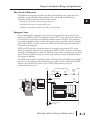
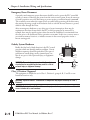
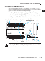

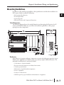
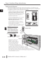
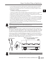

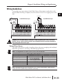

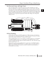
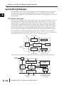


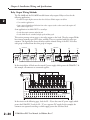


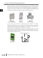
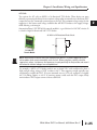
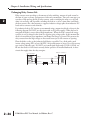

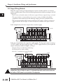


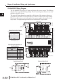

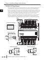
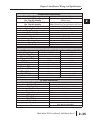


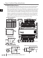
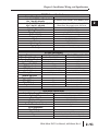


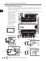

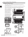
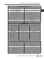


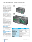
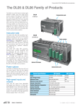
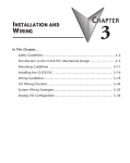


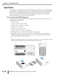
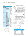
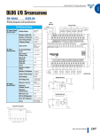

![English [2015v1]](http://vs1.manualzilla.com/store/data/005829431_1-1fdc30543d444fb0915a40c3aab945a8-150x150.png)