1
Ditch
User Manual
SD Drain Ditch User Manual - Distributed by Rust Sales, Inc. - 800-478-7801 - www.sddrain.com
V071415
2
Contents
Table of Contents ........................................................................................................................................ 2-3
Disclaimer .................................................................................................................................................... 4-5
Safety ............................................................................................................................................................. 6
EULA…………………………………………………………………………………………………………………… 7-8
Initial Program Setup ................................................................................................................................. 9-19
UTM Map ...................................................................................................................................................... 13
Quick Reference for Ditching ........................................................................................................................ 20
Quick Access Buttons Page 1 ....................................................................................................................... 21
Quick Access Buttons Overview
Zoom In/Zoom Out
Start Survey
Auto Enable/Disable
Minimize/Close
Next Page
Starting a Survey .......................................................................................................................................... 22
Start Survey/Stop Survey Buttons
Pause/Resume Survey Buttons
Automatic Control ......................................................................................................................................... 23
Auto Disable/Auto Enable
Minimize / Close Button ........................................................................................................................... 24-25
Next Page Button ................................................................................................................................... 15, 26
Quick Access Buttons Page 2 .................................................................................................................. 27-28
Settings Menu.......................................................................................................................................... 25-45
Program Menu ................................................................................................................................ 29-32
Profiles ..................................................................................................................................... 29
Machine .................................................................................................................................... 30
Program Settings ...................................................................................................................... 31
Backslope Settings ................................................................................................................... 32
GPS Devices Menu ......................................................................................................................... 33-38
GPS Device .............................................................................................................................. 33
BenchMarks ............................................................................................................................. 34
GPS Data ................................................................................................................................. 35
Satellites ................................................................................................................................... 36
GPS Settings ............................................................................................................................ 37
Emulator ................................................................................................................................... 38
DAC Menu ...................................................................................................................................... 39-40
DAC Device .............................................................................................................................. 39
DAC Data ................................................................................................................................. 40
Visual Menu .................................................................................................................................... 41-44
Graph ....................................................................................................................................... 41
Indicator Bar ........................................................................................................................ 42-43
Map .......................................................................................................................................... 44
Units ......................................................................................................................................... 45
UTM Zone Map ........................................................................................................................ 45
Project Menu ................................................................................................................................... 46-51
Ditch ......................................................................................................................................... 46
Boundary .................................................................................................................................. 47
Benchmarks ............................................................................................................................. 48
Elevation .................................................................................................................................. 49
SD Drain Ditch User Manual - Distributed by Rust Sales, Inc. - 800-478-7801 - www.sddrain.com
V071415
3
Contents
Spectral Image ......................................................................................................................... 50
New Project .............................................................................................................................. 51
Slope Settings .............................................................................................................................................. 52
Max Slope/Min Slope
Window Button ............................................................................................................................................. 53
Overhead Map
Side Profile
Back Profile
Terrain Map
Start Edit Button ........................................................................................................................................... 54
Cancel
Reset Graph
Undo
Preview
Done Editing
Google Earth Import ..................................................................................................................................... 55
SD Drain Ditch User Manual - Distributed by Rust Sales, Inc. - 800-478-7801 - www.sddrain.com
V071415
4
Disclaimer
•
While every effort has been made to ensure the accuracy of this document, Rust Sales, Inc.
and GK Technology assumes no responsibility for omissions or errors. Nor is any liability assumed for damages resulting from the use of information contained in this manual.
•
Rust Sales, Inc. and GK Technology shall not be responsible or liable for incidental or consequential damages; or a loss of anticipated benefits or profits; or work stoppage; or loss or impairment of data arising out of the use, or inability to use the control software or computer or
any other components.
•
Except as set forth above, Rust Sales, Inc. and GK Technology shall have no obligation or liability of any kind on account of any of its equipment and shall not be liable for special or consequential damages. Rust Sales, Inc. and GK Technology makes no other warranty, express or
implied, and specifically, Rust Sales, Inc. and GK Technology disclaims any implied warrant or
merchantability or fitness for a particular purpose. Some states or provinces do not permit limitations or exclusions of implied warranties or incidental or consequential damages, so the limitations or exclusions in this warranty may not apply.
•
As with all wireless and satellite signals, several factors may affect the availability and accuracy of wireless and satellite navigation and correction services. Therefore Rust Sales, Inc. and
GK Technology cannot guarantee the accuracy, integrity, continuity, or availability of these services and cannot guarantee the ability to use Rust Sales, Inc. and GK Technology’s systems
or products used as components of the systems, which rely upon the reception of these signals
or availability of these services. Rust Sales, Inc. and GK Technology accepts no responsibility
for the use of any of these signals or services for other than the stated purpose.
SD Drain Ditch User Manual - Distributed by Rust Sales, Inc. - 800-478-7801 - www.sddrain.com
V071415
5
Limited Warranty Statement
•
Rust Sales, Inc. and GK Technology warrants each product that it manufactures to be free from
defects in material and workmanship. This warranty is applicable only for the normal service life
expectancy of the product or components, not to exceed 12 consecutive months from the date
of the delivery to the original purchaser. This warranty coverage applies only to the original
owner and is not transferable. Under no circumstances will it cover any merchandise or components thereof, which in the opinion of the company has been subject to misuse, unauthorized
modification, alterations, improper installation, maintenance, an accident or if repairs have been
made with parts other than those obtained through Rust Sales, Inc.
•
SD Drain Packages can include products that are NOT manufactured by Rust Sales, Inc. and
GK Technologies These products carry their own respective warranty. Rust Sales, Inc. will
make warranty claims to these companies on behalf of the end user when a suspected warranty failure has occurred.
•
Our obligation under this warranty shall be limited to repairing at our facility or replacing, free of
charge to the original purchaser, any part that, in our judgment, shall show evidence of such
defect, provided further that such part be returned within 30 days from the date of failure to
Rust Sales, Inc. routed through the dealer from whom the purchase was made, transportation
charges prepaid. Proof of purchase must also accompany the returning defective part.
•
This warranty shall not be interpreted to render Rust Sales, Inc. and GK Technology liable for
injury or damages of any kind or nature to person or property. This warranty does not extend to
the loss of revenue, extra labor cost associated with downtime, substitute machinery, rental, or
for any other reason.
•
Except as set forth above, Rust Sales, Inc. and GK Technology shall have no obligation or liability of any kind on account of any of its equipment and shall not be liable for special or consequential damages. Rust Sales, Inc. and GK Technology makes no other warranty, express or
implied, and specifically, Rust Sales, Inc. and GK Technology disclaims any implied warrant or
merchantability or fitness for a particular purpose. Some states or provinces do not permit limitations or exclusions of implied warranties or incidental or consequential damages, so the limitations or exclusions in this warranty may not apply.
•
This warranty is subject to any existing conditions of supply which may directly affect our ability
to obtain materials or manufacture replacement parts.
•
No one is authorized to alter, modify or enlarge this warranty nor the exclusion, limitations, and
reservations.
SD Drain Ditch User Manual - Distributed by Rust Sales, Inc. - 800-478-7801 - www.sddrain.com
V071415
6
Safety
Safety Precaution-Remember, YOU are ultimately responsible for your safety
and the safety of those around you!
•
When working with or near these systems, please observe the following safety measures:
•
Be alert and aware of surroundings. Do not operate machinery or systems under the influence
of alcohol or an illegal substance. Remain in the operator’s position and be in complete control
at all times when systems are engaged.
•
Determine and maintain a safe working distance from other machinery, equipment, obstacles,
farm personnel, and people. The operator is responsible for proper disengagement of all
systems once safe working distance has been determined.
•
Know your software!! The DAC will only move as is called for by a controller package. The
operator is required to know how his software package functions and when it could possibly
send movement commands to the DAC controller.
Hydraulic Safety Requirements
•
Machine must be off, isolated, and stationary while installation and maintenance is being
performed. When disconnecting hydraulic hoses, be aware that the hydraulic oil within the
system may be hot and under high pressure. Caution must be exercised.
•
Any work carried out on the hydraulic systems must be performed in accordance with the
equipment manufacturer’s approved maintenance instructions. Rust Sales, Inc. recommends
that appropriate protective equipment be worn while working on the hydraulic system.
•
Warning: It is imperative that all hydraulic hoses are connected to the relevant components.
Failure to connect the hydraulic hoses correctly will cause damage to the system.
Electrical Safety Requirements
•
Do not reverse the power leads. Doing so will cause severe damage to the equipment.
•
Always check to make sure the power leads are connected to the correct polarity.
•
Ensure that the power cable is the last cable to be connected.
SD Drain Ditch User Manual - Distributed by Rust Sales, Inc. - 800-478-7801 - www.sddrain.com
V071415
7
EULA
Page 1 of 2
END-USER LICENSE AGREEMENT
FOR GK Technology, Inc. – SD Drain
IMPORTANT-READ CAREFULLY
This GK Technology, Inc. End-User License Agreement (“EULA”) is a legal agreement between you (either an individual or a single entity)
(“LICENSEE”) and GK Technology, Inc. for the software product(s) accompanying this EULA, which include(s) computer software and may include
"online" or electronic documentation, associated media, and printed materials (''SOFTWARE PRODUCT'').
By installing, copying, or otherwise using the SOFTWARE PRODUCT or any UPDATES (as defined below), you agree to be bound by the terms of
this EULA. If you do not agree to the terms of this EULA, do not install, copy, or use the SOFTWARE PRODUCT, and promptly return the entire
unused SOFTWARE PRODUCT to your place of purchase for a full refund.
In addition, by installing, copying, or otherwise using any updates or maintenance releases that you have received as part of the SOFTWARE
PRODUCT (''UPDATES''), you agree to be bound by the additional license terms that accompany such UPDATES. If you do not agree to the additional license terms that accompanies such UPDATES, you may not install, copy, or use such UPDATES.
SOFTWARE PRODUCT LICENSE
Copyright laws and international copyright treaties, as well as other intellectual property laws and treaties protect the SOFTWARE PRODUCT. The
SOFTWARE PRODUCT is licensed, not sold. The SOFTWARE PRODUCT consists of product documentation, sample applications, tools and utilities, and miscellaneous technical information, (individually identified as "COMPONENT" and collectively as "COMPONENTS"). The rights regarding
the COMPONENTS of the SOFTWARE PRODUCT are described below unless otherwise indicated.
1. GRANT OF LICENSE. GK Technology, Inc. grants to you as an individual a personal, nonexclusive, nontransferable license to make and use
copies of the SOFTWARE PRODUCT in the manner provided below. If you are an entity, GK Technology, Inc. grants to you the right to designate
one individual within your organization to have the right to use the SOFTWARE PRODUCT in the manner provided below. You may use this SOFTWARE PRODUCT on a networked system provided that the number of SOFTWARE PRODUCT users on the network at one time does not exceed
the number of licensed copy(ies)of the SOFTWARE PRODUCT. GK Technology, Inc. retains title and ownership of the SOFTWARE PRODUCT or
any copy.
2. COPY RESTRICTIONS. This SOFTWARE PRODUCT and the accompanying COMPONENTS are copyrighted. Unauthorized copying of the
SOFTWARE PRODUCT, including any part of the SOFTWARE PRODUCT that has been modified, merged, or included with other software, or of
the COMPONENTS is expressly forbidden. You may be held legally responsible for any copyright infringement that is caused or encouraged by
your failure to abide by the terms of this EULA. Subject to these restrictions, you may make one (1) copy of the SOFTWARE PRODUCT solely for
backup purposes. You must reproduce and include the copyright notice on the backup copy. You may not copy the printed materials accompanying
the SOFTWARE PRODUCT, or print multiple copies of any user documentation.
3. USE RESTRICTIONS. As the LICENSEE, you may use the SOFTWARE PRODUCT on one computer at one time and place. You may not distribute copies of the SOFTWARE PRODUCT to others. You may not modify, adapt, translate, reverse engineer, decompile, disassemble, or create
derivative works based on the SOFTWARE PRODUCT. You may not modify, adapt, translate, or create derivative works based on the written materials without the prior written consent of GK Technology, Inc.
4. TRANSFER RESTRICTIONS. This SOFTWARE PRODUCT is licensed only to your, the LICENSEE, and may not be transferred to anyone
without the prior written consent of GK Technology, Inc. Any unauthorized transferee of the SOFTWARE PRODUCT shall be bound by the terms
and conditions of this EULA. Enabling others to use your registration code(s) or serial number(s) is strictly prohibited. In no event may you transfer,
assign, rent, lease, sell, or otherwise dispose of the SOFTWARE PRODUCT on a temporary or permanent basis except as expressly provided herein.
5. TERMINATION. This EULA is effective until terminated. This EULA will terminate automatically without notice from GK Technology, Inc. if you
fail to comply with any provision of this EULA. Upon termination you shall destroy the written materials and all copies of the SOFTWARE PRODUCT
previously licensed to you.
6. UPDATES AND UPGRADES. GK Technology, Inc. may create, from time to time, updated versions of the SOFTWARE PRODUCT. At its option, GK Technology, Inc. will make such updates available to the LICENSEE. If the SOFTWARE PRODUCT is being licensed to you as an update
or upgrade to a SOFTWARE PRODUCT previously licensed to you, you must destroy the SOFTWARE PRODUCT previously licensed to you, including any copies resident on your hard-disk drive(s) within thirty (30) days of the purchase of the license to use the update or upgrade.
7. SUPPORT SERVICES. GK Technology, Inc. may provide you with support services related to the SOFTWARE PRODUCT ("Support Services").
Use of Support Services is governed by the GK Technology, Inc. policies and programs described in the user manual, "online" documentation, and/
or GK Technology, Inc. provided materials. Any supplemental items provided to you as part of the Support Services shall be considered part of the
SOFTWARE PRODUCT and subject to the terms and conditions of this EULA. With respect to technical information you provide to GK Technology,
Inc. as part of the Support Services, GK Technology, Inc. may use such information for its business purposes, including for product support and
development. GK Technology, Inc. will not utilize such technical information in a form that personally identifies you.
8. COPYRIGHT. All title and copyrights in and to the SOFTWARE PRODUCT, the accompanying printed materials, and any copies of the SOFTWARE PRODUCT, are owned by GK Technology, Inc. The SOFTWARE PRODUCT is protected by copyright laws and international treaty provisions. Therefore, you must treat the SOFTWARE PRODUCT like any other copyrighted material except that you may either (a) make one copy of
the SOFTWARE PRODUCT solely for backup or archival purposes, or (b) install the SOFTWARE PRODUCT on a single computer provided you
keep the original solely for backup or archival purposes. You may not copy the printed materials accompanying the SOFTWARE PRODUCT.
SD Drain Ditch User Manual - Distributed by Rust Sales, Inc. - 800-478-7801 - www.sddrain.com
V071415
8
EULA
Page 2 of 2
9. UPDATE LICENSE TERMS. Additional license terms may accompany UPDATES. By installing, copying, or otherwise using any UPDATE, you
agree to be bound by the terms accompanying each such UPDATE. If you do not agree to the additional EULA terms accompanying such UPDATES, do not install, copy, or otherwise use such UPDATES.
10. EXPORT RESTRICTIONS. You agree that neither you nor your customers intend to or will, directly or indirectly, export or transmit the SOFTWARE PRODUCT or related documentation and technical data (or any part thereof), or your software application product to any country to which
such export or transmission is restricted by any applicable U.S. regulation or statute, without the prior written consent, if required, of the Bureau of
Export Administration of the U.S. Department of Commerce, or such other governmental entity as may have jurisdiction over such export or transmission.
11. U.S. GOVERNMENT RESTRICTED RIGHTS. The SOFTWARE PRODUCT and documentation are provided with RESTRICTED RIGHTS.
Use, duplication, or disclosure by the Government is subject to restrictions as set forth in subparagraph (c)(1)(ii) of The Rights in Technical Data and
Computer Software clause at DFARS 252.227-7013 or subparagraphs (c)(1) and (2) of the Commercial Computer Software-Restricted Rights at 48
CFR 52.227-19, as applicable. Manufacturer is GK Technology, Inc., 204 5th Street East, Halstad, MN 56548.
DISCLAIMER OF WARRANTY
NO WARRANTIES.
THE SOFTWARE PRODUCT IS PROVIDED "AS IS" WITHOUT WARRANTY OF ANY KIND. TO THE MAXIMUM EXTENT PERMITTED BY APPLICABLE LAW, GK TECHNOLOGY, INC. AND ITS SUPPLIERS DISCLAIM ALL WARRANTIES, EITHER EXPRESS OR IMPLIED, INCLUDING,
BUT NOT LIMITED TO, IMPLIED WARRANTIES OF MERCHANTABILITY AND FITNESS FOR A PARTICULAR PURPOSE AND ANY WARRANTY AGAINST INFRINGEMENT, WITH REGARD TO THE SOFTWARE PRODUCT. THIS LIMITED WARRANTY GIVES YOU SPECIFIC LEGAL
RIGHTS. YOU MAY HAVE OTHERS, WHICH VARY FROM STATE/JURISDICTION TO STATE/JURISDICTION.
CUSTOMER REMEDIES
GK TECHNOLOGY, INC'S ENTIRE LIABILITY AND YOUR EXCLUSIVE REMEDY SHALL NOT EXCEED THE PRICE PAID FOR THE SOFTWARE
PRODUCT.
NO LIABILITY FOR DAMAGES
TO THE MAXIMUM EXTENT PERMITTED BY APPLICABLE LAW, IN NO EVENT SHALL GK TECHNOLOGY, INC. OR ITS SUPPLIERS BE LIABLE FOR ANY DAMAGES WHATSOEVER (INCLUDING, WITHOUT LIMITATION, DAMAGES FOR LOSS OF BUSINESS PROFITS, BUSINESS
INTERRUPTION, LOSS OF BUSINESS INFORMATION, OR ANY OTHER PECUNIARY LOSS) ARISING OUT OF THE USE OF OR INABILITY TO
USE THIS GK TECHNOLOGY, INC. PRODUCT, EVEN IF GK TECHNOLOGY, INC. HAS BEEN ADVISED OF THE POSSIBILITY OF SUCH DAMAGES. BECAUSE SOME STATES/JURISDICTIONS DO NOT ALLOW THE EXCLUSION OR LIMITATION OF LIABILITY FOR CONSEQUENTIAL
OR INCIDENTAL DAMAGES, THE ABOVE LIMITATION MAY NOT APPLY TO YOU.
MISCELLANEOUS. This Disclaimer and Limitation of Liability are governed by the laws of the State of Minnesota. If this product was acquired
outside the United States, then local law may apply.
Should you have any questions concerning this EULA, or if you desire to contact GK Technology, Inc. for any reason, please contact in writing:
GK Technology Inc.
204 5th Street East
Halstad, MN 56548
SD Drain Ditch User Manual - Distributed by Rust Sales, Inc. - 800-478-7801 - www.sddrain.com
V071415
9
Initial Program Set Up
Setting GPS Receiver Output Data
1
Before starting SD Drain the GPS receiver being used must be set to
output specific parameters. The next few pages show how to set
parameters outputs for different GPS receiver brands.
GPS Settings that need to be set before connecting to SD Drain:
Baud Rate
Set at 57600 or 38400 (57600 is preferred)
NEMA Strings 3 Required
GGA — 10Hz or 5Hz (only use 5Hz if 10Hz is unavailable)
GSA — 1Hz
RCM or VTG (RCM is preferred) - 1Hz
John Deere 3000/ITC se ngs for SD Drain
Plug the 3000 or ITC Globe to a John Deere screen 2630, 2600, 1800, command center, or Brown Box.
Go to the Globe se#ngs on the Globe
Change the Baud Rate to 57600 (38400 for ITC)
Set the HZ to 10 (5 for ITC)
Turn GGA, GSA & RCM “ON” (Make Sure ALL the rest are OFF)
Turn TCM (Tilt Control Module) OFF
Go back to home page and confirm the globe is ge#ng RTK GPS. (Change tower network ID’s if you need too)
Verify RTK GPS before powering down.
Power the John Deere screen completely off.
Connect Globe to SD Drain Cables and turn machine on.
SD Drain Ditch User Manual - Distributed by Rust Sales, Inc. - 800-478-7801 - www.sddrain.com
V071415
10
Initial Program Set Up
1
Setting GPS Receiver Output Data
Trimble (262/252/372) Settings
Double Click on Ag Remote on the computer.
Select File and Connect then click OK.
Touch the right arrow until it displays configuration.
Touch the Down arrow until it displays GPS Config
Touch the down arrow until it displays position rate
Make sure it displays 10 HZ (if it does not change it)
Touch the up arrow till GPS Config
Touch the right arrow until it shows Port A
Touch the Down arrow until it shows NMEA 1
Turn GGA , GSA and RCM messages on and touch the enter button
Touch the down button till it gets to NMEA output rate
Change the NMEA output to ASAP
Touch the enter button
Touch the up arrow till it shows Port A in/out
Change the screen to look like this
I - TSIP - 38.4k
O - 8N1 - NMEA - 38.4K
Touch the enter button and that will disconnect the GPS from AG remote. Exit Ag remote and start
SD Drain
Note:
Confirm RTK is working on the Trimble receiver before changing settings. Change tower networks
if needed.
Confirm GGA, GSA and RCM are the only NMEA messages that is on in NMEA 1,2 & 3 ( ON = All
Capital letters in Port A Config)
SD Drain Ditch User Manual - Distributed by Rust Sales, Inc. - 800-478-7801 - www.sddrain.com
V071415
11
Initial Program Set Up
The initial program setup has to be done once before using the SD Drain Ditch
package. This initial setup is necessary to define user and equipment parameters and ensure proper connectivity to the gps receiver and automatic machine
control modules.
Power on Control Computer
2
Locate the control computers
power rocker switch behind the
lower right back of the computer.
Press and hold the rocker power switch for 10 seconds to turn the computer on. When the
computer boots to the Start Screen double tap on the SD Drain icon.
Double Tap the SD Drain icon to start the program.
SD Drain Ditch User Manual - Distributed by Rust Sales, Inc. - 800-478-7801 - www.sddrain.com
V071415
12
Initial Program Set Up
EULA and Disclaimer
3
After the SD Icon was double tapped the first screen that appears is
the Terms of Use Screen. First tap to read the EULA and then
Scroll down to read the disclaimer and then tap to Agree or Do NOT
Agree.
Note, Every time the program is started the user must tap
Agree or Do NOT Agree on the Terms of User screen
SD Drain Ditch User Manual - Distributed by Rust Sales, Inc. - 800-478-7801 - www.sddrain.com
V071415
13
Initial Program Set Up
4
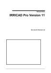
UTM Zone Setup
The first screen that appears after tapping the Agree box from the Disclaimer page is the is
shown below. Set the UTM Zone where SD Drain will be operating in. If you are not sure
what zone to enter, do a internet search asking “what UTM zone am I in?”
Press “-” or “+” to set the zone. Once set, it will automatically be saved
UTM—Acronym for “Universal Transverse Mercator”. A projected coordinate system divides
the world into 60 north and south zones, 6 degrees wide.This is what everything is projected in
within the software. Being in the correct UTM zone is critical to ensure the location is accurate.
USA UTM ZONES
Canada UTM ZONES
SD Drain Ditch User Manual - Distributed by Rust Sales, Inc. - 800-478-7801 - www.sddrain.com
V071415
14
Initial Program Set Up
Input User Information
5
Follow instructions below to enter the appropriate information. You must load a
project to advance to the next screen.
Data Path; only change if
you wish to save a project to
a file other than the default
file.
Grower; Add grower using
the “+” button or choose
Grower using dropdown
menu.
Farm; Add Farm using the
“+” button or choose Farm
using dropdown menu.
Field; Add Field using the
“+” button or choose Field
using dropdown menu.
Note: it is critical to label each
field you are in for
future reference.
Select one of these three options:
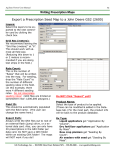
Load New Project w/ Files; Use this section if you have a background image or predesigned map to
load with the new project. A layers screen will pop up showing the selections. Change or add the correct files to bring them to the working screen. Select Continue to bring up the working screen of SD
Drain.
Load Selected Project; if you have already worked on this field.
Load New Project; if this is the start of a new field without extra files.
Projects; displays all created projects for the field.
To load a previous project, highlight the desired project and press the Load Previous Project button.
To delete an old, unwanted project, highlight it in the project list and click the trash can. You will be
prompted to confirm you want to send the project to the trash can. Select Yes to confirm and No to
cancel.
SD Drain Ditch User Manual - Distributed by Rust Sales, Inc. - 800-478-7801 - www.sddrain.com
V071415
15
Initial Program Set Up
Machine Control Settings
6
The next few steps will have default settings for most sections. It is recommended to only change the default settings after using the program for a period
of time. Tap on the “Settings” icon to open. If the “Settings” icon is not visible,
tap on the “Next” icon until the “Settings” icon is visible.
SD Drain Ditch User Manual - Distributed by Rust Sales, Inc. - 800-478-7801 - www.sddrain.com
V071415
16
Initial Program Set Up
Settings Page
7
After tapping the “Settings” icon tab you will see the settings screen. The top row
is the master TABS row. The second row is the sub TAB row. The sub TAB row
changes content and color depending on which selection is highlighted in the master TAB row.
Select the GPS master tab first and proceed to the next page of this manual.
Master TAB Row
Sub TAB Row
SD Drain Ditch User Manual - Distributed by Rust Sales, Inc. - 800-478-7801 - www.sddrain.com
V071415
17
Initial Program Set Up
GPS Receiver Settings
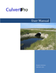
8
After selecting the red GPS master tab you will see six GPS red sub tabs.
SD
Drain detects the GPS receiver and sets the GPS parameters automatically as required by SD Drain. Follow the instructions below to detect and start the GPS receiver.
Be sure all cables are connected from the GPS receiver to control computer
first.
Select the GPS tab
Select the proper
GPS Device
Select Detect
After GPS
has been
Detected
Select Start
After you see that GPS is detected in the status section and “Start” has been tapped,
the next page to set up the DAC auto controller.
SD Drain Ditch User Manual - Distributed by Rust Sales, Inc. - 800-478-7801 - www.sddrain.com
Proceed to
V071415
18
Initial Program Set Up
DAC Settings
9
The DAC module controls the tractors hydraulic SCVs (Selectable control valves ).
or can be connected to external hydraulic valves. See the 2015 DAC installation
manual for proper tractor connection instructions.
Select the DAC tab
Select DAC Device
Select the Detect tab
When DAC DETECTED appears in the status screen proceed to the next page to enter Machine
settings.
SD Drain Ditch User Manual - Distributed by Rust Sales, Inc. - 800-478-7801 - www.sddrain.com
V071415
19
Initial Program Set Up
Machine (Scraper) Settings
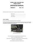
10
Input the required settings for the Machine (Scraper) you are working with.
Note the instruction box to the right. Accuracy of these inputs is important.
Select Program
Tab
Select Machine
Tab
Insert accurate
values into each
fields or select the
calculator to auto
calculate the blade
to ground and follow the instructions
in the pop up boxes
If assistance is
needed, see page
24 for more info.
Definitions:
Blade Width:
The width of the scraper blade in inches.
Blade to Ground:
The Distance from the scraper blade to flat ground in inches (have the blade
positioned all the way up). Touch the Calculator to read automatically. GPS is
needed.
GPS Globe Height: The height from the GPS Globe to the ground in inches (position blade on the
ground).
GPS Offset Fore(+)/Aft(-):
The distance, in inches, from the GPS globe to the center of the blade.
GPS Offset Left(+)/Right(-): The distance, in inches, from the GPS globe to the center of the blade.
After all values are filled in this will finish the initial setup. You may now start a ditch.
SD Drain Ditch User Manual - Distributed by Rust Sales, Inc. - 800-478-7801 - www.sddrain.com
V071415
20
Quick Reference Guide—Ditching
Start at the top of the ditch with the blade all the way up.
Select Start Survey
Drive the ditch, follow exactly where you want the ditch to
be.
Select Stop Survey at the end of the ditch.
Confirm Auto Enable is on.
Cut the ditch.
When finished, start a new ditch by selecting Start Survey.
You will be asked if you want to save the ditch. Select YES if you want it saved or No if
you would like it discarded.
SD Drain Ditch User Manual - Distributed by Rust Sales, Inc. - 800-478-7801 - www.sddrain.com
V071415
21
Quick Access Buttons—Page 1
Quick Access Buttons Page 1 Overview
Zoom In:
Tap this button and then touch on the screen where you would like to zoom in on
(This will re-center the image to wherever you click and zoom in on that area).
Zoom Out:
Tap this button and then touch on the screen where you would like to zoom out
on. This will re-center the image to wherever you click and zoom out on that
area.
Start Survey:
This button allows the user to Start and Stop Surveys. How to survey will be
explained on page 10
Auto Enable/Disable:
This button will allow the user to use Automatic control of the implement’s
hydraulics. During a survey, this will also pause and resume the survey. See
page 11 for more information.
Minimize/Close:
This button allows closing and minimizing the program. See pages 12-13 for
more information.
Next Page:
Touch this to acquire access to the next page of quick access controls.
SD Drain Ditch User Manual - Distributed by Rust Sales, Inc. - 800-478-7801 - www.sddrain.com
V071415
22
Starting a Survey
Start Survey:
Touch the Start Survey button when you are at the start of the ditch with the
blade up. Drive toward the opposite end of the ditch, following the contour of
the ditch and staying in the bottom.
Stop Survey:
When you get done with the survey, touch the Stop Survey button. This will
finish the survey and design the ditch. To start a new ditch in this project, just
touch the Start Survey button, repeating the above steps.
Pause Survey:
The Pause Survey button can be used to pause the survey if you need to go
around a pole, culvert, water, etc.
Resume Survey:
To resume the current survey, select Resume Survey, which will restart the
survey from the current point. Remember to leave the blade all the way up
during the entire survey.
SD Drain Ditch User Manual - Distributed by Rust Sales, Inc. - 800-478-7801 - www.sddrain.com
V071415
23
Automatic Control
Auto Buttons
The Auto button will allow you to run automatic control of the hydraulics.
Touch button to turn off and touch to turn automatics on.
The Auto Disable will be red if off
Green is Auto Enable is on
Out of Range means Auto Enable is on but the user is out of the designed area
and not recording work done and SD will not be controlling the blade.
SD Drain Ditch User Manual - Distributed by Rust Sales, Inc. - 800-478-7801 - www.sddrain.com
V071415
24
Minimize / Close Button
Close and Shutdown Buttons
Touch Close Program to close out of SD Drain. This will save all the work that has been done.
Touch Shutdown to close the program and
shut down the computer.
You will have to select Yes or No to
confirm.
SD Drain Ditch User Manual - Distributed by Rust Sales, Inc. - 800-478-7801 - www.sddrain.com
V071415
25
Minimize / Close Button
Minimize Button
Touch Minimize button to minimize SD Drain and get back to the main screen of the
computer.
To bring back up SD Drain, touch the SD Drain logo on the bottom of the screen.
SD Drain Ditch User Manual - Distributed by Rust Sales, Inc. - 800-478-7801 - www.sddrain.com
V071415
26
Go to Next Page
Next Page Button
Touch the Next Page button on the bottom right to get another set of buttons.
SD Drain Ditch User Manual - Distributed by Rust Sales, Inc. - 800-478-7801 - www.sddrain.com
V071415
27
Quick Access Buttons—Page 2
Quick Access Buttons Page 2 Overview
SD Drain Ditch User Manual - Distributed by Rust Sales, Inc. - 800-478-7801 - www.sddrain.com
V071415
28
Quick Access Buttons—Page 2
Settings Button
Press Settings button on top to get into the expanded drop down Settings Menu
SD Drain Ditch User Manual - Distributed by Rust Sales, Inc. - 800-478-7801 - www.sddrain.com
V071415
29
Settings—Program Menu
Program Menu—Profiles
Definitions:
Minimum Slope:
The desired minimum slope of each cut in percent.
Minimum Increment: The amount to adjust either up/down the minimum slope on the +- buttons
on the main slider.
Maximum Slope:
The desired maximum slope of each cut in percent
Maximum Scrape:
The max depth of the scraper cut in inches
Minimum Cut Depth: The minimum desired amount of soil to cut from the grade line in inches. This
value is calculated for all cuts beyond the ditch outlet.
Large Nudge:
The amount to nudge the “large nudge factor” in tenths
Small Nudge:
The amount to nudge the “small nudge factor” in tenths
Laser Level Off:
Turn this On to do a straight grade like a laser would
SD Drain Ditch User Manual - Distributed by Rust Sales, Inc. - 800-478-7801 - www.sddrain.com
V071415
30
Settings—Program Menu
Program Menu—Machine
Select the
calculator to
auto
calculate the
blade to the
ground
setting.
Follow these
instructions.
Definitions:
Blade Width:
Blade to Ground:
The width of the scraper blade in inches.
The Distance from the scraper blade to level ground in inches (have the blade
positioned all the way up). Touch the Calculator to read automatically. GPS is
needed.
GPS Globe Height: The height from the GPS Globe to the ground in inches (position blade on the
ground).
GPS Offset Fore(+)/Aft(-):
The distance, in inches, from the GPS globe to the center of the blade.
GPS Offset Left(+)/Right(-):
The distance, in inches, from the GPS globe to the center of the blade.
SD Drain Ditch User Manual - Distributed by Rust Sales, Inc. - 800-478-7801 - www.sddrain.com
V071415
31
Settings—Program Menu
Program Menu—Program Settings
* Leave the defaults alone unless directed by a technician.
SD Drain Ditch User Manual - Distributed by Rust Sales, Inc. - 800-478-7801 - www.sddrain.com
V071415
32
Settings—Program Menu
Program Menu—Backslope Settings
Backsloping On: Touch icon, green check is on, red x is off.
Definitions:
Lateral Ditch: A lateral Ditch is usually the smaller ditch that flows into a main ditch.
Ditch Width:
The width of the bottom of the ditch
Backslope Width: The distance from the bottom of the ditch to the distance in which you
want to backslope.
Backslope:
The ratio of the backslope cut (e.g, 1:3 where 1 is the rise and 3 is the run)
Main Ditch:
This is the typically larger ditch that will receive water from the smaller, lateral
ditches.
Ditch Width:
The width of the bottom of the ditch
Back Slope Width: The distance from the bottom of the ditch to the distance in which you
want to backslope
Backslope:
The ratio of the backslope cut( e.g, 1:3 where 1 is the rise and 3 is the run)
SD Drain Ditch User Manual - Distributed by Rust Sales, Inc. - 800-478-7801 - www.sddrain.com
V071415
33
Settings—GPS Menu
GPS Menu—GPS Device
To set up GPS, select Device Name and select the Detect button. This should automatically select
the COM port that the GPS is coming into. Then select Start button to start using the GPS.
GPS Settings that need to be set before connecting to SD Drain:
• Baud Rate
Set at 57600 or 38400 (57600 is preferred)
• NEMA Strings 3 Required
GGA — 10Hz or 5Hz (only use 5Hz if 10Hz is unavailable)
GSA — 1Hz
RCM or VTG (RCM is preferred) - 1Hz
SD Drain Ditch User Manual - Distributed by Rust Sales, Inc. - 800-478-7801 - www.sddrain.com
V071415
34
Settings—GPS Menu
GPS Menu — BenchMarks
BenchMarks are for repeatability of RTK GPS. It is a real world known location that can be accessed
at any time based on the coordinates. BenchMarks are very important for any brand RTK for
repeatability from day to week to year.
BenchMarks should be placed at locations easily about to accessing in the future (e.g. above a
culvert, corner post).
You need to have the GPS Globe Height and Blade to ground set correctly.
The best time to capture a BenchMark is to take it at night and load it up before moving the implement
in the morning (the blade must be all the way up at all times to avoid settling).
SD Drain Ditch User Manual - Distributed by Rust Sales, Inc. - 800-478-7801 - www.sddrain.com
V071415
35
Settings—GPS Menu
GPS Menu—GPS Data
If you select GPS Data, this will show you the quality that you have at the current time.
If GPS is ever lost due to bad satellites, trees, broken cables/antennas, a red flashing screen will
come up on the home page indicating you have bad signal.
SD Drain Ditch User Manual - Distributed by Rust Sales, Inc. - 800-478-7801 - www.sddrain.com
V071415
36
Settings—GPS Menu
GPS Menu—Satellites
This shows the current satellites that are being used.
SD Drain Ditch User Manual - Distributed by Rust Sales, Inc. - 800-478-7801 - www.sddrain.com
V071415
37
Settings—GPS Menu
GPS Menu—GPS Settings
• Leave defaults alone unless directed by a technician.
Definitions:
VDOP:
Diff Age:
Fix Quality:
Hor. Error:
Vert. Error:
The Vertical Dilution of Precision. Default is 3
Differential Age is the age of the corrections in seconds that the GPS was received
from the base station.
Quality of the GPS needed to work. RTK Fixed should always be used; all others will
be less accurate. RTK Float would be for corrected GPS but not as accurate as RTK.
GPS fix is for WAAS GPS. Simulated- used in office or demo.
Horizontal error of the GPS messages. Default is .1
Vertical error of the GPS messages. Default is .1
SD Drain Ditch User Manual - Distributed by Rust Sales, Inc. - 800-478-7801 - www.sddrain.com
V071415
38
Settings—GPS Menu
GPS Menu—Emulator
The Emulator is for playing back runs.
SD Drain Ditch User Manual - Distributed by Rust Sales, Inc. - 800-478-7801 - www.sddrain.com
V071415
39
Settings—DAC Menu
DAC Menu—DAC Device
Select Detect to find the DAC 7000 on the COM port that it is plugged into.
For tuning, select Open DAC Settings.
*See your 2015 DAC Installation & Tuning Manual for more instructions.
SD Drain Ditch User Manual - Distributed by Rust Sales, Inc. - 800-478-7801 - www.sddrain.com
V071415
40
Settings—DAC Menu
DAC Menu—DAC Data
Shows pitch and roll information if a slope sensor is connected.
SD Drain Ditch User Manual - Distributed by Rust Sales, Inc. - 800-478-7801 - www.sddrain.com
V071415
41
Settings—Visual Menu
Visual Menu—Graph
Definitions:
Colors that can be chosen for the side view cutting screen.
Show Graph Legend:
Show Calculated Gradeline:
Line Width:
Indicator Size:
Ability to take off the legend on the side view cutting screen
Shows the next cut for the gradeline
Size of the grade line
Size of the indicator on the Graph screen
SD Drain Ditch User Manual - Distributed by Rust Sales, Inc. - 800-478-7801 - www.sddrain.com
V071415
42
Settings—Visual Menu
Visual Menu—Indicator Bar
The vertical side bar on the main screen will allow the user to nudge up/down (+/-) from the proposed
cut. See next page for more info
The Horizonal top bar is for steering guidance side to side
If the user does not want to view the horizontal or vertical bar on the main screen, make sure the
check mark is not checked in the “Horizontal Bar Visible” box (same with Vertical Bar Visible).
SD Drain Ditch User Manual - Distributed by Rust Sales, Inc. - 800-478-7801 - www.sddrain.com
V071415
43
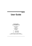
Settings—Visual Menu
The Vertical Bar has been used to bring this line up 0.16 feet in this example. This shows that the
user can move the line up for down to cut less or more to get the desired depth of this ditch.
This can be touched to move the grade line 0.2 feet down.
This can be touched to move the grade line 0.1 feet down.
The center shows where the blade should be.
This can be touched to move the grade line 0.1 feet up.
This can be touched to move the grade line 0.2 feet up
SD Drain Ditch User Manual - Distributed by Rust Sales, Inc. - 800-478-7801 - www.sddrain.com
V071415
44
Settings—Visual Menu
Visual Menu—Map
Definitions:
Survey Lines: These are shown in the Overhead Map
Current Color:
Color that the current ditch is being worked on
Selected Color:
Color that the current ditch is selected
Saved Color:
Color of all the saved ditches in the overhead map
Width:
Size of the ditch in the overhead map screen
GPS Symbol: Size and color the implement should be on the screen.
SD Drain Ditch User Manual - Distributed by Rust Sales, Inc. - 800-478-7801 - www.sddrain.com
V071415
45
Settings—Visual Menu
Visual Menu—Units
Show Position In:
UTM;
Decimal Degrees;
Degrees, Decimal Minute;
Degrees, Minute, Seconds
Select UTM Zone if that is
selected.
Show Speed in:
Miles Per Hour
Show Altitude in:
Feet or Inches or Meters
SD Drain Ditch User Manual - Distributed by Rust Sales, Inc. - 800-478-7801 - www.sddrain.com
V071415
46
Settings—Project Menu
Project—Ditches
•
This is where you would change the files used for Ditch mapping.
* Note: These files are imported data files from previously designed projects in
Ag Data Mapping Solution
SD Drain Ditch User Manual - Distributed by Rust Sales, Inc. - 800-478-7801 - www.sddrain.com
V071415
47
Settings—Project Menu
Project—Boundary
•
This is where you would change the files used for Boundary mapping.
* Note: These files are imported data files from previously designed projects in
Ag Data Mapping Solution
SD Drain Ditch User Manual - Distributed by Rust Sales, Inc. - 800-478-7801 - www.sddrain.com
V071415
48
Settings—Project Menu
Project—Benchmarks
•
This is where you would change the files used for Benchmarks
* Note: These files are imported data files from previously designed projects in
Ag Data Mapping Solution
SD Drain Ditch User Manual - Distributed by Rust Sales, Inc. - 800-478-7801 - www.sddrain.com
V071415
49
Settings—Project Menu
Project—Elevation
•
This is where you would change the files used for Elevation mapping.
•
Note: These files are imported data files from previously designed projects
in Ag Data Mapping Solution
This would be a elevation map showing topography
•
SD Drain Ditch User Manual - Distributed by Rust Sales, Inc. - 800-478-7801 - www.sddrain.com
V071415
50
Settings—Project Menu
Project—Spectral Image
Backround images or Spectral Images can be added here. Put Desired image in the correct Grower, Farm
Field in the folder C:Drive– GKData-Grower-Farm-Field
Sample of image- RSI.bmp & RSI.bpw
Contact your Dealer for additional information.
SD Drain Ditch User Manual - Distributed by Rust Sales, Inc. - 800-478-7801 - www.sddrain.com
V071415
51
Settings—Project Menu
Project—New Project
To Start a new
Project. Select
New Project and
select Yes
SD Drain Ditch User Manual - Distributed by Rust Sales, Inc. - 800-478-7801 - www.sddrain.com
V071415
52
Slope Settings
Slope Settings
Change these before cutting the dirt.
Definitions:
Min Slope:
Touch the Min Slope Button, then:
Touch + to increase Minimum Slope
Touch – to decrease Minimum Slope
Max Slope:
Touch the Max Slope Button, then:
Touch + to increase Max Slope
Touch – to decrease Max Slope
Select Next Page button to move to the next set of quick access buttons.
SD Drain Ditch User Manual - Distributed by Rust Sales, Inc. - 800-478-7801 - www.sddrain.com
V071415
53
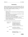
Window Button
Window Button:
Touch the window button and the 4 options come up
Window Button
Overhead Map:
Turn this on or off to show the whole
field/background map.
Back Profile:
This graph will
show how the
backslope feature
is working. This will
show a cross sec-
Side Profile:
Touch the button to
turn this off or on. This
will show the cut screen
Terrain Map:
A Map designed in 3D. This will only work if you
imported survey data for this job.
Overhead map
Side Profile
Back Profile
SD Drain Ditch User Manual - Distributed by Rust Sales, Inc. - 800-478-7801 - www.sddrain.com
V071415
54
Start Edit Button
Editing a Survey
Start Edit: This feature will allow you to remove points from the survey line. This will
help if you accidently drove too far or over a big rock, etc.
To Edit , Select by Point and select a specific point on the graph or Select by Area and select a
area that should be removed.
Definitions:
Cancel:
Reset Graph:
Undo:
Preview:
Done Editing:
This will cancel any edit.
This will reset the graph to what it was without editing anything.
This will undo the last points you edited.
This will Show you what the graph will look like with the editing that was done.
This will save the points you removed and use the new graph for the cutting line.
SD Drain Ditch User Manual - Distributed by Rust Sales, Inc. - 800-478-7801 - www.sddrain.com
V071415
55
Google Earth Import
To take the ditches that have been cut and apply them over a
google earth image. Go to C Drive/ GKdata/ Grower/ Farm/ Field
Select the Drainage project and take the gkml file and change the
extension to kml and then open it in google earth.
SD Drain Ditch User Manual - Distributed by Rust Sales, Inc. - 800-478-7801 - www.sddrain.com
V071415
56
Quick Access Buttons Page 3
Show will allow the user to show a previously hidden ditch line. Select
Show and select the line that you would like to show on the overhead
view again.
Hide button- Touch the ditch on the screen that you would like to hide
from the overhead view and then touch the hide button to hide the
current ditch
Capture Graph- This will allow you to save the current side profile of
any specific ditch to be able to view it later. It is just a screenshot of
the side view. The captured graph will be stored in the c drive-gkdata
-grower– farm-field-Profile
Select Next to go to the first set of quick access buttons.
SD Drain Ditch User Manual - Distributed by Rust Sales, Inc. - 800-478-7801 - www.sddrain.com
V071415