1
A-28
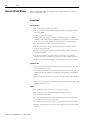
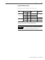
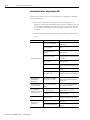
Parameter List
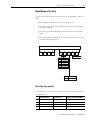
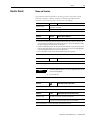
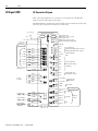
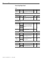
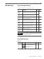
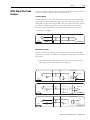
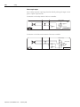
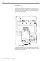
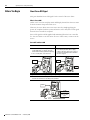
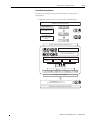
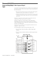
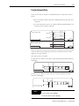
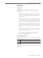
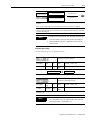
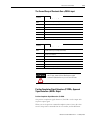
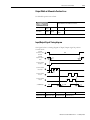
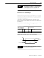
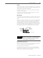
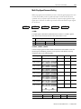
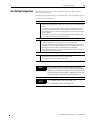
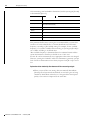
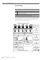
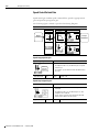
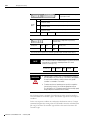
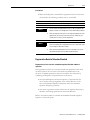
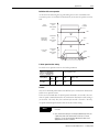
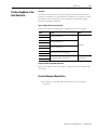
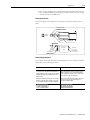
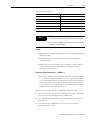
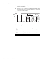
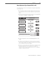
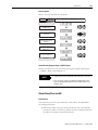
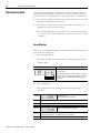
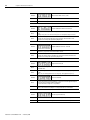
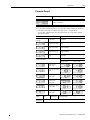
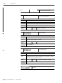
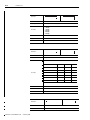
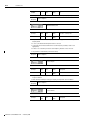
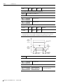
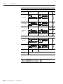
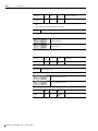
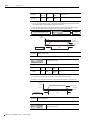
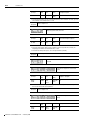
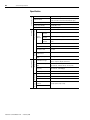
When this signal is input, the position error is cleared to ‘0’ so that, if no more position command
pulses are input, the moor can be halted at current condition. The position error clear(PCLR) input
signal is input at pins (15,16) of CN1.
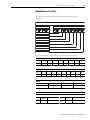
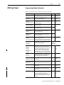
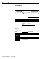
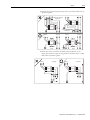
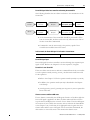
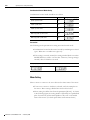
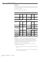
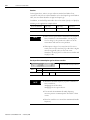
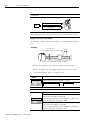
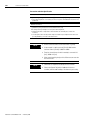
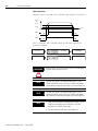
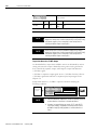
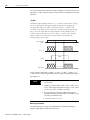
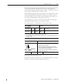
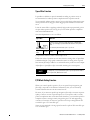
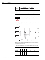
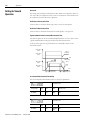
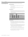
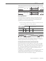
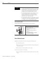
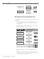
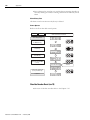
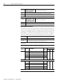
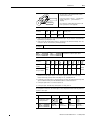
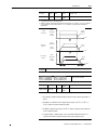
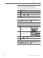
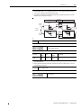
Sets the signal’s trigger condition at position error clear input to clear the error to ‘0’.
Set value
Details
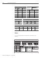
0
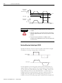
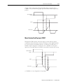
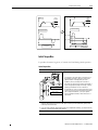
Cleared at H level.
As long as H level is maintained, the error stays at (0).
1
Cleared only once at rising edge.
2
Cleared at L level.
As long as L level is maintained, the error stays at (0).
3
Cleared only once at falling edge.
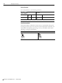
Applicable
modes
P
Detailed
description
Refer to Chapter 5-9
Other details
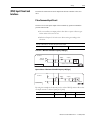
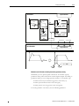
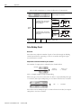
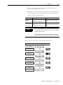
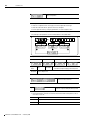
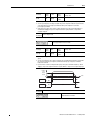
"H"
"L"
Servo-OFF>Setting>End
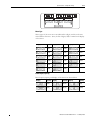
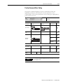
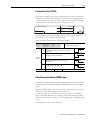
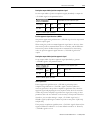
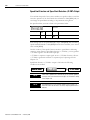
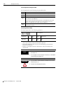
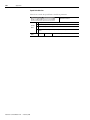
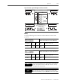
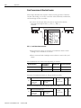
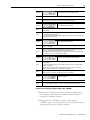
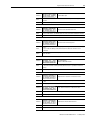
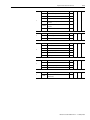
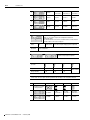
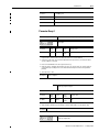
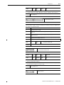
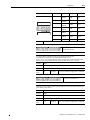
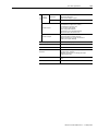
Electronic gear (Numerator)
Electronic gear (Denominator)
Set range
Initial
value
Unit
Other
details
Servo-OFF>Setting>End
1~65535
2048
[pulse]
Applicable
modes
P
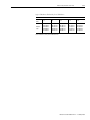
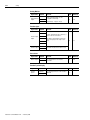
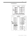
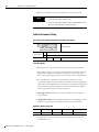
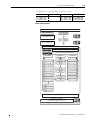
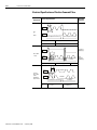
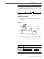
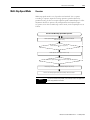
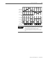
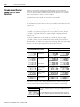
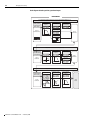
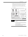
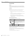
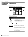
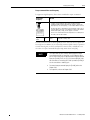
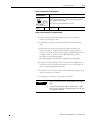
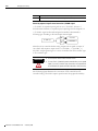
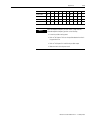
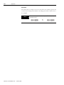
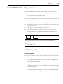
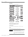
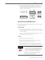
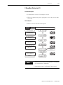
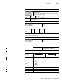
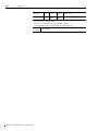
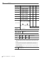
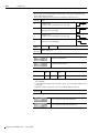
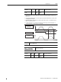
• By using the electronic gear function, the amount of motor rotation pr input command pulse can
be set arbitrarily.
• The following relationship has to be satisfied: No.,of pulses per 1 motor rotation x Reduction ratio
x 4 (Pr-3.02)
• Maximum resolution=1/ ([No.of pulses per 1 motor rotation] x [Reduction ratio] x 4)
Detailed
description
Refer to Chapter 5-9
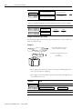
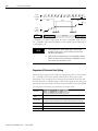
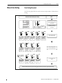
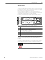
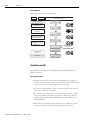
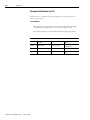
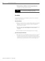
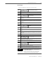
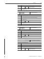
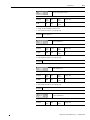
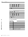
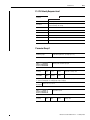
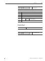
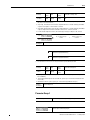
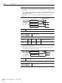
Position output pulse adjustment (Numerator)
Position output pulse adjustment (Denominator)
Publication CSD3P-UM001E-EN-P — February 2008