1
Wiring
3-17
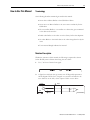
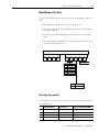
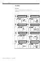
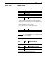
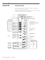
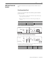
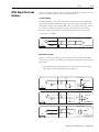
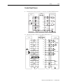
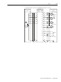
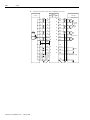
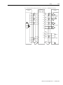
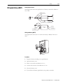
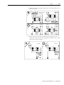
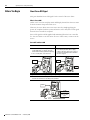
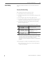
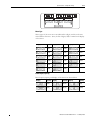
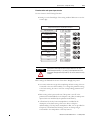
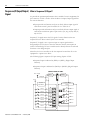
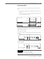
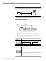
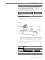
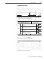
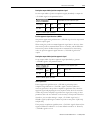
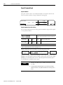
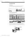
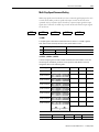
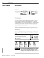
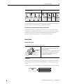
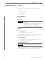
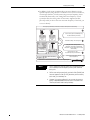
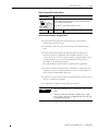
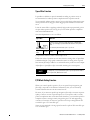
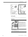
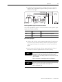
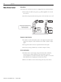
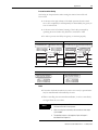
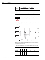
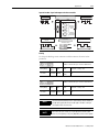
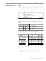
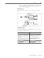
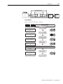
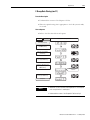
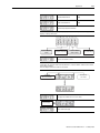
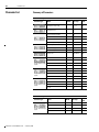
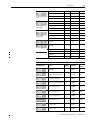
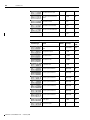
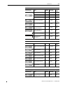
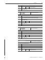
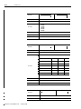
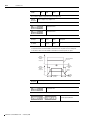
Sequence Input Circuit
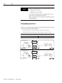
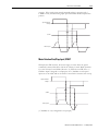
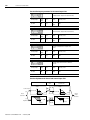
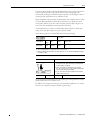
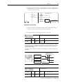
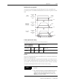
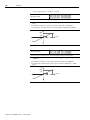
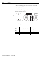
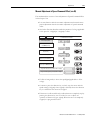
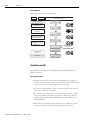
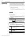
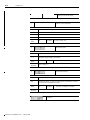
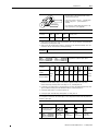
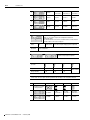
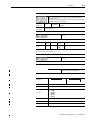
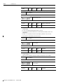
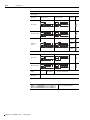
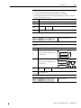
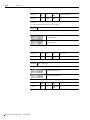
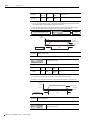
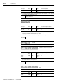
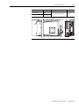
Relay or open collector output of the host controller is used for the sequence input
circuit.
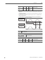
• Make sure that the input current i is within 7 [mA] to 15 [mA].
Relay Circuit
+24[V]IN
i
DC24[V] 50[mA]
or Higher
3.3[k˟]
P
CN1
Sequence Input Signal
(DI#1 to DI#7)
Host Controller
Open Colletor Circuit
i
DC24[V] 50[mA]
or Higher
3.3[k˟]
+24[V]IN
P
Sequence Input Signal
(DI#1 to DI#7)
Host Controller
CN1
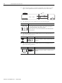
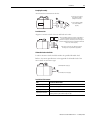
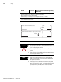
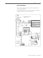
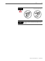
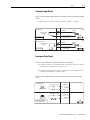
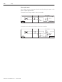
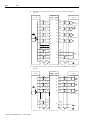
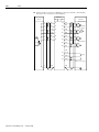
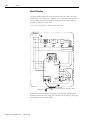
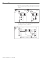
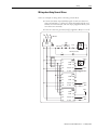
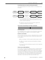
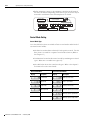
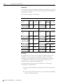
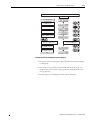
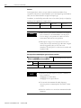
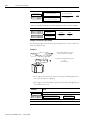
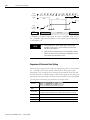
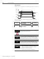
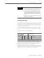
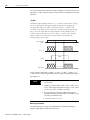
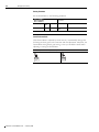
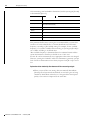
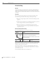
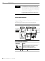
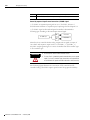
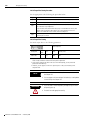
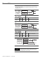
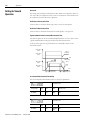
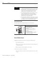
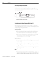
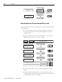
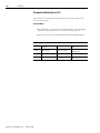
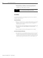
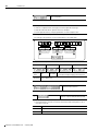
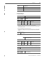
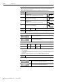
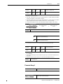
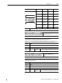
Emergency Stop Signal
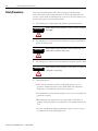
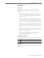
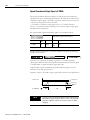
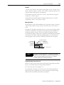
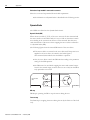
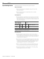
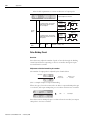
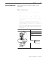
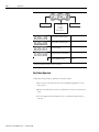
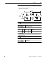
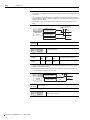
This drive has a built-in circuit for the emergency stop situation.
• To quickly respond to the equipment failure or dangerous situation, it receives
the emergency stop signal from #10 pin of CN1.
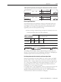
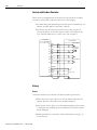
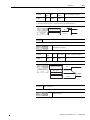
• Emergency stop input can be done by the relay contact output of host
controller and installing a separate switch.
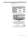
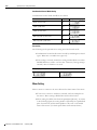
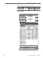
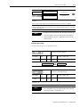
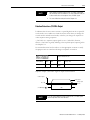
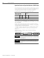
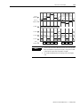
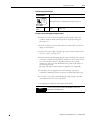
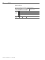
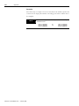
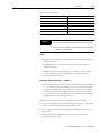
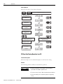
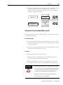
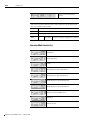
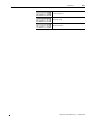
#10 pin of CN1 assigned below is used as the input pin only for the emergency
stop.
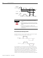
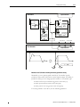
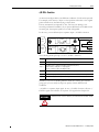
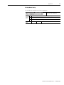
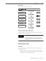
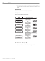
Normal Operation
External Power 24[V]
E-STOP
E-STOP Switch
E-Stop
External Power 24[V]
E-STOP Switch
Install a host controller
or a separate switch.
+24[V] IN
+24[V] IN
E-STOP
1/2
10
1/2
10
CN
1
Publication CSD3P-UM001E-EN-P — February 2008