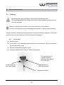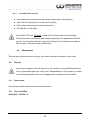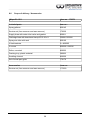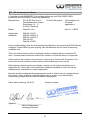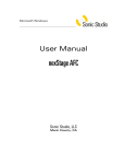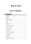
1
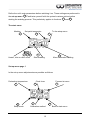
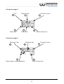
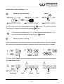
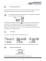
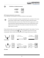
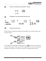
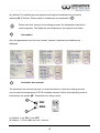
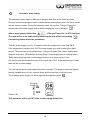
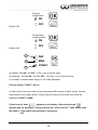
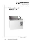
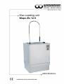
Wax scalding unit Wapo-Ex 12 II USER MANUAL Dear customer, Thank you for choosing a product from the Wassermann range. Wassermann DentalMaschinen incorporates the highest standards of quality and the latest technology. In order to enjoy maximum performance and years of trouble-free operation, please read this user manual carefully before you connect this device and start work, and operate the device according to the recommended guidelines. The operation safety and the functionality of this device can only be guaranteed if you follow both the general safety guidelines and the applying laws to prevent accidents as well as the precautions given in this user manual. We are not liable for any damages which occur due to inappropriate usage or faulty operation of this device. Make sure that anyone using this device has read and understood this user manual. Keep this user manual in a safe place where it can be referred to as required at any time. Company address: Wassermann Dental-Maschinen GmbH Rudorffweg 15-17 D-21031 Hamburg, Germany Phone. : +49 (0)40 / 730 926 – 0 Fax.: +49 (0)40 / 730 37 24 E-mail: [email protected] URL: http//www.wassermann-dental.com . Erstellt: 30.04.2015 / msc Version: 4 Wapo-Ex 12 II: 170970 ab # 154836 Contents 1 Features....................................................................................................................................... 4 2 Safety guidelines.......................................................................................................................... 5 2.1 Safety symbols used in this manual.......................................................................................5 2.2 Safety guidelines................................................................................................................... 5 2.3 Responsibility for operation or damage.................................................................................6 3 Application.................................................................................................................................... 6 4 Before starting.............................................................................................................................. 6 4.1 Transport............................................................................................................................... 6 4.2 Installation............................................................................................................................. 7 4.3 Storage.................................................................................................................................. 7 5 Installation / Start-up / Menu functions.........................................................................................8 5.1 Water supply.......................................................................................................................... 8 5.2 Fitting the spray gallows........................................................................................................8 5.3 Preparation............................................................................................................................ 9 5.4 Start-up................................................................................................................................ 10 6 Operation................................................................................................................................... 22 6.1 General operating instructions.............................................................................................22 6.2 Operation............................................................................................................................. 23 6.3 Manual spray head.............................................................................................................. 23 7 Troubleshooting.......................................................................................................................... 25 8 Care and maintenance............................................................................................................... 26 8.1 Cleaning.............................................................................................................................. 26 8.1.1 1x per week.................................................................................................................. 26 8.1.2 Every 6 weeks.............................................................................................................. 27 8.1.3 6-monthly lime removal.................................................................................................28 8.2 Maintenance........................................................................................................................ 28 8.3 Repairs................................................................................................................................ 28 8.4 Spare parts.......................................................................................................................... 28 8.5 Service hotline..................................................................................................................... 28 8.6 Scope of delivery / Accessories...........................................................................................29 8.7 Warranty.............................................................................................................................. 30 9 Technical data............................................................................................................................ 30 10 EC Conformity Certificate......................................................................................................... 31 1 Features The Wapo-Ex 12 II combines all-round skill, years of experience and the latest technology to produce an outstanding product. This well-designed free standing unit with integrated spray gallows scalds up to 12 flask halves simultaneously and fully automatically. The innovative multifunction touch-screen terminal offers diverse functions and reproducible procedures by simple programming. The Wapo-Ex 12 II is very durable and stands out thanks to its flexible usage, programmable timer and automatic wax removal. The electronic water level gauge, the leakage signal and the inlet limitation ensure additional safety. free standing unit for scalding up to 12 flask halves or 8 IVOCAP flask halves multifunction touch-screen terminal for easiest operation efficient usage thanks to its programmable timer and automatic wax removal stainless steel construction safety features with visual and audible signals easy to clean and easy to operate very durable and energy saving because of the intelligent heating control and the high quality insulation 4 2 2.1 Safety guidelines Safety symbols used in this manual Warning! This is a warning of risk situations and dangers. Failure to observe this warning could be life-threatening. These warnings has to be observed. Information! This symbol draws your attention to specific features that has to be observed. 2.2 Safety guidelines Configuring and operating this equipment requires precise knowledge and observance of the instructions in this user manual. The equipment is designed only for its intended application. WARNING: Servicing and repairs should be carried out only by authorised specialists. Disconnect the power plug before starting any maintenance work. Make sure that the equipment is connected to the correct power source. Risk of scalding! Do not hold the manual spray head by the rose or hose. Do not direct the spray at other people. Water coming from the spray head can be at temperatures up to 95°C; only direct the head towards the cover area or washbasin. 5 2.3 Responsibility for operation or damage The responsibility for operating the device lies exclusively with the owner or user if said device is incorrectly serviced, maintained or altered by persons not employed by an authorised dealer or if the device is used in a manner contrary to its specified purpose. The unit has to be maintained and operated in accordance with this user manual. Wassermann Dental-Maschinen GmbH is not responsible for damage arising from the nonobservance of these instructions. Warranty and responsibility provisions contained in the sales and supply conditions of Wassermann Dental-Maschinen GmbH are not extended by these instructions. 3 Application The Wapo-Ex 12 II is suitable for scalding wax for up to 12 flask halves and also for scalding smaller parts in the deeper cover by using the manual spray head. Only use the device for this type of application. 4 4.1 Before starting Transport Before transporting the unit, ensure that it has been unplugged from the power socket. Make sure that it is packed correctly in order to avoid accidental damage. Be sure to check for any transport damage when unpacking the goods. Note down any damage if found. 6 4.2 Installation Open the box, remove the packing materials, and carefully lift out the device and accessories. Check the included accessories. The device has to stand horizontally on a steady and even surface. Set the unit up close to a water supply tap with ¾” external thread and a water drain. Install the device in a place where it will not block the working area and the functionality (take the dimensions into account): Height with spray gallows: 1600 mm Width included side wall distance (right): 700 mm Depth included wall distance (rearwards): 670 mm Make sure the water drain level is above 470 mm Leave a side clearance of at least 50 mm at the right and the rear side of the unit to allow adequate heat circulation. Tip: Install the unit under an extractor hood to remove the steam. It has to be fitted with a fuse (16 A / 230 V). Do not install the unit outdoors or in places without proper ventilation. Before start-up, be sure the device reaches room temperature. 4.3 Storage If the unit is to be stored for an extended period, protect it from moisture and dust. 7 5 Installation / Start-up / Menu functions Before starting the unit, connect up the following: 5.1 Water supply Insert the supplied feeder hose gasket in its seat. Connect the hose to the tap. Connect the drain hose with the help of a hose clamp to the outlet on the unit. Make sure the hose it at a suitable height above the feeder pipe. The minimum amount of water should be about 4,5 l/min at a supply pressure of 1,5- max. 6 bar. 5.2 Fitting the spray gallows Raise the coil until the screw fitting can be seen. In order to avoid injury, be sure to take hold of the spacer to raise the coil. Angle the head over the spray area and screw in the gallows. 8 5.3 Preparation As well as connecting the unit correctly, the following tasks need to be carried out before you start-up: Remove both sliding covers; Remove the flasks, fence for smal parts and scalding channel; Swing the spray arm up and remove; Remove the large, loose stainless steel basket; Check that the pump filter is sitting correctly in place; Remove remaining packaging; Insert roller in bearing. The roller carrier can only be inserted vertically in the vertical holder for the drive shaft. Reinsert the large stainless steel basket; Fit fence for smal parts in the large stainless steel basket. Fit the spray arm on the connecting joint and swing it down (bayonet connector). Make sure all seals are clean. Insert the channel from the front so that any small particles can be caught in the mesh of the large stainless steel basket. Swing the handle in again when reinserting the flask holders. Fit sliding cover and close (turn through 180°). Remove cover (magnetic mount on front of unit) and close drain tap (lever horizontal). Insert the waste container under the drain tap. Replace cover. Open tap and check feeder hose for leaks. The unit can be emptied using a siphon; make sure the drain hose does not leak and is firmly attached to prevent it coming loose. If there is no waste drain, hang the hose in a washbasin. 9 5.4 Start-up Prior to initial operation, attach and check the feeder and drain hoses! Firmly clamp the supplied drainage hose to the device and ensure there is a suitable drainage facility. The selector lever The following functions can be set using the selector lever: 6 19 Automatic scalding Pump down 5 Manual spraying Pull up the selector lever to unlock. Insert the power plug into the socket, making sure that the mains and the unit operate on the same voltage. Turn on the main switch (green rocker switch). Set the selector lever to the "Automatic scalding" position Touch on . and water supply is activated or if already activated before (please see point 18 ) the machine fills up automatically. Please note the safety function, if necessary, pull the lever up to unlock. After switching on the unit After switching on the unit without automatic water supply with automatic water supply the display shows: the display shows: 10 Water fills the container to the working level and is heated to the operating temperature automatically (approximately 1.5 hours). The default setting for this is 85 °C/185 °F. Add wax remover once the operating temperature (nominal temperature display 85 °C) has been reached. Use the manual spray to do this. Add 100 ml wax remover (without solvent) to the scalding channel. Set the selector lever to Tap the A symbol on the display. The process must be ended manually. Stop the process by pressing the A symbol again. Set the selector lever back to position. Follow unlocking procedure. "Automatic scalding" again. A Wax remover only needs to be added as discribed above if the water is changed or water is lost (depends on work load). The following safety instructions have to be followed for safe work with the manual spray: Adjust the spray so that the spray holes are directed towards the channels. Do not hold the manual spray head by the rose or hose. Do not direct the spray at other people. We recommend the use of gloves because of the high temperatures (up to 95°C) involved. 11 Define the unit's main parameters before switching it on. These settings are performed in the set-up menu 3 . Familiarise yourself with the system's various options before starting the scalding process. This particularly applies to functions 7 and 14 . The start menu Marking 1 Set-point temperatur To the setup menu 2 4 17 18 Heater, inlet or roller on/off 3 5 6 Menu automatic scalding Start scalding Set-up menu page 1 In the set-up menu adjustments are possible as follows: Preheating temperature Clock timer 8 7 10 Sleep mode Forward at menu 9 11 16 Calibration method 12 Back to start menu Set-up menu page 2 °C/°F 12 Date and time 13 14 Forward at menu 9 15 Work mode 16 Information Back to start menu Set-up menu page 3 Parameter roller 17 Parameter inlet Forward at menu 9 18 20 16 Water supply in manual operation Back to start menu 13 Specification of the operation 5 – 19 5 Menu manual spray head Heater B A The manual spray process is started by pressing the A symbol. The symbol is inverted. The process is stopped by pressing the inverted A symbol. This function is available from 66 °C. If the temperature falls below 66 °C the process is cancelled and the heating symbol 6 B appears. Menu automatic scalding Define the parameters for scalding temperature and scalding duration. By briefly tapping the numbers, the parameter selected is expanded and the values can then be changed. Touch the arrow (Start) to start the program. Interrupt or cancel the program by pressing the "Stop/Pause"symbol. Stop/break Stop Break 14 Back Start 7 Preheating temperature Defines the target temperature once the main switch has been activated. The pre-heat temperature also applies to waiting times and rest periods. Default: 85 °C If the programme temperature selected is higher, the temperature reverts back to this value when the programme ends. After defining the desired working mode 14 , it may make sense to adjust the pre-heat temperature of the programme temperature. This avoids long heat-up or cool-down phases. The pre-heat temperature may be up to 8 °C higher than the programme temperature for the programme to start. The control system will then adjust (reduce) the temperature to the programmed value. 8 Clock timer This defines the weekday activation and deactivation times. Ongoing programmes have a higher priority; they are not switched off until complete. 10 Display of the sleep mode By touching the sleep symbol the unit changes into the sleep mode. 15 11 Definition of calibration method DEF: Default (calibrated for mains water) CAL Calibration (only necessary for extreme deviations in water quality) This ensures temperature sensors are adjusted to the conductance of the water. How it works: Pump out water. The water level drops to below the sensor. Evaluate temperature sensors values. Water fills until the upper sensor is well covered by water. Evaluate temperature sensors values. Should there not be sufficient time to fill with water, then please manually fill with water until the upper sensor is covered. Ensure that the water level is close to the upper sensor (page 24: Figure below). Turn the selector lever to the pump position 19 . The calibration process will now start automatically. Please confirm the calibration with OK (images below are just similar). Drain water Fill water 16 12 Selection of temperatur (Fahrenheit or Celsius) 13 Pictogram for the time and date function cycle. 14 Selection of work mode Defines whether the scalding time should start immediately or only after the heating value has been reached. a b (a) Unit heats up to the temperature programmed under 6 plus tolerance to compensate for heat loss through the conveying pump. After reaching this value, the result measured is validated by a control cycle. If the value is confirmed, the scalding process will start. 17 (b) (default) The scalding process programmed begins immediately but not before reaching 66 °C Celsius. Please select a suitable pre-set temperature 7 . Please note that, owing to the scalding process, the temperature can fall by several degrees. The higher the set temperature, the higher the deviation. 15 Information Here the parameters from the touch screen, sensors, hardware and software are displayed. 17 Automatic wax removal The automatic wax removal process is conducted before or after the scalding process once a minimum temperature of 75 °C has been reached. Active removal/rolling mode is indicated by the symbol . . Parameters for rolling control. a DEF MAN b (a) Default: 3 min ON / 3 min OFF. (b) Manuel: 1-29 min ON / time-off = time-on. 18 18 Automatic water supply The automatic water supply is different in program flow than in the stand-by mode. During a continuous program water is refilled always automatically when the lower sensor has no contact to water. During the stand-by mode the function „Filling at Power-On“ decides about the water supply with or without asking the user in advance. After a water supply disfunction „Filling at Power-On“ is OFF (inactive). The hold-up has to be unblocked by switching the unit off/on and pushing . If necessary please match the parameters. Than the water supply runs for 10 seconds when the temperatur is less than 78°C. If the temperature is higher than 78°C the water supply runs until reaching the upper sensor. There are two further parameters: „Filling at Program End“ (water supply when program ends) and „Filling before entering Sleep“ (water supply before entering sleep ). These parameters regulate if water supply should run to these points in time. For that function the temperature has to be higher than 78°C. If the temperature is lower there will be no water supply. The inlet can be done in adjustable intervals or constant. The programming can happen through variable times of inlet, intervall times and the total time of all inlet times. The activated water supply can be recognized through the symbol Filling at Power-On ON OFF Default: ON This parameter will be set OFF after a water supply disfunction. 19 .. Filling at Programend ON OFF Default: ON Filling before entering Sleep ON OFF Default: ON a b c DEF MAN CONST (a) Default: 30s ON / 90s OFF / 120s = sum of all ON times (b) Manually: 10s-59s ON / 0s-199s OFF / 10s-199s = sum of all ON times (c) Constant: constant water supply of 10s-199s adjustable Factory setting: CONST = 60 sec. In order to be on the save side we have programed 60 seconds of water supply from the lower sensor to the upper sensor. Please conform this time to the real time under the parameter CONST or MAN. If time is set to short appears on the display. After switching on appears and the parameter „Filling at Power-On“ will be set OFF. Than please push the button to match the parameter if necessary. 20 19 Pump down / drain Unlock the selector lever by pulling up and moving the selector lever to the pump out symbol. Now this symbol appears on the display. Tap to now start or interrupt the pumping process. End the process as soon as the container is empty. The next water supply has to be confirmed by tap the symbol . Operating the pump without water may cause the pump to fail. 20 Water supply in manual operation The mode of operation is simular to the automatic water supply 18 . 21 6 6.1 Operation General operating instructions All instructions for using the unit, whether in verbal or written form, are based on our own experience and experimentation and can only be regarded as guidelines. The Wapo-Ex 12 II is protected against running dry if the water is too low. A warning signal also sounds if the water level is too low. An additional safeguard protects the heater against overheating; it is automatically deactivated at temperatures above 97 °C. Use heat-resistant gloves when working with the Wapo-Ex 12 II. Remove the power plug if the unit is not to be used for a long period. Use a touchpen to prolong the life of the screen protector. 22 6.2 Operation Switch on the main switch (green rocker switch). The water supply takes place if the automatic water supply is activated. Othervise press to activeate the water supply . Place prepared cuvettes into the unit's clamp. Unlock the selector lever and set to automatic for automatic scalding. Automatic scalding (temperature/time) is started by the C or D symbol. After the scalding process has ended, the temperature falls/rises to the preset temperature 7 again. D 6.3 A C Manual spray head To manually scald using the spray, the selector lever must be set to the position. Follow unlocking procedure. Then, tap the A symbol on the display to start the process. The process must be ended by manually tapping the inverted A symbol. In its ready state (> 66 °C), the manual spray can be activated at any time by moving the selector lever. Please pay attention to the warning signs. 23 The Wapo Ex-12 (II) is only ready for operation at temperatures above 66 °C, i.e. the pump only starts working after the set temperature has been reached. An additional safeguard protects the heater from overheating; it is automatically deactivated at temperatures above 97 °C. Risk of scalding! Do not hold the manual spray head by the rose or hose. Do not direct the spray at other people. Water coming from the spray head can be at temperatures up to 95°C; only direct the head towards the cover area or washbasin. 24 7 Troubleshooting Fault Cause Wapo-Ex 12 II does not Combi sensor is dirty heat Symbol „lid open“ Sliding lid is open Remedy Clean the combi sensor Display of water deficiency Clean the combi sensor Combi sensor is dirty Close the sliding lid Water deficiency Ensure water supply. Time of inlet to short, change as described in point 18 . Check the parameter „Filling at Power On“. Display of leakage Overflow / leakage Immediately switch off the unit and check if there is a leakage! Just switch on the unit after the problem is located and solved. Time of inlet to short, change as described in point 18 . Check the parameter „Filling at Power On“. Touch display does not Calibrate the touch display Switch on the unit. While the logo of work correctly Wassermann appears please contact the touch display two times. Then you will reach the selfexplanatory touch panel-calibration (Fig. 1-2). Screen protector Please contact our service damaged? (see 8.5) Programm does not start In work mode (a) wilfully This is not an error. Please wait although the set the temperature is 1° approx. 3 minutes. temperature is reached. overheated and the program waits one minute to validate the values. Figure 1 Figure 2 If the above recommendations do not solve the problem, contact your dental depot or our service department. 25 8 Care and maintenance 8.1 Cleaning Disconnect the power plug before starting any maintenance work. The identification plate has always to be kept in easily legible condition and has not to be removed. Remove external dirt from time to time with some form of cold cleaner. Use only cold cleaners to avoid damaging the paintwork or removing the lettering. The unit should be cleaned at regular intervals to ensure trouble-free operation. Clean the outside of the unit with a sponge or soft cloth and mild detergent. 8.1.1 1x per week Remove cover. If more than ¾ full, the waste wax container has to be emptied. This can be reused for less high-quality work. Reinsert container and replace cover.. Clean the combi-sensor (every 2 nd week at the latest) The combi-sensor is located below the cleaning roller (slightly off to the right). Lower sensor (L) Min. filling height Upper sensor (U) Max. filling height Temperature sensor 26 8.1.2 Every 6 weeks The water may need changing earlier or later, depending on use and water hardness. We recommend every 6 weeks. Wax removal should be carried out before changing the water to keep the amount of wax in the drain hose as low as possible. This can occur early in the day, 30 minutes before the unit switches off automatically. The water temperature should be 85°C. Follow the steps below when changing the water: Unit has to be heated to a water temperature of 75°C. Turn off tap and check drain hose is connected correctly to siphon or is hanging in wash basin. Set function switch to "Pump down". Switch on the pump by touching the symbol After pump-down (siphoned air will cause a gurgling noise), the pump has to be . switched off by touching the display symbol a second time. Reset function switch to "Automatic scalding" position. Switch unit off completely (main switch on). The remaining water can now be removed with the wax drain container (lever vertical). Process has to be repeated several times as the container cannot hold all the remaining water. Important: Return drain lever to the horizontal after removing the remaining water. Before refilling the unit the interior and the pump filter have to be cleaned. The combi sensor (right side next to pump inlet) should also be cleaned. Check for lime on the heater. Cleaning the roller brushes is neither necessary nor advisable. 27 8.1.3 6-monthly lime removal Intermediate lime removal may be needed, depending on the build-up. Up to 500 ccm depending on instrument condition Drain water containing too much wax dissolver Mix Kalk-Ex in cold water Allow KALK–EX max. 12 hours to work. Drain solution and rinse thoroughly. Observe protective measures (wear wraparound protective glasses and suitable gloves). Avoid contact with skin, eyes and clothing. Do not swallow or breathe in lime remover. Otherwise seek medical help. 8.2 Maintenance The unit does not require any servicing. Just make sure that the device is kept clean. 8.3 Repairs Servicing or repairs to the unit has only to be carried out by qualified technicians. Only original spare parts are to be used. Responsibility for the product is voided if unauthorised persons alter it or if inappropriate components are installed. 8.4 Spare parts If necessary please contact our service hotline phone. 8.5 Service hotline 0049 (0)40 / 730 926 - 0 28 8.6 Scope of delivery / Accessories Wapo-Ex 12 II Item no.: 170970 Included parts Item no.: Spray gallows 830145 Service set (lime remover and wax remover) 170330 Supply hose with water inlet valve and gasket 830011 Discharge hose with hose band clamp Ø 12-20 x 9 320061/322006 Spray arm tube with seal 830160 2 flask baskets 2 x 830205 2 covers 830230 / 830235 Roller, mounted 830223 Draining tray, plastic material 390033 Scalding channel 830220 Set of small part grids 170179 Accessories Item no.: Service set (lime remover and wax remover) 170330 29 8.7 Warranty The warranty period for our equipment is 12 months. If faults occur within the warranty period, contact your dental depot or get in touch directly with our service department. Your equipment should only be operated in perfect condition. If faults occur which could harm operators or third parties, the unit should not be used until it has been fixed. This warranty does not cover damage caused by improper use, external mechanical causes, transport damage or interference with the unit by unauthorized persons. 9 Technical data Wapo-Ex 12 II Voltage* Power consumption Output W x H (without spray gallows) x D W x H (with spray gallows) x D Weight Sound level Water capacity Water feed rate Water drain height Item No.: 170970 220–240 V / 50/60 Hz 12 A max. 3300 W 650 x 900 x 620 mm 650 x 1600 x 620 mm 87 kg ≤ 70 dB (A) approx. 50 l 4,5 l / min 470 mm *Other voltages on request. The noise level of the unit amounts to ≤ 70 dB (A). Technical changes reserved. 30 10 EC Conformity Certificate in accordance with 2006/95/EG (low-voltage guidelines) and 2004/108/EG (EMV guidelines) and 2006/42/EG (machinery guidelines) Manufacturer: WASSERMANN Dental-Maschinen GmbH Rudorffweg 15 - 17 D-21031 Hamburg Model: Wapo-Ex-12 II Aapplicable standards: DIN EN 61010-1 DIN EN 61000-6-3 DIN EN 61000-6-1 DIN 45635-1 DIN EN 60335-1 Product description: Wax scalding unit for dental applications Item no. 170970 Hiermit wird bestätigt, dass die oben bezeichnete Maschine den genannten EG-Richtlinien entspricht. Diese Erklärung wird ungültig, falls die Maschine ohne unsere Zustimmung verändert wird. This is to confirm that the above mentioned machine complies with the described EC rules. This declaration becomes invalid if the machine is modified without our approval. Cette machine est conforme aux normes en vigueur de la Communité Européene. Cet avis est nul et non avenant si cette machine est modifiée sans notre accord. Esta máquina, anteriormente mencionada, cumple con los limites requeridos por el reglamento EC. Ahora bien, esta declaración quedará invalidada en caso de realizar modificaciones al aparato sin nuestra aprobación. Hiermee wordt bevestigd dat bovengenoemde machine voldoet aan de voorgeschreven EU normen. Deze verklaring verliest geldigheid als er zonder onze uitdrukkelijke toestemming wijzigen aan de machine worden aangebracht. Place, date: Hamburg, 30.04.15 Company stamp: Signature : ________________________ Wilfried Wassermann (Managing Director) 31