1
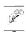
Mounting/Removing the Positioning CPU and Connecting Cables
2.7
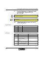
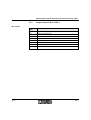
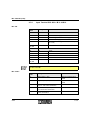
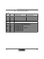
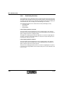
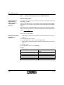
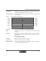
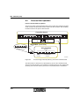
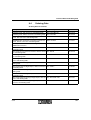
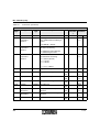
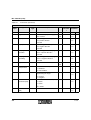
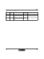
Terminal Assignment for Input and Output
Terminals When Operated With the
IB IL POS 200
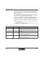
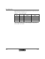
The order numbers for the various input and output terminals can be found in the
"Ordering Data" on page 9-11.
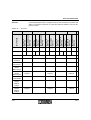
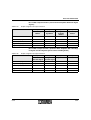
The functions of the individual output versions are described in section 6, "Basic
Parameterization".
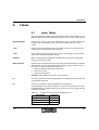
2.7.1
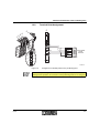
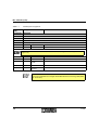
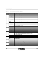
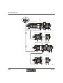
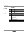
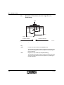
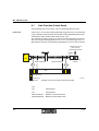
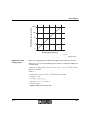
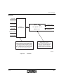
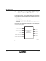
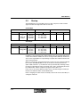
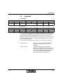
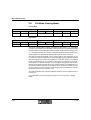
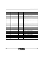
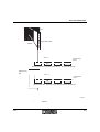
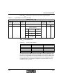
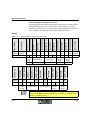
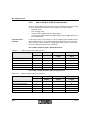
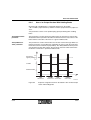
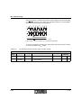
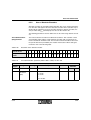
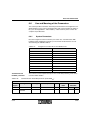
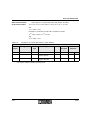
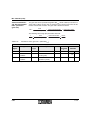
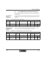
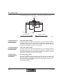
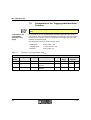
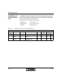
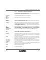
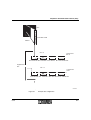
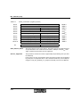
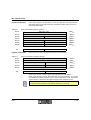
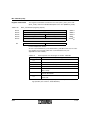
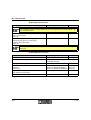
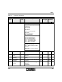
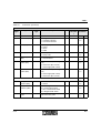
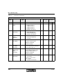
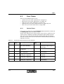
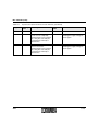
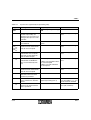
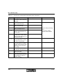
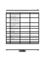
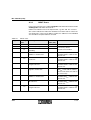
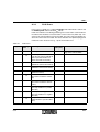
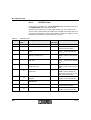
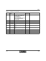
Output Terminal IB IL AO 2/U/BP + IB IL 24 DO 2
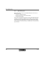
Without Holding Brake
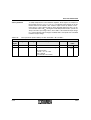
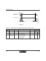
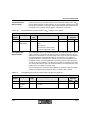
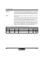
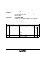
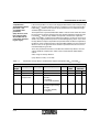
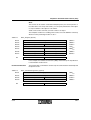
IB IL AO 2/U/BP
Terminal
Point
Signal
Assignment
1.1
U1
Voltage output 1 (0 V to +10 V analog)
2.1
U2
Voltage output 2 (not used)
1.2, 2.2
–
Not used
1.3, 2.3
AGND
Voltage output ground
1.4, 2.4
Shield
Shield connection
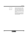
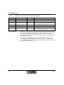
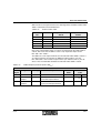
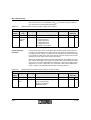
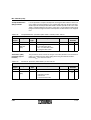
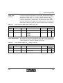
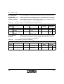
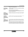
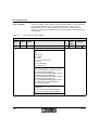
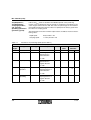
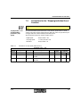
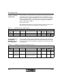
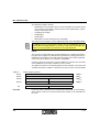
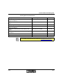
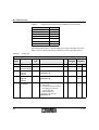
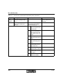
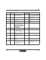
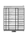
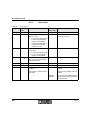
Terminal
Point
Assignment
1.1
Signal output (OUT1)
Enable positive motion
2.1
Signal output (OUT2)
Enable negative motion
1.2, 2.2
Segment voltage US
for 4-wire termination
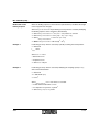
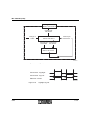
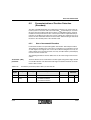
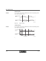
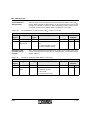
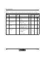
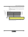
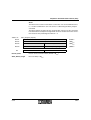
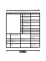
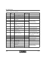
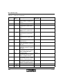
IB IL 24 DO 2
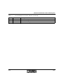
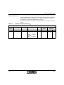
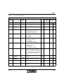
Remark
Measuring point for the supply
voltage
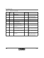
657601
1.3, 2.3
Ground contact (GND)
for 2, 3, and 4-wire termination
1.4, 2.4
FE connection
for 2 and 3-wire termination
2-11