1
SilverMax
User Manual
Revision 3.22 – September 2001
SilverMax, QuickControl and PVIA are trademarks of QuickSilver Controls, Inc.
The SilverMax embedded software, SilverMax electronic circuit board designs, and the embedded
logic in the contained CPLDs, as well as this SilverMax User Manual are Copyright © 1996-2001 by
QuickSilver Controls, Inc.
SilverMax User Manual
1
Revision 3.22
TABLE OF CONTENTS
INTRODUCTION........................................................................................................................................... 8
Warnings ...................................................................................................................................................... 8
What is contained in this User Manual ..................................................................................................... 9
GETTING STARTED .................................................................................................................................. 10
Start-Up Kits Overview ............................................................................................................................. 11
Start-Up Kit Hardware Setup ................................................................................................................... 12
QCI-SK1-FS-1 Start-Up Kit Setup ........................................................................................................... 12
QCI-SK1-34-1 Start-Up Kit Setup............................................................................................................ 13
QCI-SKO-FS-v Start-Up Kit Setup .......................................................................................................... 14
QCI-SKO-34-v Start-Up Kit Setup ........................................................................................................... 15
QCI-SKO-34-65-v Start-Up Kit Setup...................................................................................................... 16
Installing QuickControl Software ............................................................................................................ 17
SilverMax “Status” and “Comm” LEDs .................................................................................................. 18
UPGRADING FROM QUICKCONTROL 3.1 TO 3.2.................................................................................. 19
What is New?............................................................................................................................................. 19
SilverMax Initialization Wizard................................................................................................................. 19
Where Do I Set Motor Voltage?........................................................................................................... 19
How Do I Edit the Initialization Parameters? ....................................................................................... 19
Can I Still Use My Old Initialization Files? ........................................................................................... 19
Default Start Address........................................................................................................................... 19
SilverMax Control Panel .......................................................................................................................... 20
Single Step/Trace/Breakpoint.................................................................................................................. 20
QuickControl Rev 3.1 Tools .................................................................................................................... 21
SILVERMAX INITIALIZATION ................................................................................................................... 22
SilverMax Factory Default Initialization.qcp........................................................................................... 22
SilverMax Initialization Wizard................................................................................................................. 22
SilverMax Factory Default Initialization File - Detailed.......................................................................... 24
Main Init[0] ............................................................................................................................................... 25
Communications .................................................................................................................................. 25
Startup Error Conditions ...................................................................................................................... 26
Motor .................................................................................................................................................... 27
Servo Tuning........................................................................................................................................ 27
Motion .................................................................................................................................................. 28
Motor/Encoder Alignment Routine....................................................................................................... 28
Misc...................................................................................................................................................... 30
OVERVIEW ................................................................................................................................................. 31
SilverMax User Manual
2
Revision 3.22
SilverMax Block Diagram ......................................................................................................................... 31
Serial Communications ............................................................................................................................ 32
Communication Hardware....................................................................................................................... 32
RS-485 Multi-Drop ............................................................................................................................... 32
RS-232................................................................................................................................................. 32
RS-232 Multi-Drop ............................................................................................................................... 32
Communication Protocols ....................................................................................................................... 32
Command Processor ................................................................................................................................ 32
Digital I/O.................................................................................................................................................... 33
Analog Inputs ............................................................................................................................................ 33
Non-Volatile Memory ................................................................................................................................ 33
Trajectory Generator................................................................................................................................. 33
Servo Control Loop................................................................................................................................... 33
Motor Driver/Commutation ...................................................................................................................... 34
Brushless Motor........................................................................................................................................ 34
Position Feedback .................................................................................................................................... 34
SILVERMAX MOTION COMMANDS ......................................................................................................... 35
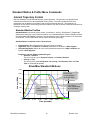
Standard Motion & Profile Move Commands ......................................................................................... 36
Internal Trajectory Control ....................................................................................................................... 36
Standard Motion Profiles ......................................................................................................................... 36
Standard Motion commands come in three flavors: ...................................................................... 36
“Relative” Move Commands.................................................................................................................... 37
Move Relative, Velocity Based (MRV) ........................................................................................... 37
Register Move Relative, Velocity Based (RRV)............................................................................. 37
Extended Register Move, Velocity Based (XRV)........................................................................... 37
Move Relative, Time Based (MRT)................................................................................................ 37
Register Move Relative, Time Based (RRT).................................................................................. 37
Extended Register Move Relative, Time Based (XRT) ................................................................. 37
“Absolute” Move Commands................................................................................................................... 38
Move Absolute, Velocity Based (MAV) .......................................................................................... 38
Register Move Absolute, Velocity Based (RAV) ............................................................................ 38
Extended Register Move Absolute, Velocity Based (XAV)............................................................ 38
Move Absolute, Time Based (MAT) ............................................................................................... 38
Register Move Absolute, Time Based (RAT)................................................................................. 38
Extended Register Move Absolute, Time Based (XAT)................................................................. 38
Moves Using Data Registers................................................................................................................... 39
Profile Moves........................................................................................................................................... 40
Velocity Mode Control ............................................................................................................................. 41
Torque Control (Using Velocity Mode) ................................................................................................ 41
External Trajectory Control...................................................................................................................... 42
SilverMax User Manual
3
Revision 3.22
Scaled Step and Direction (Electronic Gearing) ..................................................................................... 42
Position Input Mode................................................................................................................................. 42
Velocity and Torque Input Modes............................................................................................................ 42
USING INPUTS TO STOP MOTIONS........................................................................................................ 43
Standard Usage – Native SilverMax ........................................................................................................ 43
Standard Usage – QuickControl.............................................................................................................. 44
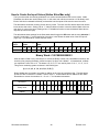
Advanced Usage – Native SilverMax ...................................................................................................... 45
Input Checking Process for Motion Commands...................................................................................... 45
First Check (Used to toggle the starting direction of motor) ................................................................ 45
Second Check (Used to do a Two-State input check)......................................................................... 45
Last Check (This may now stop the motor) ......................................................................................... 45
Stopping a Motion on Input.................................................................................................................. 46
Recording Sensor Found Position....................................................................................................... 46
Motion Profile Input Options Table .......................................................................................................... 48
Direction Toggle Conditions........................................................................................................... 48
How to Create the Input Values (Native SilverMax only) ........................................................................ 49
AND Inputs State ........................................................................................................................... 49
OR Inputs State.............................................................................................................................. 49
Using Inputs Examples............................................................................................................................. 51
Basic Stop on Input ................................................................................................................................. 51
AND Inputs State ........................................................................................................................... 51
OR Inputs State.............................................................................................................................. 51
Change Direction and Stop on Input ....................................................................................................... 52
AND Inputs State ........................................................................................................................... 52
OR Inputs State.............................................................................................................................. 52
Advanced Usage – QuickControl ............................................................................................................ 53
USING THE DIGITAL I/O ........................................................................................................................... 54
SilverMax E Series I/O Configuration Table............................................................................................ 54
Input & Output Functions......................................................................................................................... 55
Inputs ....................................................................................................................................................... 55
Outputs .................................................................................................................................................... 55
Basic Digital Inputs & Outputs ................................................................................................................ 56
Step & Direction Input (Encoder Input) .................................................................................................. 57
Step & Direction Output (Modulo Output) .............................................................................................. 58
Step & Direction ................................................................................................................................... 58
A & B Quatrature.................................................................................................................................. 59
Special I/O .................................................................................................................................................. 59
Encoder Output ....................................................................................................................................... 59
Done Status............................................................................................................................................. 59
USING ANALOG INPUTS.......................................................................................................................... 60
SilverMax User Manual
4
Revision 3.22
Selecting Analog Inputs ........................................................................................................................... 60
Single Channel Inputs ............................................................................................................................. 60
Differential Channel Inputs ...................................................................................................................... 61
Reading Analog Inputs ............................................................................................................................. 61
Reading and Calibrating the V+ Analog Input......................................................................................... 62
Reading and Calibrating the Temperature Analog Input......................................................................... 62
I/O CONFLICTS.......................................................................................................................................... 63
OPERATING IN HOST AND STANDALONE MODE ................................................................................ 64
Host Mode.................................................................................................................................................. 64
Polling SilverMax Using the Poll Command............................................................................................ 64
Standalone Mode ...................................................................................................................................... 66
Host & Standalone Mode Combined ....................................................................................................... 66
PROGRAMMING SILVERMAX.................................................................................................................. 67
SilverMax Memory Model ......................................................................................................................... 67
Serial Communications Buffer................................................................................................................. 67
Program Buffer ........................................................................................................................................ 67
Non-Volatile Memory ............................................................................................................................... 68
Creating Programs Overview................................................................................................................... 69
Command Types Required ..................................................................................................................... 69
How Programs Operate........................................................................................................................... 69
Motion Commands............................................................................................................................... 69
Wait Commands .................................................................................................................................. 69
Mode Commands................................................................................................................................. 69
Data Register Commands ................................................................................................................... 70
All other commands ............................................................................................................................. 70
Program Flow Control ............................................................................................................................. 70
Conditional Program Flow ....................................................................................................................... 70
If … Then … Else................................................................................................................................. 70
For … Next........................................................................................................................................... 71
While … Loop ...................................................................................................................................... 71
Do … While.......................................................................................................................................... 71
Using Digital I/O for Flow Control ........................................................................................................ 72
Downloading Programs Without QuickControl ..................................................................................... 73
Download Process .................................................................................................................................. 73
Program Download Example................................................................................................................... 74
Temporary Vs. Long Term Storage......................................................................................................... 74
Temporary Storage in Program Buffer ................................................................................................ 74
Long Term Storage in Non-Volatile Memory ....................................................................................... 75
SPECIAL MODES & OPERATIONS.......................................................................................................... 76
Anti-Hunt Operation (Eliminates Dithering) ........................................................................................... 76
Anti-Hunt Torque Settings ....................................................................................................................... 76
SilverMax User Manual
5
Revision 3.22
Anti-Hunt Delays...................................................................................................................................... 77
Anti-Hunt Examples................................................................................................................................. 77
Anti-Hunt Process.................................................................................................................................... 79
“Drag” Mode (Like a Mechanical Clutch) ............................................................................................... 80
Motor Shutdown (Kill Motor Conditions)................................................................................................ 81
Uncontrolled Shutdown ........................................................................................................................... 81
Controlled Shutdown ............................................................................................................................... 82
Kill Motor Conditions................................................................................................................................ 83
Kill Motor Condition Edit screen from QuickControl ...................................................................... 83
Kill Motor Recovery Program (Uncontrolled Shutdown) ......................................................................... 85
Kill Motor Recovery Program (Controlled Shutdown) ............................................................................. 86
Multi-Tasking Operation ........................................................................................................................... 87
The Primary Benefit of Multi-Tasking ...................................................................................................... 87
Other Benefits Include ............................................................................................................................. 87
Intelligent Motor Shutdown ............................................................................................................ 87
Analog Input Modes (Velocity, Position and Torque) ........................................................................... 90
Analog Input Resolution .......................................................................................................................... 90
Analog Read Methods............................................................................................................................. 90
Connecting Analog Inputs ....................................................................................................................... 90
Analog Input Mode Example Using a Potentiometer: ............................................................................. 91
Input Mode Description ........................................................................................................................... 93
Input Mode Data Processing Diagram .................................................................................................... 94
Calculations............................................................................................................................................... 95
Math Operations ...................................................................................................................................... 95
Bitwise Operations................................................................................................................................... 95
Data Register Operations........................................................................................................................ 96
Setting Motor Position ............................................................................................................................. 96
TUNING SILVERMAX ................................................................................................................................ 97
Control System Overview ........................................................................................................................ 97
SilverMax PVIA™ Servo Algorithm ......................................................................................................... 97
SilverMax Tuning Commands.................................................................................................................. 99
Primary Commands................................................................................................................................. 99
Associated Commands ........................................................................................................................... 99
Overview of the Control System Parameters....................................................................................... 100
Tuning Example – 100x1 Inertial Miss-Match....................................................................................... 109
Tuning Notes ........................................................................................................................................... 112
SILVERMAX 8-BIT AND 9-BIT COMMUNICATIONS PROTOCOLS ..................................................... 114
Choosing Which Protocol to Use .......................................................................................................... 114
Key Features of 8-bit ASCII................................................................................................................... 114
Key Features of 9-Bit Binary ................................................................................................................. 114
SilverMax User Manual
6
Revision 3.22
8-BIT ASCII COMMUNICATIONS............................................................................................................ 115
Command Packets .................................................................................................................................. 115
Start Character ...................................................................................................................................... 115
Address ................................................................................................................................................. 115
Command Code .................................................................................................................................... 116
Parameters ............................................................................................................................................ 116
Ending Character................................................................................................................................... 116
Examples ................................................................................................................................................. 116
Poll Command Packet ............................................................................................................................ 117
Response Packets .................................................................................................................................. 117
Acknowledge (ACK) Response ............................................................................................................. 117
Returned Data Response...................................................................................................................... 117
NAK Response ...................................................................................................................................... 118
9-BIT BINARY COMMUNICATIONS ....................................................................................................... 119
Command Packets .................................................................................................................................. 119
Address ................................................................................................................................................. 119
Length.................................................................................................................................................... 119
Command Code .................................................................................................................................... 120
Parameters ............................................................................................................................................ 120
Checksum.............................................................................................................................................. 120
Examples ................................................................................................................................................. 120
Poll Command Packet ............................................................................................................................ 121
Response Packets .................................................................................................................................. 122
ACK Response ...................................................................................................................................... 122
Returned Data Response...................................................................................................................... 123
NAK Response ...................................................................................................................................... 124
PROTOCOL DEFINITIONS...................................................................................................................... 125
SilverMax Negative Acknowledge (NAK) Codes ................................................................................. 125
SilverMax Polling Status Codes (Polling Status Word) ...................................................................... 126
SPECIFICATIONS .................................................................................................................................... 127
Digital I/O ..................................................................................................................................... 127
Analog Inputs ............................................................................................................................... 127
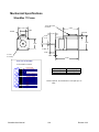
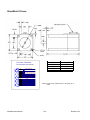
Mechanical Specifications ..................................................................................................................... 129
SilverMax 17 Frame .............................................................................................................................. 129
SilverMax 23 Frame .............................................................................................................................. 130
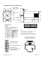
SilverMax 34N-1, 34H-1 & 34H-2 Frame .............................................................................................. 131
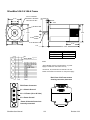
SilverMax 34H-3 & 34H-4 Frame .......................................................................................................... 132
INDEX ....................................................................................................................................................... 133
SilverMax User Manual
7
Revision 3.22
INTRODUCTION
SilverMax from QuickSilver Controls, Inc. is a fully integrated motion control system with the motion
trajectory controller, motor driver electronics, position encoder and motor all contained in one unit. It
requires less space than conventional controllers and simplifies the integration of your system. The
incorporated design requires just power and communications to be up and running. The work of
integrating a full vector controlled servo system has already been done for you. Smooth, quiet operation
with high performance motion control is ready to go.
SilverMax connects to a standard PC using RS-232 or RS-485 and an 8-Bit ASCII or 9-bit Binary
protocol. It is designed for master-slave communications and can be connected with other devices such
as sensors and data collectors from a single communications port.
SilverMax provides closed-loop servo control using 32-bit calculations. High-resolution position control
delivers precise executions every time. It produces smooth motion profiles with minimal noise and
vibration. SilverMax can store blocks of motion profiles for execution with a single command.
The available QuickControl software package makes rapid application development easy. And it contains
a fully featured command set that provides SilverMax set-up and complex motion control.
Optional C++ and Basic communications examples are available for integration into your source code.
Warnings
SilverMax shall not be used for Life Support applications without explicit written permission from
QuickSilver Controls, Inc.
SilverMax is a high performance motion system. As with any motion system, it is capable of
producing sufficient mechanical output to cause bodily injury and/or equipment damage if it is
improperly operated or if it malfunctions. The user shall not attach SilverMax to any mechanism
until its operation is fully understood. Furthermore, the user shall provide sufficient safety means
and measures to protect any operator from misuse or malfunction of the motion system. The user
assumes all liability for its use.
SilverMax User Manual
8
Revision 3.22
What is contained in this User Manual
This SilverMax User Manual is a reference manual design to aid the user in the operation and
programming of the SilverMax Servomotor family. A companion publication the “SilverMax Command
Reference” has the detailed description of the SilverMax command set. Many times this manual will
discuss or reference the commands detailed in the Command Reference. For this reason both
publications are needed for a full understanding of SilverMax operation and programming.
The User Manual is laid out to take the user through a natural progression of product usage.
Getting Started is where to begin since using a “Startup Kit” is probably the user’s first experience with
trying to setup and operate a SilverMax motor.
SilverMax Initialization is next and goes though the Initialization and Initialization programs used to
setup SilverMax for a specific application.
SilverMax Overview gives the user some basic knowledge of what is inside of SilverMax from a features
point of view.
SilverMax Motion Commands typically are at the top of the list of things to know about, so they are
covered right away.
From there, the manual goes through a number of important topics that give the basics of SilverMax
operation and programming.
This manual is not exhaustive. It would bore the user and waste everyone’s time. Detailed information for
specific applications can be found in QuickSilver Controls’ application example files found in the
QuickControl directory under “QCI Examples” and on QuickSilver Controls’ website at
www.QuickSilverControls.com or www.qcontrol.com where Application notes are updated periodically.
SilverMax User Manual
9
Revision 3.22
GETTING STARTED
BEFORE USING A SilverMax Motor:
•
•
•
Turn Off ALL Power Supplies and Switches
Read All Set-Up Instructions for Your Specific Motor or Start-Up Kit
Double-check ALL Intended Connections for Shorts or Unwanted Grounding
These setup instructions are designed to help you configure your SilverMax motor and QuickControl
Software. If you carefully follow the setup procedure for your specific SilverMax Start-Up Kit, your motor
should be operating within minutes.
Equipment required:
•
•
•
Personal computer with a 586 (at least 133 MHz) or higher processor running Windows 9x, NT
(4.0+), 2000 or Me.
SilverMax Motor
Startup Kit (SK1 or SKO) which includes:
• CD with QuickControl Software version 3.2 and higher
• SilverMax User Manual (this document)
• SilverMax Command Reference
• Cabling
NOTE: The following setup procedures require the usage of a SilverMax Start-Up Kit in order to
perform the setup and initialization. If you did not have a Startup Kit, contact your
distributor or QuickSilver Controls.
SilverMax Factory Defaults:
When shipped from the factory the SilverMax motor and Quicksilver software are configured with default
values that are used to establish initial communications between the motor and your computer. These
default values can be changed, “re-initialized”, to different settings during the Setup procedure if desired.
SilverMax Unit ID
SilverMax Supply Voltage
Serial Communications Protocol
Serial Interface
SilverMax User Manual
16
48VDC
8 bit ASCII
RS-232
10
Revision 3.22
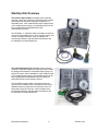
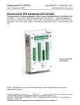
Start-Up Kits Overview
The QCI-SK1 Start-Up Kits (SilverMax motor, personal
computer, and power supply not included) provide a simple
and inexpensive means for testing and evaluation of a
SilverMax motor. With a standard PC serial COM port and
a user supplied power supply, any SilverMax motor can be
fully programmed and operated with RS-232
communication protocol.
The SilverMax “Y” evaluation cable is included in each kit to
connect your SilverMax motor to a PC, a power supply, and
a 9-Pin I/O breakout module. Also included are the
QuickControl Software, the SilverMax User Manual, and
the SilverMax Command Reference.
The QCI-SKO Start-Up Kits (SilverMax motor, personal
computer, and power supply not included) provide a means
for testing and evaluation of a SilverMax motor through an
Optical I/O board. With a standard PC serial COM port and
a user supplied power supply, any SilverMax motor can be
fully programmed and operated through an Optical I/O
board with RS-232 communication protocol.
The SilverMax Interface cable is included in each kit to
connect your SilverMax motor to the Optical I/O board. An
additional cable is provided for the connection of the I/O
board and a personal computer. Also included are the
QuickControl Software, the SilverMax User Manual, and
the SilverMax Command Reference.
SilverMax User Manual
11
Revision 3.22
Start-Up Kit Hardware Setup
NOTE: Set-up differs slightly between kits, so read entire set-up section of manual before connecting
anything to your motor)
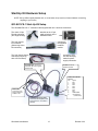
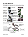
QCI-SK1-FS-1 Start-Up Kit Setup
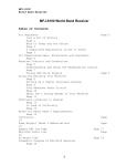
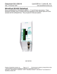
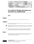
The SilverMax RS-232 “Y” evaluation cable supplied with Kit 1 has three connectors.
The center 15-pin
Female connector
(D15 High Density)
attaches to the 15-pin
male connector on the
SilverMax motor.
The 9-pin female
I/O connector
(Shorter leg with a
D9 connector)
connects to
the supplied
breakout
module.
The 9-pin female Comm
connector (longer leg
with a D9 connector)
connects to your
PC and has flying
leads for power
supply connection.
SilverMax D15: Connect to
SilverMax. Be sure to tighten
thumbscrews
I/O D9: Connect to
breakout module
I/O Breakout Module
Pin-out:
Pin:
Signal
1
I/O 1
2
I/O 2
3
I/O 3
4
I/O 4
5
I/O 5
6
I/O 6
7
I/O 7
8
LOGIC GND
9
+5V OUTPUT
(100ma max)
RS-232 D9:
Connect to 9-Pin
RS-232 COM1 or
COM2 on PC
Power Supply Flying leads:
Connect to user supplied power
supply (Red to V+ and black to
Ground)
SilverMax User Manual
12
Revision 3.22
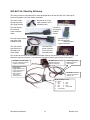
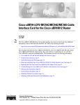
QCI-SK1-34-1 Start-Up Kit Setup
The Setup for this kit is the same as the setup described above for the QCI-SK1-FS-1 Start-Up Kit,
except a SilverMax Line Power Cable is Included.
The center 15-pin
Female connector
(D15 High Density)
attaches to the 15-pin
male connector on the
SilverMax motor.
The 9-pin female
I/O connector
of the evaluation
Cable
connects to
the supplied
breakout
module.
The 9-pin female Comm
connector of the
evaluation cable
The 3-pin female
connector on the
SilverMax Line
Power Cable
connects to your
PC and has flying
leads for power
supply connection.
connects to the
power connector
on the 34-frame
SilverMax motor.
The red wire at the end of the SilverMax Line Power Cable is connected to V+ of the power supply. The
black wire connects to Ground. The white wire connects to chassis ground of the power supply.
SilverMax D15: Connect to
SilverMax. Be sure to
tighten thumbscrews
SilverMax Line Power Cable:
Connect to SilverMax. Be sure
to tighten thumbscrews
Power Supply
Flying leads: Connect
to user supplied power
supply (Red to V+,
black to Ground,
and White to
Chassis Ground.)
Power Supply Flying
leads: Required for
Driver Enable.
RS-232 D9: Connect to
9-Pin RS-232 COM1 or
COM2 on PC
Breakout Module Pin-out:
Pin Signal
1
I/O 1
2
I/O 2
3
I/O 3
4
I/O 4
5
I/O 5
6
I/O 6
7
I/O 7
8
LOGIC GND
9
+5V OUTPUT
SilverMax User Manual
13
Revision 3.22
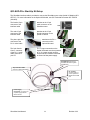
QCI-SKO-FS-v Start-Up Kit Setup
The SilverMax interface cable is provided to connect the SilverMax motor to the Optical I/O Module (QCIOPTOC). For more information on the Optical I/O Module, see QCI Technical Document QCI-TD0010
(included).
The female 15-pin
connector of the
interface cable
attaches to the 15-pin
male connector on the
SilverMax motor.
The male 15-pin
connector of the
interface cable
attaches to the 15-pin
female connector on the
optical I/O board.
The phone jack-like
connector of the
RJ-11 serial cable
attaches to the RJ-11
connector on the
Optical I/O board.
The 9-pin female
Comm connector
of the RJ-11 serial
cable connects to
your PC.
The +V Input connection on the
Optical I/O board must be connected
to V+ of a power supply and Pwr
Gnd connection must be connected
to Ground of that power supply.
SilverMax D15: Connect to
SilverMax. Be sure to tighten
thumbscrews
15-pin Interface Cable:
Connect to Optical I/O Module.
RJ-11 Cable:
Connects to RJ-11
port on Optical I/O
Module to PC COM
port.
Power Supply
Connectors: +V Input to V+
of power supply and Pwr
Gnd to Ground.
SilverMax User Manual
14
Revision 3.22
QCI-SKO-34-v Start-Up Kit Setup
The Setup for this kit is the same as the setup described above for the QCI-SKO-FS-v Start-Up Kit,
except a SilverMax Line Power Cable is Included. For more information on the Optical I/O Module, see
QCI Technical Document QCI-TD0010 (included).
The female 15-pin
connector of the
interface cable
attaches to the 15-pin male
connector on the
SilverMax motor.
The male 15-pin
connector of the
interface cable
attaches to the 15-pin
female connector on the
optical I/O board.
The phone jack-like
connector of the
RJ-11 serial cable
attaches to the RJ-11
connector on the
Optical I/O board.
The 9-pin female
Comm connector
of the RJ-11 serial
cable connects to
your PC.
The +V Input connection on the
Optical I/O board must be connected
to V+ of a power supply and Pwr
Gnd connection must be connected
to Ground of that power supply.
The 3-pin female
connector on the
SilverMax Line
Power Cable
connects to the
power connector
on the 34-frame
SilverMax motor.
The red wire at the end of the SilverMax Line Power Cable is connected to V+ of the power supply. The
black wire connects to Ground. The white wire connects to chassis ground of the power supply.
SilverMax Line Power Cable:
Connect to SilverMax.
SilverMax D15: Connect to
SilverMax. Be sure to
tighten thumbscrews
15-pin Interface Cable:
Connect to Optical I/O
Module.
RJ-11 Cable:
Connects to RJ-11
port on Optical I/O
Module to PC COM
port.
Power Supply
Connectors: +V Input to V+
of power supply and Pwr
Gnd to Ground.
Power Supply Connectors:
Required for Driver Enable.
SilverMax User Manual
15
Revision 3.22
QCI-SKO-34-65-v Start-Up Kit Setup
The Setup for this kit is similar to previously described setups, except the QCI-SK1-34-65 Start-Up Kit
contains a SilverMax 34 IP 65 Cable and no Silver Max Line Power Cable. For more information on the
Optical I/O Module, see QCI Technical Document QCI-TD0010 (included).
Connect the
female round
IP-65 connector
of the SilverMax
to the male
round connector
on the 34-frame
SilverMax motor.
The 15-pin male
connector on the
SilverMax 34 IP
65 Cable.
connects to
the supplied
Optical I/O
module.
The phone jack-like
connector of the
RJ-11 serial cable
attaches to the RJ-11
connector on the
optical I/O board.
The 9-pin female
Comm connector
of the RJ-11 serial
cable connects to
your PC.
The +V Input connection on the
optical I/O board must be connected
to V+ of a power supply and Pwr
Gnd connection must be connected
to Ground of that power supply.
The red wire at the end of the SilverMax 34 IP 65 Cable is
connected to V+ of the power supply. The black wire connects
to Ground. (BOTH these and the power connections on the
Optical I/O cable MUST be connected!)
Power Supply Flying leads: Connect
to user supplied power supply (Red to
V+ and black to Ground)
SilverMax 34 IP 65 Cable:
Connect to SilverMax.
15-pin Interface
Cable: Connect to
Optical I/O Module.
Power Supply
Connectors: Required for
Driver Enable.
SilverMax User Manual
RJ-11 Cable:
Connects to RJ-11
port on Optical I/O
Module to PC COM
port.
16
Revision 3.22
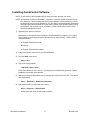
Installing QuickControl Software:
NOTE: Do not power up the SilverMax until the setup procedure specifies this action.
NOTE: QuickControl controls the SilverMax in “real-time”, it therefore needs full access to your
PC’s resources. When installing the QuickControl Software it will be necessary to close
all shared files and exit open applications. It is also highly recommended that applications
requiring large system demands be closed and any screen saver disabled when running
QuickControl. Do not power up the SilverMax or Power Interface Box until the setup
procedure specifies this action!
1) Upgrading from previous versions.
Rename the current QuickControl directory to QuickControlOld (or a name of your choice).
This will save your old version and allow QuickControl to install correctly. QuickControl is
usually installed in:
C:\Program Files\QuickControl
Rename to
C:\Program Files\QuickControlOld
2) Insert QuickControl Setup CD into your CD ROM drive.
3) From the Start menu select
Start ⇒ Run
4) Type in the setup program:
<CD Drive Letter>: setup
Follow the instructions on the screen. It is strongly recommended that you select “Typical”
installation and accept all the defaults.
5) Reboot PC: Remove all diskettes from your floppy drives and re-boot your PC. This can be
done by selecting:
Start ⇒ Shut Down – Restart the Computer?
6) Run QuickControl: From the Start menu select,
Start ⇒ Programs ⇒ QuickControl
QuickControl will come up with a blank program.
SilverMax User Manual
17
Revision 3.22
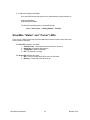
7) Initialize and Program SilverMax
Go to the QuickControl Help System for a detailed step by step procedure on:
Initializing SilverMax
Programming SilverMax
The QuickControl Help system is accessed through:
Help ⇒ Help Topics ⇒ Getting Started – Tutorials
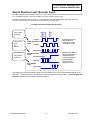
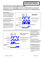
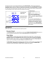
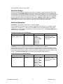
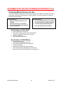
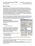
SilverMax “Status” and “Comm” LEDs:
There are two LEDs on the back of the SilverMax motor that are used for motor status and
communications indication.
The Red LED indicates in four ways:
1. A Short Flicker = Successful communications to the motor.
2. Bright ON = Incomplete transmission.
3. ½ Bright ON = Motor in Idle state.
4. OFF = A program is running.
The Green LED indicates two ways:
1. ON = Power is present and DSP is active on the Motor.
2. Blinking = There was a fault at power up.
SilverMax User Manual
18
Revision 3.22
UPGRADING FROM QUICKCONTROL 3.1 TO 3.2
What is New?
SilverMax Initialization Wizard
Rev 3.1’s Initialize SilverMax screen has been replaced with the much simpler SilverMax
Initialization Wizard. Initialization files have been upgraded to standard program Files (.QCP).
See SilverMax Initialization for details.
Where Do I Set Motor Voltage?
You no longer have to manually set the motor’s supply voltage. QuickControl automatically
reads the voltage from the SilverMax and modifies the Initialization file for you The motor
voltage can still be set manually by pressing the Options button.
How Do I Edit the Initialization Parameters?
The initialization parameters are accessed through the Initialization Parameter Browser.
Can I Still Use My Old Initialization Files?
Although existing initialization files can still be used by way of the “Rev 3.1 Tools” menu item,
it is suggested you create new ones with the new wizard. The old files do not have access to
any of the new initialization commands that have been developed(compare all the parameters
in the browser to what you use to have!).
Default Start Address
The Default Start Address is the place in non-volatile memory where the first program gets
stored. In other words, this is the address the initialization program “runs” when it is finished.
In Rev 3.1 this was set to 110. In Rev 3.2 this has been increased to 512 do to all the new
initialization options we have added. If you upgrade to the SilverMax Initialization Wizard, this
will be transparent to you and all your old programs will work just fine. If you choose to
continue to use the older initialization files, you will have to set the Default Starting Address to
110. This can be done by pressing the Options button and entering 110 into the Default
Starting Address field. Exit out of the SilverMax Initialization Wizard and use your old
Initialization files from the rev 3.1 Tools menu.
SilverMax User Manual
19
Revision 3.22
SilverMax Control Panel
The rev 3.1 Motion Tuning and Jog SilverMax screens have been replaced with the SilverMax
Control Panel. See QuickControl Help System for a detailed description of this screen.
The major additions include:
Device Status: Voltage (actual voltage measured by SilverMax)
Device Status: Temperature (actual temperature measured by SilverMax)
Inputs/Outputs: Analog Inputs (actual voltage measured by SilverMax)
Single Step/Trace/Breakpoint
Two new buttons have been added to the program Info Toolbar, Trace and Single Step. Using
these buttons you can now single step through your program. A Breakpoint can be set on any
line by selecting:
SilverMax User Manual
20
Revision 3.22
Programs ⇒ Toggle Breakpoint
See the QuickControl Help system for a detailed explanation of these new features.
QuickControl Rev 3.1 Tools
All your old favorites can still be accessed by selecting:
Tools ⇒ Rev 3.1 Tools
SilverMax User Manual
21
Revision 3.22
SILVERMAX INITIALIZATION
Each SilverMax unit contains internal Initialization Programs that set up the operational values and
constants for the motor at power up. By default the Initialization Programs are downloaded into the
non-volatile memory at location “0”. User programs start at “512”.
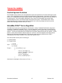
SilverMax Factory Default Initialization.qcp
The program “SilverMax Factory Default Initialization.qcp” is designed for use with the SilverMax
Initialization Wizard tool. This program sets up all motor parameters. The program can also be edited
manually to add more commands or modify those that are not shown in the “Initialize” tool. Typically
this file should be saved to a different name after it is edited or used for initializing a motor. The
wizard can be accessed by selecting:
Tools ⇒ SilverMax Initialization Wizard
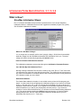
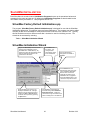
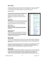
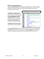
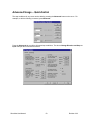
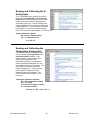
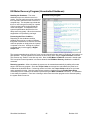
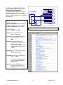
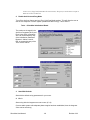
SilverMax Initialization Wizard
Begins the Download process that loads
and stores the initialization into the
SilverMax’s Non-Volatile Memory. By
default, the motor will automatically reboot
after the download to allow the new
parameters to take affect..
Press Exit to exit
the wizard. Your
changes will be
automatically saved
to the selected file.
See the QuickControl
Help system for details on
Options.
Press Interview to have
QuickControl walk you through
every initialization parameter.
Note as each command is
presented, its location in the
initialization file is highlighted.
Press the Cancel button on any
command to stop the interview.
All the parameters are stored in the
displayed initialization file. Changes
made here can be saved to the file by
pressing the Save or Save As button.
A new file can be opened by pressing
the Open button.
SilverMax User Manual
The initialization parameters are
accessed through the Initialization
Parameter Browser. Editing the
commands through the browser is the
same as editing them in the QCP file.
22
Revision 3.22
The wizard provides a friendly way of editing the initialization program file (i.e. SilverMax Factory
Default Initialization.qcp). Note: when the wizard is launched, the initialization file is opened in the
background and stays open after the wizard is closed. Editing a SilverMax command in the wizard is
the same as editing it in the QCP file.
If the factory defaults are acceptable (described below), turn the SilverMax on and press the
Download… button to initialize the attached SilverMax. When the “Download Complete” message
appears, close the wizard and start using your SilverMax.
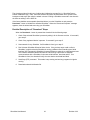
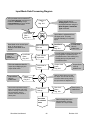
Detailed Description of “Download” Steps
When the Download… button is pressed the wizard will do the following steps:
1. Check if the selected SilverMax is present by asking it for its firmware revision. If successful,
go to step 5.
2. Check if any registered device is present. If successful, go to step 5.
3. Scan network for any SilverMax. If a SilverMax is found, go to step 5.
4. Run Unknown SilverMax Wizard to find a device. If the previous steps could not find a
SilverMax, it might be that the SilverMax is running a different Serial Interface (see Serial
Interface (SIF) command in SilverMax Command Reference manual) or a different baud rate.
The Unknown SilverMax Wizard will walk the user through a procedure to establish
communications with a SilverMax of unknown serial interface, baud rate and ID. If no
SilverMax is found, the wizard will notify the user that the download has failed.
5. Send Stop (STP) command. This makes it stop moving and end any programs it might be
running.
6. Download selected initialization file.
SilverMax User Manual
23
Revision 3.22
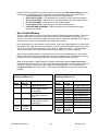
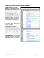
SilverMax Factory Default Initialization File - Detailed
The Initialization program file contains the following programs:
Main Init
The main initialization program which contains all of the initialization commands. This is described in
great detail below.
Startup Recovery
Startup Recovery is used during the factory default initialization to indicate an error has occurred. The
program will cause the Status LED to pulse.
Kill Motor Recovery
This program gets called whenever a condition in the Kill Motor Recovery (KMR) command is met.
The user may modify this program if special processing is required.
For example, if the user wanted the SilverMax to set an error output anytime it detected a “jam”. They
would first set the “Moving Error” in the Kill Motor Conditions (KMC) command and then add a Set
Output Bit (SOB) command to the Kill Motor Recovery program.
Power Low Recovery
The user may modify this program if special processing is required on a Power Low condition. For
example, the user may want to save the SilverMax's current position.
SilverMax User Manual
24
Revision 3.22
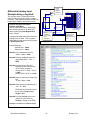
Main Init[0]
The Main Initialization program is broken up into the following sections. Each section editable by
the SilverMax Initialization Wizard is a branch on the wizard’s Browser. Please refer to the
Command Reference for a detailed description of the individual commands.
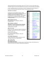
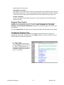
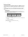
Communications
At the very beginning of power up the most vital thing to do
is establish serial communications with SilverMax. Without
this the user may be unable to communicate with
SilverMax, which will make diagnosing a problem or
configuring the motor difficult. This section is the first to
execute.
IDT: Identity
(default: “16”)
The motor Identity command must be the first command in
the first program. If it is not present no initialization will take
place. This is to prevent an non-initialized motor from
attempting to initialize from blank non-volatile memory.
PRO: Protocol:
(default: 8-Bit ASCII)
8-Bit ASCII is the most common protocol used and the
easiest to communicate with SilverMax using a standard
serial UART.
SIF: Serial Interface
(default: Auto)
SilverMax can operate using either RS-232 or RS-485. In
Auto, QuickControl will query SilverMax on its current SIF
and set this command to match. This command can also
be edited from the Serial Interface field of the SilverMax
Initialization Wizard’s Option screen.
BRT: Baud Rate
(default: 57.6K)
The serial communications baud rate can be set to lower values such as 9600 or 19200 baud for
slower host communications ports or to higher values such as 115200 or 230400 for high speed
systems. 57.6K is recommended for RS-232 and RS-485, while 19.2K is recommended for RS232 multi-drop.
Please note, this command has no affect on the PC’s baud rate. If you download an initialization
program with a different baud rate than your PC, you will loose communications with the
SilverMax as soon as the SilverMax reboots. To re-establish communications, change the PC’s
baud rate to match the new SilverMax baud rate (Setup⇒Comm Channels).
ADL:ACK Delay
(default: Auto)
Normally SilverMax will immediately acknowledge a received command. It can do this within 120
microseconds after receiving the last character in a command packet. This is sometimes too fast
for the host PC or PLC when running on an RS-485 or RS-232 network. SilverMax may be
sending its acknowledge packet before the host has switched out of transmit mode. This
condition will cause a loss of characters. Setting the ACK Delay will allow SilverMax to delay a
SilverMax User Manual
25
Revision 3.22
specified period before the acknowledge packet is sent. NOTE: A non-zero ACK Delay puts a
SilverMax using RS-232 into RS-232 Multi-Drop mode (See the Command Reference for details).
In Auto, QuickControl will set the ACK Delay to 2.4ms (20 120uSec ticks) if the SilverMax is in
RS-485 or RS-232 Multi-Drop mode and to 0ms if it is in straight RS-232 mode.
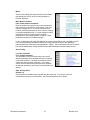
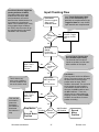
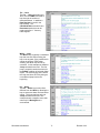
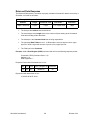
Startup Error Conditions
At power-up or if the initialization routine is called,
SilverMax will verify that the input voltage and the motor
temperature are at an acceptable level before
proceeding with the motor initialization. If the voltage or
temperature is out of range the “Startup Recovery”
program will be executed that will aide in the diagnosis
of a startup problem.
KMR: Kill Motor Recovery
Run “Startup Recovery” program if a Kill Motor
Condition occurs.
KMC: Kill Motor Conditions
Set KMC to over temp only (over voltage is always an
active KMC). If an over temperature or over voltage
condition exist, the SilverMax will now execute the
“Startup Recovery” program.
ERL: Error Limits
Disable error limits at startup to suppress nuisance error
messages. Until the motor has torque, it will probably
have movement errors.
PLR: Power Low Recovery
Run “Startup Recovery” program if a low power
condition occurs.
CAI: Calibrate Analog Input
Calibrate analog input channels using factory stored
scale factor stored in non-volatile memory.
TQL: Torque Limits
GOL: Go Open Loop
SLC: Single Loop Control
Start motor/encoder alignment by setting torque to 0 and entering Open Loop and Single Loop
modes (see below for more detail on Motor/Encoder alignment).
SilverMax User Manual
26
Revision 3.22
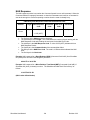
Motor
These motor settings are required before the SilverMax
can attempt any kind of move including the Motor to
Encoder alignment.
MCT: Motor Constants
PAC: Phase Advance Constants
Each SilverMax is set up with unique motor parameters
that program it for operation at a set voltage. The most
common voltages are 12, 24, 36 and 48. QuickSilver
Controls provides parameters for these common voltages
in complete initialization files. For other voltages contact
QuickSilver Controls’ Product Support to obtain
parameters for any voltage between 12 and 48. These
parameters should not be edited manually.
In Auto, QuickControl will query SilverMax for its current voltage and set this command to match.
If you are programming SilverMax at a different voltage than will be used in the application,
manually set these commands to the application’s voltage. These commands can also be edited
from the SilverMax Motor Voltage field of the SilverMax Initialization Wizard’s Option screen.
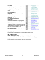
Servo Tuning
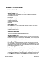
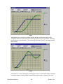
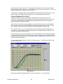
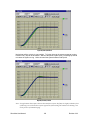
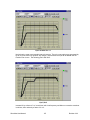
LC: Filter Constants
CTC: Control Constants
The SilverMax PVIA servo control loop is set up with
default parameters which will allow the motor to operate
under most conditions. We have found that the factory
values work well over 80% of the time. If not, these
values can be modified using QuickControl to establish
the desired operational control (see Tuning SilverMax for
details).
GOC: Gravity Offset
(default = 0)
Gravity offset is a constant torque injected after the servo loop. A none-zero value will
compensate for gravity on vertical loads. See Command Reference for details.
SilverMax User Manual
27
Revision 3.22
Motion
This section contains parameters affecting general
SilverMax motion. They are all editable from both the
SilverMax Initialization Wizard or from the program file
directly (i.e. double click on the command).
DIR: Direction
TQL: Torque Limits
AHC: Anti-Hunt Constants
AHD: Anti-Hunt Delay
SCF:S-Curve Factor
For details on these commands, see the Command
Reference.
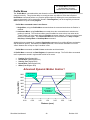
Motor/Encoder Alignment Routine
Before the SilverMax can be put into closed loop
mode, an alignment between the motor rotor and the
Encoder must be established. This is done using one
of two different algorithms that will automatically
perform this task. Standard alignment is selected
when very low residual torque is on the motor at
startup and low torque (< 5% of Max) is required to
move the load at low speed (< 1 RPM). The Complex
alignment is used with high residual torque or when
high breakaway torque (stiction) is present during
startup.
Standard alignment (Factory Default)
The standard alignment routine simply fixes a known vector (phase value) in the stator windings,
clears the encoder count register, then puts the motor into closed loop mode. This is typically
done using a high winding current to ensure that the motor rotor aligns itself to the encoder. This
routine always takes a pre-determined period of time.
Complex alignment (SilverMax Factory Complex Initialization.qcp)
For loads that have a very high frictional content, the complex alignment routine offers a more
accurate system of aligning the encoder to the motor. The complex routine spends more time to
make sure that the rotor and encoder are aligned before going into closed loop mode. The timing
can vary and therefore the SilverMax should be polled for Program Complete before attempting
to operate the motor.
SilverMax User Manual
28
Revision 3.22
Error Limits
Good practice requires that operational limits and
error conditions be set up prior to motor operation.
Setting up these parameters can provide safer
operation or may prevent damage to the motor and
system.
LVT: Low Voltage Trip
(default=10V)
Set point at which SilverMax will execute the “Power
Low Recovery” program.
OVT: Over Voltage Trip
(default=51V)
MTT: Maximum Temperature Trip
(default=70C)
Set points at which SilverMax will disable its driver
and execute the “Kill Motor Recovery” program.
ERL: Error Limits
(default = no limits)
The difference between the “Actual Position” and the
“Target Position” can trigger an error flag or “Kill” the
motor. The acceptable limits are set here.
KDD: Kill Disable Drivers
Drivers will be disabled when a Kill Motor Condition
occurs.
KMR: Kill Motor Recovery
Run the program “Kill Motor Recovery” any time a Kill Motor Condition occurs.
KMC: Kill Motor Conditions
(default: Kill only on over-temp)
Set KMC to over temp only (over voltage is always an active KMC). If an over temperature or
over voltage condition exist, the SilverMax will now execute the “Kill Motor Recovery” program.
PLR: Power Low Recovery
Run the “Power Low Recovery” program if a low power condition occurs.
SilverMax User Manual
29
Revision 3.22
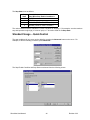
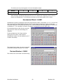
Misc
DIF: Digital Input Filter
(default=10ms)
DIF is a digital filter on all input lines (de-bounce).
This only affects the basic digital inputs and does
affect the analog inputs, external encoder signals or
step and direction signals.
DDB: Disable Done Bit
MDC: Modulo Clear
Special output modes set to their default states. See the Command Reference for details.
LRP: Load and Run Program
(default=512)
After the initialization is complete, SilverMax can begin execution of a user defined program.
User programs can be created using QuickControl’s program editor (QCP). This command can
also be edited from the Default Starting Address of the SilverMax Initialization Wizard’s Option
screen.
The SilverMax Initialization Wizard requires this line to exist in all init program files. If your
application does not require a user program, Check the Erase Application box of the SilverMax
Initialization Wizard’s Option screen.
Tools⇒SilverMax Initialization Wizard⇒Options⇒Erase Application.
This will write a single line program at the Default Starting Address (512) consisting of the END:
Program End command. When SilverMax reboots, it will execute its initialization program and
them load and run the program at 512 which will be an END command. SilverMax will now be in
host mode awaiting commands over the serial port.
SilverMax User Manual
30
Revision 3.22
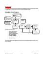
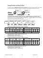
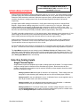
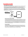
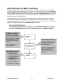
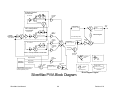
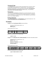
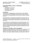
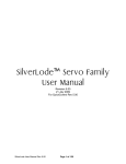
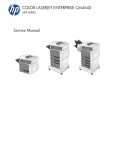
OVERVIEW
The SilverMax Motion Control System integrates all of the traditional modules for motion control needed
to provide rotary position and velocity control in one single mechanical package.
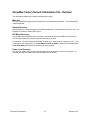
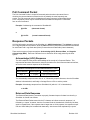
SilverMax Block Diagram
Non-Volatile
Memory
8K Byte (32K Option)
Serial
Communications
RS-232 or RS-485
7 Digital I/O &
4 Analog inputs
Command
Processor
TI - DSP
Trajectory
Generator
Program
Buffer
200 Words
Servo
Control
Loop
SilverMax elements include:
•
•
•
•
•
•
•
•
•
Motor Driver/
Commutation
Sine/Cosine
High Pole
Count
Brushless
Motor
Position
Feedback
4K-16K Count
Optical Encoder
Serial Communications
Command Processor
Digital I/O & Analog Input
Non-Volatile Memory
Trajectory Generator
Servo Control Loop
Motor Driver/Commutation
Brushless Motor
Position Feedback
All of these elements work together to form an easy-to-use system that requires only DC power
for full operation.
SilverMax User Manual
31
Revision 3.22
Serial Communications
The serial communications furnish SilverMax with an RS-485 multi-drop or RS-232 communications
capability at a selectable baud rate (default 57.6K baud). Two different communications protocols are
available depending on the system design needs. The serial communications are used to initialize the
SilverMax in both network and stand-alone operations. SilverMax’s companion product, QuickControl,
may be used to quickly prototype motions, initialize and program SilverMax using the serial
communications.
Communication Hardware
SilverMax is programmable with two different hardware interfaces for serial communications. RS485 or RS-232 is selectable by initializing the SilverMax for the desired hardware interface.
RS-485 Multi-Drop
RS-485 is a two-wire serial communications hardware interface. By design, RS-485 can connect
up to 32 serial devices in parallel on the same two wires. This provides the ability to network a
number of SilverMax units together on a common serial connection. SilverMax is designed to
work on a network with its individual addressing and communications protocol. This offers
greater simplicity in harnessing and communicating to a number of SilverMax units on a system.
If a host controller is used that only supports RS-232, an RS-232 to RS-485 converter can be
used that will allow the host to communicate with a SilverMax RS-485 network.
RS-232
RS-232 offers the easiest way to connect SilverMax to a host computer. Through appropriate
cabling, a SilverMax can be directly connected to an RS-232 serial communications port. A
drawback of RS-232 is that typically only one SilverMax can be connected to the serial port at a
time. If a network is required, the RS-485 version with a converter board (RS-232 to RS-485)
can be used.
RS-232 Multi-Drop
SilverMax is also able to work on an RS-232 multi-drop network with a limited number of nodes.
The number of nodes is limited by the communications drivers and cabling requirements
(typically no more than 5). This is a great way of attaching multiple SilverMax to a standard or
PLC serial port (i.e. COM1).
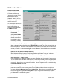
Communication Protocols
A simple 9-bit protocol can be used where systems require high data rates, deterministic operation
and robust error checking. The 9-bit protocol transmits data in binary form, which minimizes the
number of bytes required for a command. An 8-bit ASCII protocol can be used where generic serial
communications is required and speed or determinism of transmission is not critical. SilverMax E
Series motors are shipped from the factory with both protocols available. The desired protocol is
selected when first initializing a SilverMax unit. (For more information see the 9-Bit Binary
Communications and the 8-Bit ASCII Communications sections below)
Command Processor
The Command Processor interprets each command sent to the SilverMax using the serial
communications and then initiates the desired operation. The Command Processor checks each
received command to verify that proper syntax is used. If a command is complete, the Command
Processor will perform all the necessary functions required to set up and execute the command. If a
command is incorrect, the Command Processor will issue an error code through the serial
communications. The Command Processor uses a Command Buffer to store and execute commands.
SilverMax User Manual
32
Revision 3.22
Digital I/O
To give the SilverMax more PLC-like features, there are seven fully programmable digital I/O lines. Each
line is software configurable to be a digital input, a digital output or dedicated to a special function. These
lines can be configured “on the fly”. Digital outputs can be set into tri-state mode, allowing the lines to be
used as both an output and input at the same time.
Using a variety of dedicated modes, these I/O lines can also be used for external encoder input for
electronic gearing or camming operations. Inputs can be Step and Direction, A/B quadrature or Step
up/down. An external encoder input is provided for dual control loops that enable position control of
external mechanisms using a second encoder. The E Series can also output Step and Direction, A/B
quadrature or Step up/down from its internal encoder.
To supplement the serial communications, digital inputs can also provide simple control over SilverMax
operation. SilverMax programs that use the digital inputs for program flow control can be written and
downloaded into the motor. Using the digital inputs, the SilverMax can operate independent of any other
controlling device. Home or position sensors can also be connected to the inputs allowing end of travel
control.
Analog Inputs
In addition to the digital I/O, SilverMax motors accept analog input. Four analog inputs share four digital
I/O lines and will accept 0 to +5 volt analog signals. Analog inputs can be used for control of the motor’s
position, velocity, torque or other software programmable operations.
Non-Volatile Memory
SilverMax includes on-board Non-Volatile Memory. The Non-Volatile Memory is used to permanently
store SilverMax programs and data. The stored programs can then be used for power-on initialization or
for user defined autonomous operation. programs that are stored in Non-Volatile Memory can be recalled
by SilverMax for execution even after power has been removed. Stored programs can be recalled and
executed using the Serial Communications or Digital Inputs. At power-on, the program stored in the first
memory location (“0”) is automatically re-called and executed. This feature allows a SilverMax to operate
autonomously or from a Host-controlling device.
Trajectory Generator
The trajectory generator is a significant component of SilverMax. It enables trapezoidal and S-Curve
shaped moves that are defined by either the Relative distance to move or the Absolute position.
Motion profiles can be defined either by acceleration and velocity, or by the total motion time plus the
ramp time. The generator can also stop motions by using a complex Stop on digital input algorithm.
The generator monitors both the running position-error value and the holding position-error value, and will
automatically set a status bit when an error limit is exceeded. The running and holding error status bits
can optionally halt a motion in process by shutting down the motor. The trajectory generator can be fed a
step and direction input to permit interfacing a SilverMax with an external indexer.
Servo Control Loop
The Servo Control loop implements a Patented Control Algorithm that includes filtering on the Velocity
& Acceleration terms. This allows Lead/Lag compensation to be employed for higher performance loops.
Also included are a Velocity feed-forward term and an additional Acceleration Feed-Forward term for
active damping term. The control algorithm provides gain terms for each of the control parameters and
filter time constants for velocity and acceleration feedback filters.
SilverMax User Manual
33
Revision 3.22
Motor Driver/Commutation
The motor driver is matched to the selected motor and power supply voltage by using motor setup
parameters that are pre-set at the factory. This means that there is usually no work required by the user
to prepare the motor for operation. The parameters have been optimized to produce maximum
performance under a wide range of conditions. Motor commutation is accomplished using the internal
encoder for motor phase information. Sine and Cosine signals are used to drive the two phases of the
motor thus producing a quiet, low cogging motor output.
Brushless Motor
The Brushless Motor is a high pole count Permanent Magnet AC Synchronous Motor. The “magnetic”
gearing of a high pole count motor yields high torque in a small package. This type of motor provides for
the use of a special “anti-hunting” mode in which the motor windings are driven to hold the motor at the
desired position without hunting.
Position Feedback
The Position Feedback furnishes the control system with precise information about the motor position and
velocity. The Position Feedback can resolve position information of 4000 (8000 and 16000 on some
models) counts per revolution. The position feedback also provides an index pulse for each revolution of
the motor.
SilverMax User Manual
34
Revision 3.22
SILVERMAX MOTION COMMANDS
SilverMax can operate using different motion commands that provide options to meet a variety of motion
control needs. SilverMax can be controlled internally or externally depending on the system requirements and
can operate in different modes depending on the type of motion needed.
Internal Control
Standard Motion
(Trapezoidal)
Velocity Mode
Profile Move
(Any Shape)
Internal Control
(Uses Trajectory
Generator)
Uses the SilverMax internal calculation machine to perform the
motion
External Control
Step & Direction
Mode
Analog Input Mode
(Velocity & Position)
External Control
(Uses External
Controller)
Uses an External Controller or signal source for motion
control
SilverMax User Manual
35
Revision 3.22
Standard Motion & Profile Move Commands
Internal Trajectory Control
Built into SilverMax is a full-featured trajectory control generator. The generator can algorithmically
calculate and create S-Curve and trapezoidal motion profiles. The motion profiles are built from
parameters such as distance, acceleration and velocity provided by the user. The following is a
discussion on the various command types that provides the user with a number of different techniques for
creating a motion profile.
Standard Motion Profiles
Standard Motion commands provide a basic “Acceleration - Velocity - Deceleration” (Trapezoidal)
shaped move that goes a given Relative Distance or to a defined Absolute Position. Standard motions
use both Linear and S-Curve acceleration and deceleration for the excellent control of the load under
all conditions. Once initiated these moves cannot be altered dynamically.
Standard Motion commands come in three flavors:
•
•
•
Parameterized: Where all parameters are sent with the command.
Registered: Where the Distance or Position parameters are located in a Data Register.
Extended Registered: Where all of the move parameters except for the Stop Conditions are
located in Data Registers
Each flavor has two different parameter types:
• Absolute or Relative
The move runs to a given Absolute Position or a Relative Distance.
• Velocity or Time
The motion profile uses Acceleration and Velocity or Acceleration Time and Total
Time for the speed parameters.
SilverMax Standard Motions
1200
Full S-Curve
2 x Acceleration
As Linear Ramp
Velocity (RPM)
1000
800
600
400
Full S-Curve
Same Acceleration
as Linear Ramp
Linear
Acceleration
200
0
0.000
0.050
0.100
0.150
0.200
0.250
0.300
0.350
0.400
Time (seconds)
SilverMax User Manual
36
Revision 3.22
“Relative” Move Commands
Relative Move commands will cause SilverMax to move a specified distance from its current position.
This is a relative position command meaning it will always move the specified distance away from its
current position. Move Relative commands come in following types.
Move Relative, Velocity Based (MRV)
Three parameters are entered - Distance, Acceleration & Velocity. This is the most
straightforward command type.
Register Move Relative, Velocity Based (RRV)
Three parameters are entered – Data Register, Acceleration & Velocity. The Distance
parameter is the number of a special internal register called a Data Register. The Data
Register is used for the distance value. The value entered in the Data Register is still in
counts. The other parameters are the same as the MRV command. This command allows
the user to modify the distance value without having to change the command when used as
part of a program.
Extended Register Move, Velocity Based (XRV)
One parameter is entered – the Starting Data Register. Only the Distance register location
is sent as a parameter, the Acceleration & Velocity must be stored in two successive
Registers.
Move Relative, Time Based (MRT)
Three parameters are entered - Distance, Acceleration Time & Total Time. This command
makes doing time-critical profiles easy. When the desired time to make the move is fixed,
using this command will cause SilverMax to make the move, no matter the distance (within
limits), in the exact time specified. This is very useful when a number of different axes must
be precisely coordinated in time.
Register Move Relative, Time Based (RRT)
Three parameters are entered – Data Register, Acceleration Time & Total Time. This
combines the RRV and MRT types parameters together.
Extended Register Move Relative, Time Based (XRT)
One parameter is entered – the Starting Data Register. Only the Distance register location
is sent as a parameter, the Acceleration Time and Total Time must be stored in two
successive Registers.
SilverMax User Manual
37
Revision 3.22
“Absolute” Move Commands
Absolute Move commands will cause SilverMax to move to a specified position from its current
position. This is different from the “Relative” commands that move a given distance rather than to a
specific position. SilverMax keeps track of its current position (as indicated in counts) by continuously
monitoring its Internal Encoder. When SilverMax moves, the current position is updated by the
number of Encoder counts, negative or positive, encountered during the move. When a Move Absolute
command is used, SilverMax calculates the number of counts (or distance) required to move to the
specified position. If the position given in the command is the same as the current position, SilverMax
will not move since it is already at the specified position. Using this command helps prevent over-travel
when a command is sent twice by mistake. This command is also useful in setting up Registered
positions that can be referenced from the Dedicated or Data Registers. Move Absolute commands
come in following types.
Move Absolute, Velocity Based (MAV)
Three parameters are entered - Position, Acceleration & Velocity. This is the basic
command type for absolute moves.
Register Move Absolute, Velocity Based (RAV)
Three parameters are entered – Data Register, Acceleration & Velocity. The Data
Register parameter is the Data Register that is used to fill in the position value. The value
entered in the Data Register remains in counts. The other parameters are the same as the
MAV command. This command allows the user to modify the position value without having to
change the command when used as part of a program.
Extended Register Move Absolute, Velocity Based (XAV)
One parameter is entered – the Starting Data Register. Only the Position register location
is sent as a parameter, the Acceleration & Velocity must be stored in two successive Data
Registers.
Move Absolute, Time Based (MAT)
Three parameters are entered - Position, Acceleration Time & Total Time. This command
makes doing time critical profiles easy. When the desired time to make the move is fixed,
using this command will cause SilverMax to make the move, no matter the position (within
limits), in the exact time specified. This is very useful where a number of different axes must
be precisely coordinated in time.
Register Move Absolute, Time Based (RAT)
Three parameters are entered – Data Register, Acceleration Time & Total Time. The Data
Register specified holds the Position parameter. The other two parameters are the same as
MAT.
Extended Register Move Absolute, Time Based (XAT)
One parameter is entered – The Starting Data Register. Only the Position register location
is sent as a parameter, the Acceleration Time and Total Time must be stored in two
successive Data Registers.
SilverMax User Manual
38
Revision 3.22
Moves Using Data Registers
A number of the Standard Motion commands can use data registers for their parameter information.
This allows SilverMax (and the user) more flexibility in programming a Motion. The most common is
when Motion commands are used as part of a program and the parameters need to change
depending on operating conditions.
Homing to Encoder Index.qcp
The Example at the Right shows a homing
program that uses the Internal Index
sensor to stop the motor at a precise onceper-revolution location. In this example line
#7 uses a Registered Move Absolute,
Velocity Based (RAV) command. The
Data Register is set to #2 “Last Index”,
which is the location of the motor the last
time the Index was encountered. The
previous move command allowed the
motor to find the Index before it stopped.
The RAV command will cause the motor to
move directly to the “Last Index” position
without having to do any extra calculations.
SilverMax’s Extended Register Move commands give the user access to all of the move parameters
as Data Registers. With this, not only the Position or Distance parameters can be changed outside
the command; Acceleration and Velocity can also be modified as Data Register values. This gives
the ability to modify these parameters based on system needs prior to their use in a program.
SilverMax User Manual
39
Revision 3.22
See Profile Move Commands in
the SilverMax Command
Reference for more information
Profile Moves
The “Profile Move” commands add a new dimension to SilverMax by allowing the move parameters to be
changed on-the-fly. This gives the ability to create just about any shape of move that is required.
Profile Move commands perform very complex profile shapes by allowing the move parameters to be
changed dynamically. Move parameters (stored in “Data Registers”) can be changed by an external
Host controller or by an internal program.
Profile Move commands come in two flavors:
1. Single Move; using the Profile Move command where the command ends when the Position is
reached.
2. Continuous Move; using Profile Move command where the command doesn’t end when the
position is reached. The Continuous Move puts SilverMax into a move that, even when at the
Target Position, will move again when the Position parameter changes – there is no need to issue
the move command again. The Continuous Move can be terminated with a “Stop on Input”,
Halt, Stop, Velocity Mode or Hard Stop Move command.
Added with these commands is a separate Deceleration parameter for providing different acceleration
and deceleration profiles. Also added is an Offset parameter, which causes SilverMax to move an
“offset” distance after a “Stop on Input” condition is met.
Profile Move commands use ONLY Linear acceleration and deceleration.
All Profile Move commands use Data Registers for parameter storage. The Profile Move commands
use five parameters stored in registers #20 to #24 for all moves:
•
•
•
•
•
Position (Data Register #20)
Acceleration (Data Register #21)
Velocity (Data Register #22)
Deceleration (Data Register #23)
Offset (Data Register #24)
Advanced Dynamic Motion Control !
1600
Change Velocity
On-The-Fly
Separate
Deceleration
Parameter
1400
Velocity (RPM)
1200
1000
800
Control
Deceleration or
Acceleration
600
400
200
0
0.00
0.50
1.00
1.50
2.00
2.50
3.00
Distance (revs)
SilverMax User Manual
40
Revision 3.22
Velocity Mode Control
From a Host Controller or using an internal program, Velocity profiles can be created on SilverMax
using the Velocity Mode, Immediate Type command (Host Controller) or the Velocity Mode,
program Type (Internal program) that will allow changes in velocity at desired time intervals. This
allows the creation of a complex shaped profile where different velocities are required at different
times during the move. In this mode distances cannot be controlled precisely, therefore other
operations such as a final MOVE ABSOLUTE command must be used for precise positioning. (Use
the Profile Move commands for complex position control)
Velocity control can be set so that the SilverMax runs at a constant velocity for an indefinite period of
time. The ERROR LIMITS command may be used in conjunction with this command to prevent
excessive wind-up under conditions where the velocity cannot be maintained. (See Error Limits
Command for more details; also see Drag Operation below)
Torque Control (Using Velocity Mode)
The Torque value can be set for the desired amount under all types of move commands. If a pure
torque mode is required, the Velocity Mode commands can be set so that the SilverMax will
attempt to run at desired maximum speed (Full speed = 4000 RPM). The ERROR LIMITS
command must be used as mentioned above to prevent excessive wind-up. Torque can then be
set using the Torque Limits command to a desired value giving a constant torque output on the
motor shaft.
SilverMax User Manual
41
Revision 3.22
External Trajectory Control
If the need arises for external control of a motion profile SilverMax can be placed in optional modes which
will accept external control input.
Scaled Step and Direction (Electronic Gearing)
Step and Direction mode allows input of external signals that can be designed to provide the desired
motion control profiles. In this mode, two digital input lines are used to input a step pulse and
direction state into the SilverMax (A/B Quadrature is also allowed). SilverMax has an internal
counter that keeps track of the number of step pulses. If the direction state is a “1”, the counter
counts up; if the state is a “0”, the counter counts down. Every 120us SilverMax checks the counter
value and updates its target value with the latest counter value. In this way SilverMax tracks the
step count so that its position will match the desired count. A scaling factor allows the user to scale
the input pulses by multiplying or dividing the input pulses. The input can be multiplied by up to 32
times or divided by up to 1024.
Position Input Mode
When the Position Input Mode (PIM) command is used, SilverMax will take Target (desired
position) information from a predefined Data Register and track the value contained in it. This is
done every servo cycle (120 usec.) providing an 8K Hz update rate.
The Target Register can be loaded from many sources, including the Serial Interface or the
Analog Inputs. Using the Serial Interface a Host controller can “stream” Target information to the
SilverMax using the Write Register, Immediate Type (WRI) command. The Serial Interface can
run at a BAUD rate of up to 230K bits per second which allows sending new data at approximately
500 times per second. (This assumes continuous data feed to the Serial Interface).
Using the Analog Inputs, an Analog signal can be used to send the Target information to the
predefined Data Register. The Analog Input is converted using an Analog to Digital Converter
(ADC) to a 10-Bit digital number. The number is filtered to eliminate “noise”, then scaled to a 16-Bit
value and placed in the Data Register. This is done at the 8K Hz update rate of the servo system.
(See ANALOG CONTINUOUS READ command for more information)
Both Input sources are put through a data processing algorithm to allow Offsetting, Limiting and
Scaling of the data source. (See Using Input Modes in the SilverMax Command Reference for
more information)
Velocity and Torque Input Modes
The Velocity Input Mode (VIM) and Torque Input Mode (TIM) commands use the same input
sources and techniques as the Position Input Mode (PIM). VIM and TIM will use the Target
Register for “Velocity” and “Torque” respectively.
SilverMax User Manual
42
Revision 3.22
USING INPUTS TO STOP MOTIONS
Commands that use inputs to stop their operation can use a Standard or Advanced process in detecting
desired input stop conditions. Eight Digital Inputs are available for evaluation. One of the inputs is a dedicated
internal input that is tied to the Internal Encoder Index sensor. The index sensor is able to detect a single
count position out of the 4000 in one revolution (one count in one revolution). This input is referred to as the
“Index”. The other seven inputs are user configurable. These inputs can be Home sensors, End of Travel
sensors or even digital inputs from a PLC or Master Controller. Whatever the inputs are, they can be used
either alone or together to affect the operation of the motion commands. The following shows the process that
is used for sensor detection and utilization.
SilverMax commands can be entered in either their native form or from QuickControl. The native form is
required when commanding the SilverMax from a host controller such as a PC or PLC. QuickControl would be
used for any stand alone application. Both interfaces are described below.
Standard Usage – Native SilverMax
All eight Digital Inputs plus a few internal conditions are available with Standard usage. Input checking is
done on only ONE selected input
By using a negative number in the Stop Enable parameter, the motion commands can look at a single
Digital Input or Internal Status Condition to stop a motion. This is the simplest usage for stopping on Input.
The following is a list of possible inputs.
Stop Enable Code
0
-1
-2
-3
-4
-5
-6
-7
SilverMax User Manual
Input Source
Description
Do not Check for Input
I/O #1
I/O #2
I/O #3
I/O #4
I/O #5
I/O #6
I/O #7
Current Index Sensor –
(Future implementation, use –
9 or –10)
Internal Index Sensor
External Index Sensor
Hardware
“
“
“
“
“
“
-8
“
-9
-10
“
“
-11
-12
-13
-14
Internal Status
“
“
“
43
Moving Error Status
Holding Error Status
Trajectory Generator Active
Delay Counter Active
Revision 3.22
The Stop State is set as follows:
Stop
State
0
1
2
3
Description
Stop When Stop Enable Condition is
FALSE
TRUE
FALLING (TRUE to FALSE Transition)
RISING (FALSE to TRUE Transition)
The value entered is used to evaluate the “TRUE” condition for stopping. If, for example, a motion needs to
stop with input #4 in logic high (+5 volts on input) a “1” should be used for the Stop State.
Standard Usage – QuickControl
The stop conditions for any move can be edited by pressing the Advanced button on the move. For
example, to edit the following command, press Advanced.
The Stop Enable Condition and Stop State are selected from the following screen.
SilverMax User Manual
44
Revision 3.22
Advanced Usage – Native SilverMax
Only four inputs are available with the Advanced usage. The Index and I/O lines #1, #2 and #3.
Advanced usage is for the times when complex stopping using inputs is required. The advanced method
can alter the direction of a move based on an input’s starting condition, toggle the “State” values that are
being checked and evaluate combinations of input conditions.
A NOTE for QuickControl Users: Using the “Programming” interface, the motion Stop conditions can easily
be set up using the “Motion Command” setup screens.
Input Checking Process for Motion Commands
First Check (Used to toggle the starting direction of motor)
The upper nibble of the Input Enable Word and Input State Word parameters are used to determine
the initial direction of a move based on the selected states of the selected inputs. If any of the
selected input conditions are TRUE, the motor will move in the opposite direction indicated in the
command. Additionally, if the Toggle first state bit is set, the bits representing the desired input that
were enabled in the Input Enable Word will cause the corresponding bits in the Input State Word of
the Preliminary inputs to be complemented. This allows the motor to look for the opposite edge of a
sensor flag if that flag is already activated. A similar operation is performed to the Input State Word
bits corresponding to the OR inputs if the Toggle Or State bit is set.
Second Check (Used to do a Two-State input check)
The Second Check does a preliminary test of the inputs. If the Preliminary inputs are enabled, the
Input conditions must be TRUE for the input checking process to continue. This allows a motion to
find a “Two-State” condition of the inputs. This would be useful, for example, in a motor homing
routine to first find a sensor covered and then wait for it to be uncovered. If the input conditions are
not met at this check, the checking process will not continue and the motion will not be stopped.
Last Check (This may now stop the motor)
The last check can do two different things. The most common is to stop the motor and record the
motor position when an input TRUE condition is detected. The second is to just record the motor
position. Two different checks are done at this time, the AND conditions and the OR conditions.
These two checks may be used together for stopping a motion while the AND condition is used alone
for motor position recording.
SilverMax User Manual
45
Revision 3.22
Stopping a Motion on Input
The AND and the OR conditions are used together in order to stop the motion. The following are rules
for usage.
1. If the AND inputs are disabled, only the OR inputs are used.
2. If both the AND and the OR inputs are disabled, motions cannot be stopped using inputs.
3. If the AND inputs are used, both the AND condition and the OR condition must be TRUE
to stop the motion.
When rule number 3 is used, the inputs are logically “anded” to each other and then tested for TRUE.
If the input conditions are met, the motor shaft position when the input condition became TRUE is
stored to the Sensor Found - Data Register and the Sensor Found Bit is set in the Internal Status
Word. The move underway is set to decelerate to zero using the acceleration parameters that began
the motion.
Recording Sensor Found Position
If the OR inputs are disabled and the AND inputs are enabled, only the motor position will be
recorded. When the AND input conditions become TRUE, the current motor position is stored to the
Sensor Found - Data Register and the motion is allowed to continue. T he Sensor Found status bit
in the Internal Status Word is also set.
NOTE: Stop Enable Word and the Stop State Word processing is the same for all Motion Profile
Commands.
SilverMax User Manual
46
Revision 3.22
First Check (Used to toggle the
starting direction of Motor)
The upper nibble of the Input
Enable Word and Input State
word parameters are used to
determine the initial direction of a
move based on the selected
states of the enabled inputs. If any
of the enabled input conditions
are TRUE, then the motor will go
the opposite direction otherwise
indicated in the command.
Input Checking Flow
If the Toggle Preliminary State”
bit is set, the Preliminary input
state bits are complemented. If the
Toggle Or State bit is set, the OR
input state bits are complemented.
First CheckDirection toggle &
State toggle.
DONE ONLY ONCE
Are
Conditions
met?
Yes
Change direction
of move. Toggle
settings of state
bits.
No
Second
CheckPreliminary
Input conditions
Check for Inputs
Again. This is
done every
120usec.
No
Are
Conditions
met?
Yes
Last CheckAND conditions
&
OR conditions
This is done every
servo cycle (120usec.)
until the conditions are
met or the motion ends.
This uses the
acceleration
parameter
that began
the motion to
decelerate
the motor to a
stop
Check for Inputs
Again. This is
done every
120usec.
No
Are
Conditions
met?
Second Check (Used to do a
two condition Input check)
The Second Check is done if
inputs are enabled, to find a twostate condition of the inputs.
Last Check –
The last check can do two different
things. The most common is to stop
the motor and record the motor
position when an input TRUE
condition is detected. The second is
to just record the motor position.
Two different checks are done at
this time, the AND conditions and
the OR conditions. These two
checks may be used together for
stopping a motion, while the AND
condition is used alone for motor
position recording.
Yes
OR
Stop Motion
Enabled
&
Record Motor
Position
SilverMax User Manual
What’s
Enabled ?
47
AND Enabled
OR Disabled
Record
Motor
Position
Revision 3.22
Motion Profile Input Options Table
Last Check Process
Bit # in
word
Stop Enables
Word
Stop States
Word
Bit 15
Toggle Preliminary
States
Set this bit to toggle
Preliminary input state
bits
Toggle OR States
Bit 14
Bit 13
Bit 12
Input #3 enabled
Input #2 enabled
Input #1 enabled
Input #3 State
Input #2 State
Input #1 State
Bit 11
Bit 10
Bit 9
Bit 8
Index enabled
Input #3 enabled
Input #2 enabled
Input #1 enabled
“1” if index is enabled
Input #3 State
Input #2 State
Input #1 State
Bit 7
Bit 6
Bit 5
Bit 4
Index enabled
Input #3 enabled
Input #2 enabled
Input #1 enabled
“1” if index is enabled
Input #3 State
Input #2 State
Input #1 State
Bit 3
Bit 2
Bit 1
Bit 0
Index enabled
Input #3 enabled
Input #2 enabled
Input #1 enabled
“1” if index is enabled
Input #3 State
Input #2 State
Input #1 State
First Check
State Toggle
Bit 15 in both words is used to
toggle the states of the
Preliminary and OR conditions.
This happens if Direction toggle
conditions are TRUE
Direction Toggle Conditions
These three bits are used to
toggle direction before the motor
begins to move. If any condition is
TRUE the motor will reverse
direction.
Set this bit to toggle OR
input state bits
Second Check
Preliminary Conditions
This is the next condition, it is
now checked every cycle. This is
used so that a sensor can be
checked for Two-State conditions
If the Preliminary conditions are not
met checking stops here
Last Check – Final
conditions:
AND Conditions
This will now allow you to check
for sensors that are to be ANDed
with the OR conditions. Normally
all sensors are ORed with each
other
OR Conditions
These conditions are all ORed
together for the final check.
If the Final conditions are met the
motor will STOP
SilverMax User Manual
48
Revision 3.22
How to Create the Input Values (Native SilverMax only)
The input values that are used as parameters in a motion command take a little work to create. Inside
SilverMax, the values are used in Binary form. In this case, both values are used as a 16 bit binary word.
Each of the bits is evaluated individually to determine how the inputs will be used to control a motion.
The table above shows the meaning of each bit in the word. The user must first decide which bits need to
be set and to what value. Setting a bit to “1” either Enables a function or sets the desired State value to a
logic high (+5 volts on the input). Setting a bit to “0” disables a function or sets the desired State value to
logic low (0 volts on the input).
The table below shows settings for the State word that will toggle the OR states and the move direction if
Input #1 is logic high (“1”) at the beginning of a motion. It also shows the state value of the OR input #1
(logic high “1”) that would be used to stop the motion.
Toggle OR
States
Bit 15
1
Direction Toggle
State
Bit
Bit
Bit
14
13
12
0
0
1
Preliminary Inputs
State
Bit
Bit
Bit
Bit
11
10
9
8
0
0
0
0
AND Inputs State
Bit
7
0
Bit
6
0
Bit
5
0
OR Inputs State
Bit
4
0
Bit
3
0
Bit
2
0
Bit
1
0
Bit
0
1
Binary Word = 1001000000000001
After the table is filled out, the next step is to convert the Binary number into a Hexadecimal number. We
do this by first grouping the Binary values into sets of 4, this is call a “Nibble”. In Hexadecimal, a Nibble
can represent a value of 0 to 15. The letters A, B, C, D, E, F are used in place of 10, 11, 12, 13, 14, 15.
This gives a numbering system as shown in the following set:
{0,1, 2, 3, 4, 5, 6, 7, 8, 9, A, B, C, D, E, F}
Binary Nibbles are converted to a number by adding up the value of each binary digit. The table below
shows the value of each bit in a nibble. If a bit is set to “1” its associated value is added into the nibble.
Remember to convert the numbers 10 – 15 to A – F for Hexadecimal notation.
Bit Values
Binary word
Nibbles
SilverMax User Manual
8
4
2
1
0
0
8
4
2
1
8
4
2
1
8
4
2
1
0
0
0
0
0
0
0
0
0
0
0
1
1
1
0
9
49
0
1
Revision 3.22
The nibbles are now joined together to form the Hexadecimal word.
Nibbles
9
0
Hexadecimal Word
0
1
9001
When working in Hexadecimal programmers use a “0x” notation at the beginning of the number to
identify it as Hexadecimal. T his avoids any confusion as to the base system of the number.
Hexadecimal Word = 0x9001
Hexadecimal is great for programmers who are writing software in Basic, Visual Basic, C or C++, but for those
who are trying to put together ASCII strings on a PLC or other simple controller the number needs to be
converted to Decimal. The easiest way to do this is to use the Scientific Calculator application in Windows 95
or Windows NT. The “Calculator” is found in “Programs”/ “Accessories” from the “Start” menu.
If the calculator does not look like the one at the
right, go to the “View” menu and change it to
“Scientific”.
Put the calculator into “Hex” input mode by
clicking the “Hex” button. Now enter the
Hexadecimal number into the calculator. (A to F
is used in Hex mode)
The Hexadecimal number can now be converted
to Decimal by simply clicking the “Dec” button.
Decimal Number = 36865
This number can now be used in an ASCII string.
SilverMax User Manual
50
Revision 3.22
Using Inputs Examples
Basic Stop on Input
This example shows a MOVE RELATIVE, VELOCITY BASED move that stops using input #1. In this
example the motor will spin at least 10 revolutions looking for an input. If the input occurs before the
distance is reached the motion will stop. A point to remember is that when the input condition is met
this begins the deceleration of the motor. The position that is actually reached will be the deceleration
distance that was required to stop the motion. Slower deceleration rates (set by the Acceleration
parameter) will cause greater stopping distances from the edge of detection.
The Command example is shown in the 8-bit ASCII protocol form.
Address
Command
@16 135
Dist.
Accel.
Velo.
Input
Enables
Input
States
40000 1000000 100000 1 1
The table below shows how the value of “1” was derived:
Preliminary Inputs
Direction
Toggle “Pre”
AND Inputs Enable
States
Toggle Enable
Enable
Bit
Bit
Bit
Bit
Bit
Bit
Bit
Bit
Bit
Bit
Bit
Bit 15
14
13
12
11
10
9
8
7
6
5
4
0
0
0
0
0
0
0
0
0
0
0
0
0
0
0
OR Inputs Enable
Bit
3
0
Bit
2
0
Bit
1
0
Bit
0
1
1
Input Enable Word = 0x0001 in “Word Hexadecimal” form
Hexadecimal 0x0001 = 1 Decimal
Input Enable Word = “1” in “Decimal” form
The table below shows how the value of “1” was derived:
Direction
Preliminary Inputs
Toggle OR
AND Inputs State
States
Toggle State
State
Bit
Bit
Bit
Bit
Bit
Bit
Bit
Bit
Bit
Bit
Bit
Bit 15
14
13
12
11
10
9
8
7
6
5
4
0
0
0
0
0
0
0
0
0
0
0
0
0
0
0
OR Inputs State
Bit
3
0
Bit
2
0
Bit
1
0
1
Input State Word = 0x0001 in “Word Hexadecimal” form
Hexadecimal 0x0001 = 1 Decimal
Input State Word = “1” in “Decimal” form
SilverMax User Manual
51
Revision 3.22
Bit
0
1
Change Direction and Stop on Input
This example shows a MOVE RELATIVE, VELOCITY BASED move that will change the direction of the move
based on the beginning condition of input #1, the motion will then be stopped using the same input #1.
“A” Sensor
Starts Off Flag
“B” Sensor
Starts On Flag
CW
Flag Edge
Input #1 = “1”
Input #1 = “0”
The A scenario will move the motor clockwise to the “Flag” edge and then stop. In scenario B the motor will
move counter-clockwise and then stop at the “Flag” edge. The B scenario causes the motor to reverse
direction before the move and toggles the State of the OR input #1. Toggling the State of input #1 allows the
motor to stop when the sensor moves off of the flag.
The Command example is shown in the 8-bit ASCII protocol form.
Address
Command
@16 135
Dist.
Accel.
Velo.
Input
Enables
Input
States
40000 1000000 100000 4097 36865
The table below shows how the value of “4097” was derived:
Preliminary Inputs
Toggle “Pre” Direction Toggle
AND Inputs Enable
States
Enable
Enable
Bit
Bit
Bit
Bit
Bit
Bit
Bit
Bit
Bit
Bit
Bit
Bit 15
14
13
12
11
10
9
8
7
6
5
4
0
0
0
0
0
0
0
0
0
0
0
1
0
0
1
OR Inputs Enable
Bit
3
0
Bit
2
0
Bit
1
0
Bit
0
1
1
Input Enable Word = 0x1001 in “Word Hexadecimal” form
Hexadecimal 0x1001 = 4097 Decimal
Input Enable Word = “4097” in “Decimal” form
The table below shows how the value of “36865” was derived
Direction Toggle
Preliminary Inputs
Toggle OR
AND Inputs State
States
State
State
Bit
Bit
Bit
Bit
Bit
Bit
Bit
Bit
Bit
Bit
Bit
Bit 15
14
13
12
11
10
9
8
7
6
5
4
0
0
0
0
0
0
0
0
0
0
1
OR Inputs State
Bit
3
0
Bit
2
0
Bit
1
0
1
9
1
0
0
1
Input State Word = 0x9001 in “Word Hexadecimal” form
Hexadecimal 0x9001 = 36865 Decimal
Input State Word = “36865” in “Decimal” form
SilverMax User Manual
Bit
0
52
Revision 3.22
Advanced Usage – QuickControl
The stop conditions for any move can be edited by pressing the Advanced button on the move. For
example, to edit the following command, press Advanced.
Press the Advanced tab to edit the Advanced stop conditions. The above Change Direction and Stop on
Input example above would be as follows.
SilverMax User Manual
53
Revision 3.22
USING THE DIGITAL I/O
SilverMax has seven fully programmable digital I/O lines. Each line is software configurable to be a digital
input, a digital output, or dedicated to a special function. The configuration can be done “on the fly”. Digital
outputs can be configured for tri-state mode, allowing the lines to be used as both an output and an input at
the same time.
In addition to the digital I/O, SilverMax accepts four analog inputs. The four analog inputs share four digital I/O
lines and will accept a voltage range 0 to +5 volts. Analog inputs can be used for control of the motor’s
position, velocity, torque or other software programmable operations.
Using a variety of dedicated modes, the Digital I/O lines can accept external encoder input for electronic
gearing or camming operations. Inputs can be Step and Direction, A/B quadrature or Step up/down. An
external encoder input is provided for dual control loops that enable position control of external mechanisms
using a second encoder. The E series can also output Step and Direction, A/B quadrature or Step up/down
from its internal encoder.
Below is a table showing the available Digital Input and Output functions
SilverMax E Series I/O Configuration Table
Input Functions
1
2
Conditional
I/O
Motion
Program
Bits
(Stop On
Flow
Input)
I/O #1
X
X
3
4
Output Functions
5
6
Kill
Step &
Analog
Motor
Dir.
Input
Inputs Input
External
Encoder
Input
X
7
9
10
X
"A"
X
"B"
X
Index
X
I/O #2
X
X
X
Step
I/O #3
X
X
X
Dir.
I/O #4
X
X
X
"A" ∗
X
I/O #5
X
X
X
"B" ∗
X
I/O #6
X
X
X
Index
X
“A”∗
I/O #7
Encoder
Index
X
X
X
X
“B”∗
X
X
X
∗ Indicates I/O that can be configured in one of three ways:
1 – A & B Quadrature
2 – Step Up & Step Down
3 – Step & Direction
NOTES: Alternate I/O selections are indicated with “alt”. Alternate I/O is selected
using configuration commands.
I/O #4, #5, #6 or #7 must be configured for “input” when using analog
signals on the input pins.
SilverMax User Manual
54
11
Output
General Encoder Modulo Done
Set/
Output Output Output Status
Clear
X
Index (alt)
8
Revision 3.22
Input & Output Functions
Description
Inputs
Associated Commands
Conditional
Motion
Used to cause a motion to ramp down and stop. May also
be used for changing the move direction. All inputs can be
used in “Standard” mode by using a negative number for the
I/O line selections
•
•
•
•
Program
Flow
All inputs can be used for conditional branching.
• “ALL JUMP COMMANDS”
• “All PROGRAM CALL AND RETURN
COMMANDS”
• WAIT ON BIT STATE (WBE)
• WAIT ON BIT EDGE (WBS)
Kill Motor
Inputs to the Internal Status Word may be enabled in the
"Kill Motor" command to cause the motion system to shut
down and execute an error routine.
• KILL MOTOR CONDITIONS (KMC)
Step & Direction
SilverMax can input Step and Direction signals in a number
of different forms. The Step and Direction input is designed
to be scalable with a maximum multiplier of 32 and a
maximum divisor of 1024.
• SCALED STEP & DIRECTION (SSD)
• REGISTERED STEP & DIRECTION (RSD)
• SELECT EXTERNAL ENCODER (SEE)
Analog Inputs
Inputs may be used for internal Analog to Digital for
conversion. Analog signals can control Velocity, Position or
Torque.
• ANALOG CONTINUOUS READ (ACR)
• ANALOG READ INPUT (ARI)
• “ALL INPUT MODE COMMANDS”
The inputs can be decoded such that many conditional
branches can be taken using only a few inputs. For example
three inputs can be decoded to command SilverMax to run 1
of 7 programs
External Encoder The external encoder input gives the user greater flexibility
for inputting digital signals. When using the “Step and
Direction” commands the external encoder input gives a
variety of input styles.
“ALL MOTION COMMANDS”
VELOCITY MODE, PROGRAM TYPE (VMP)
Velocity Mode, Immediate Type (VMI)
“ALL INPUT MODE COMMANDS”
• SELECT EXTERNAL ENCODER (SEE)
• DUAL LOOP CONTROL (DLC)
Outputs
Description
Associated Commands
Output Set/Clear
I/O #1
This is a “left over” from the original SilverMax design and is
available for Legacy designs. It should not be used when
implementing a new “E” Series design.
• CONFIGURE I/O (CIO)
• ENABLE ENCODER MONITOR (EEM)
General Output
Allows I/O lines to be set high (“1”) or low (“0”) if enabled.
• CONFIGURE I/O (CIO)
• SET OUTPUT BIT (SOB)
• CLEAR OUTPUT BIT (COB)
Encoder Output
Outputs the Internal Encoder signals.
• ENABLE ENCODER MONITOR (EEM)
• DISABLE ENCODER MONITOR (DEM)
Modulo Output
Divided down output of the Internal Encoder or External
Encoder used for an output to other devices.
• MODULO SET (MDS)
• MODULO CLEAR (MDC)
• MODULO TRIGGER (MDT)
Done Status
A program or Single command has completed and motion is
within the indicated error limits
• ENABLE DONE BIT (EDB)
• DISABLE DONE BIT (DDB)
NOTE: Some I/O functions are not compatible. SilverMax will indicate a command error in the Polling Status Word when incompatible
modes are attempted. (See I/O Conflicts below) All I/O is doubly protected with parallel MOV clamping followed by series overvoltage limiting to protect the internal circuitry.
SilverMax User Manual
55
Revision 3.22
See CONFIGURE I/O (CIO), SET
OUTPUT BIT (SOB) & CLEAR
OUTPUT BIT (COB) commands
Basic Digital Inputs & Outputs
The digital Inputs and Outputs on SilverMax are “TTL” level with no optical isolation. TTL level signals are 0 to
+5 volts with low current drive capability. I/O lines are over-voltage and ESD protected to prevent failure from
improper connections.
•
All seven I/O lines can be configured for Input or Output.
•
When in Output configuration the I/O lines can both “Source” and “Sink” 8 milliamps of current.
•
I/O lines #1, #2 & #3 are internally pulled up to +5 volts using a 4.7K ohm resistor.
•
I/O lines #4 through #7 are internally pulled up to +5 volts using a 220 K ohm resistor. When used as
Input I/O lines #4 through #7 may require lower value resistor pull-ups to reduce possible noise issues.
•
All special I/O modes have the same output drive and input constraints.
•
Some special purpose outputs such as “Step & Direction” require high speed circuitry.
•
A +5 Volt 100ma power supply is available from the motor to power optical, proximity or Hall effect
switches.
Example of “High Speed” Opto-Isolated output
circuit.
This could be used for the “Step” output that has
a minimum 3.5 micro-second pulse width signal.
+24V
1
+24 Volts External VCC
External GND
7
6
5
LED VCC
B
A
C
K
2
3
220
Step Output
E
VCC
R2
2.4K
2
3
R4
470
IC
PS2601
6
5
Power Ground
+V
R3
1
Output
IC PS8601
Vcc
8
VCC
Pin P1
Number
6
1
11
7
2
RS-485 A / RS-232 Tx
RS-485 B / RS-232 Rx 12
Logic Ground
8
+5Volts
3
I/O #1
13
I/O #2
9
I/O #3
4
I/O #4
14
I/O #5
10
I/O #6
5
I/O #7
15
2
Input
2
PLC
or
Host Controller
R1
2.4K
SilverMax 17 & 23 Frame
High Density DB15
Example of “Low Speed” Opto-Isolated output
circuit. This could be used for general input
from a PLC.
`
Use the CONFIGURE I/O command to set I/O line to Input or Output mode. Use the SET OUTPUT BIT
command to set an I/O line High (“1”) , use CLEAR OUTPUT BIT command to clear an I/O line to Low (“0”).
SilverMax User Manual
56
Revision 3.22
See SCALED STEP AND DIRECTION &
SELECT EXTERNAL ENCODER (SEE)
Step & Direction Input (Encoder Input)
SilverMax can input Step and Direction signals in a number of different forms. The Step and Direction input is designed
to be a scalable mode with a maximum multiplier of 32 and a maximum divisor of 1024.
The inputs for Step and Direction can be one of three different types: A/B quadrature(Encoder Direct), Step and
Direction or Step up/down. I/O lines #2 & #3 or Lines #4 & #5 are used for input.
I/O Lines #4
& #5 Only
A Input
I/O Lines #2
& #3
Or
#4 & #5
Direction
Change
Count 1
Count 2
Count 3
Count 4
Examples of the three different Input types
Each falling and rising
edge of the A & B
inputs equal 1 count
in the internal counter
A & B Quadrature
Input
B Input
Step Pulse
I/O Lines #4
& #5 Only
Minimum Pulse width for
the step inputs is 400ns.
Shorter pulses may
cause erratic behavior.
Step & Direction
Input
Direction Signal
Each Rising Edge
equals 1 count in
the internal counter
Step Up
Step Up&Dn
Input
Step Down
Each step input causes an internal counter in the SilverMax to increment or decrement depending on the
“Direction”. The internal counter is scaled to provide the “Electronic Gearing” ratios. The Scaled Step and
Direction command uses the Step and Direction inputs.
SilverMax User Manual
57
Revision 3.22
See MODULE SET (MDS), MODULO
CLEAR (MDC), MODULO TRIGGER (MDT)
& SELECT EXTERNAL ENCODER (SEE)
Step & Direction Output (Modulo Output)
Count 1
Count 2
Count 3
Count 4
Step & Direction:
Output provides a 50% duty cycle
“Pulse” for the Step Pulse output.
This gives a minimum pulse width
of 3.75 micro seconds at the
maximum speed of 4000 RPM.
This causes the Step rate to be
one half the count rate.
Phase B
2 Counts = 1 Step
Step 2
Step & Direction
Output
Step 1
Step Pulse
Direction Signal Changes
Only on Step Pulse Falling Edge
Direction Signal
Direction
Change
Count 1
Count 2
Count 3
Count 4
Step Pulse changes state with each
edge of Phase A or Phase B.
Internal Encoder
The Direction signal changes
state depending on the direction
that the Encoder is moving. The
Direction signal can change only
on the falling edge of the Step
pulse.
Step Up & Step Down
Output mode
Step Pulse changes state with each
edge of Phase A or Phase B.
Internal Encoder
This causes the Step rate to be
one half the count rate.
Phase B
2 Counts = 1 Step
Step 2
Step 1
Step Up
Step Up&Dn
Output
Step & Direction
Output mode
Phase A
The SilverMax Internal Encoder
puts out 4000 counts per
revolution. With a modulo of “1”
the maximum pulse count is 2000
pulses per revolution.
Phase A
Direction
Change
Step and Direction output works slightly different than the input. The Modulo commands are used to output Step
and Direction from the motor. Using the Modulo commands the output can be scaled down (1 to 256) from the
Internal Encoder or from an External Encoder. When the output is Step & Direction or Step Up & Step Down
the step pulse rate is always one half the Encoder Count rate with a modulo of “1”. The Step and Direction outputs
are found on I/O lines #6 & #7.
The SilverMax Internal
Encoder puts out 4000 counts
per revolution. With a modulo of
“1” the maximum pulse count is
2000 pulses per revolution.
The Step Up pulses for one
direction that the Encoder is
moving the Step Down pulses
for the other direction. Both
Step outputs must be “low”
before one can be used, this
prevents the Step outputs
from both being “high” at the
same time.
Step Down
SilverMax User Manual
Step Up & Step Down:
Output provides a 50% duty
cycle “Pulse” for the Step
Pulse outputs. This gives a
minimum pulse width of 3.75
micro seconds at the
maximum speed of 4000
RPM.
58
Revision 3.22
Phase A
Internal Encoder
Phase B
Direction
Change
Count 1
Count 2
Count 3
Count 4
The best type output to use for Step and Direction is the A & B Quadrature. When interconnecting two
SilverMax units this is the ideal method since SilverMax can both output and input A & B Quatrature. A & B
Quatrature operates with lower “Frequency” signals while maintaining all the needed information. This type is
the most noise immune when proper “decoding” circuitry is used. This type does require the inputting device
to have decoding circuitry in order to use the full resolution of the output.
A & B Quadrature
Output mode
A & B outputs change state with
the edge of Phase A or Phase B.
This causes the Step rate to be
one to one with the count rate.
1 Count = 1 Step
A Output
A & B Quadrature
Output
B Output
A & B Quatrature:
Provides a typical “Encoder” style
output.
When used with a modulo of “1” it is
identical to the Internal Encoder
signals. The minimum pulse width is 7.5
micro seconds at the maximum speed of
4000 RPM.
The SilverMax Internal Encoder puts
out 4000 counts per revolution. With a
modulo of “1” the maximum pulse count
is 1000 pulses per revolution. Using a
decoding circuit, the A & B Quatrature
signals can be converted to 4000 pulses
per revolution.
Special I/O
There are a couple of I/O functions that serve special purposes.
Encoder Output
The Internal Encoder can be viewed directly by issuing the ENABLE ENCODER MONITOR command. In
this mode SilverMax simply passes through the Internal Encoder A, B and Index signals.
Done Status
The Done Status is a special output function that indicates with an output High (“1”) when the motor is
executing a motion or has a Position Error status. When a motion profile is executing the Trajectory
Generator calculates the move profile. The calculation is done on a cycle by cycle basis until the entire
motion is complete. When a motion is complete and the Settling Time is expired, the Done Status will
output a low (“0”) indicating the SilverMax is Idle and no position error exists.
The Done Status does not indicate whether the motor is Moving or Holding position. It is a status of what
it should be doing. Moving Error and Holding Error Limits must be set using the ERROR LIMITS
command to use the Done Status to indicate motion complete and in position.
SilverMax User Manual
59
Revision 3.22
USING ANALOG INPUTS
See ANALOG CONTINOUS READ (ACR) &
ANALOG READ INPUT (ARI) commands. Also see
Input Mode commands.
Analog inputs are designed for analog signals with a range of 0 to +5 Volts. The internal Analog to Digital
Converter (ADC) has 10-Bit resolution that reads 0.00488 volts per count. When an input is used Single
Ended the 10-Bit resolution is achieved. When two inputs are used in a Differential fashion an 11-Bit
resolution is achieved. Analog inputs #1, #2, #3 and #4 share Digital I/O lines #4, #5, #6 and #7
respectively.
All single channel ADC readings are scaled to a 15-Bit value before being stored in a selected Data
Register. Single channel readings range from 0 to 32767 counts with a 0 to 5 volt input. Differential
channel readings are converted to 16-Bit values with a range from –32767 to +32767 counts. ADC
readings taken using the Analog Continuous Read command are filtered with a simple roll-off filter. The
filter knee is at 30Hz rolling off at 20db per decade. (60Hz is approximately –6db down)
The ADC is internally referenced to the +5 Volt power supply. When designing analog sources the +5 Volt
power supply can be used for power requirements that are less then 100 milliamps. Using the +5 Volt
power supply implements a design that minimizes effects from power supply variation.
Analog inputs need to be driven from a low impedance source (10 ohm or less) or with a capacitance
across the input. A minimum 0.01ufd. can be used at the input to provide the low impedance source.
Typical capacitor values can range from 0.01ufd. to 0.1ufd..
An internal 200K ohm pullup resistor is connected to the +5 Volt power supply and will give a slight bias on
the input. The 200K ohm value must be considered in circuit designs that are high impedance or passive.
The Input Mode commands can use Analog inputs for Position, Velocity and Torque control. When
using these modes Calibration of the input can be done internally without requiring external circuitry. This
allows devices such as Joysticks to be directly connected to SilverMax without external interface circuitry.
(See Analog Input Mode below in this manual)
Selecting Analog Inputs
Single Channel Inputs
Single Channel Input is the simplest way to read an analog signal into SilverMax. For single channel
usage the analog signal is referenced to the SilverMax logic ground. Electrical noise can be a
problem, therefore an input capacitor may be required. Normally an input capacitor should be used if
the source impedance is high.
Analog inputs #1 to #4 share digital I/O lines #4 to #7 respectively. These analog inputs are
designed for external analog input readings and can be use for all analog input functions.
Analog input #7 is the non-calibrated V+ input. A calibration factor must be applied to this in
order to get a usable result. (See below for details)
Analog input #8 is the non-calibrated internal temperature of the SilverMax. A calibration
formula must be use to get a usable result. (See below for details)
Analog input #9 this is not really an analog input, it reads a voltage calibration value out of
the Non-Volatile Memory that is used to convert the reading from input #7 to a usable value.
Only the Analog Read Input command can access this value.
SilverMax User Manual
60
Revision 3.22
Differential Channel Inputs
Differential Channel Input provides an added advantage of giving noise rejection of the analog signals.
Also the differential readings will double the resolution of the ADC reading from 10-Bit to 11-Bit. The
value read by the Analog inputs will range from -32767 to +32767. To achieve the full range both
inputs must be active. If, for example, inputs #1 & #2 are used in differential mode, +32767 will be read
when #1 is at +5 volts and #2 is at 0 volts, -32767 will be read when #1 is at 0 volts and #2 is at +5
volts. The inputs used for differential readings are still referenced to the SilverMax logic ground; care
should be taken to minimize ground noise and ground loops.
Analog input #5 is the differential reading of inputs #1 & #2. This analog input is designed for
external analog input readings and can be used for all analog input functions.
Analog input #6 is the differential reading of inputs #3 & #4. This analog input is designed for
external analog input readings and can be used for all analog input functions.
Reading Analog Inputs
There are two methods for reading in analog information:
One method is to do a single read using the Analog Read Input command. This command does a
single reading of a selected analog input and places the value in a selected Data Register.
The second method is to do continuous readings of a selected analog channel using the Analog
Continuous Read command. This command puts SilverMax into a continuous read cycle that takes
an analog reading every servo cycle (120 usec.). Putting SilverMax into Analog Continuous Read
has no effect on other operations; the readings are done in a “foreground routine” that is designed to
work without effecting the controller performance. When in Analog Continuous Read the analog
value is placed in the selected Data Register after each reading (every 120 usec.). This provides
continuous update of the analog signal that allows for better tracking.
Analog Continuous Read can only be set up for 1 channel at a time. The setting can be modified at
any time to switch to a different channel or redirect the data to a different Data Register.
SilverMax User Manual
61
Revision 3.22
Reading and Calibrating the V+
Analog Input
The V+ (SilverMax Power Supply) input can be
read using the Single Read or the Continuous
Read command. In the example shown, a single
reading of the input is taken and placed in the
accumulator (Reg. #10). A single reading of the
voltage calibration factor is also taken and placed
in Data Register #11. The accumulator is divided
by Register #11 to achieve a calibrated voltage
value. This is stored in Data Register #11 for future use.
Voltage Calibration equation:
RV = Raw V+ voltage reading
CF = V+ calibration factor
V+ = RV / CF
Reading and Calibrating the
Temperature Analog Input
The SilverMax Internal Temperature input
can be read using the Single Read or the
Continuous Read command. In the
example shown a single reading of the
input is taken and placed in the
accumulator (Reg. #10). A temperature
offset is placed in Data Register #11 and
then subtracted from the accumulator. The
accumulator is divided by a cal factor
placed in Register #11. Finally an offset
value is placed in Register #11 and
subtracted from the accumulator. The
result is stored in Data Register #11 for
future use.
Temperature calibration equation:
RT = Raw Temperature reading
9011 = 0° offset
147 = Counts to Degrees C factor
3 = Temperature offset
Temp in °C = (RT – 9011) / 147 – 3
SilverMax User Manual
62
Revision 3.22
I/O CONFLICTS
The seven digital I/O lines can be configured to perform a number of different functions. In many cases these
functions compete for the I/O resources. Care and thought must be taken when choosing which I/O lines to
use for a given function.
The most flexible is the “General” Input and Output. This can be configured on any I/O line and therefore the
selected lines should be chosen last. Sometimes no mater how the I/O is used there will be conflicts. The
following lists the different functions that will conflict with one another.
NOTE: Before using any Input Functions make sure the I/O lines have been configured as “Input”
using the CONFIGURE I/O command or the appropriate CLEAR or DISABLE commands.
When using Motion, Conditional or Kill Motor Inputs
Any function that configures an I/O line for “Output” will conflict with these functions. Motion and
Conditional commands that use I/O for control do not configure the I/O for input. If an I/O line is
configured for Output these commands will read the current “state” of the line, this may cause very
unpredictable results.
When using Step and Direction Input or External Encoder Input
Depending on the SELECT EXTERNAL ENCODER setup either I/O #2 & #3 or I/O #4 & #5 will be
used for Step and Direction input. The ENABLE ENCODER MONITOR can conflict with I/O #2 & #3
usage. General Output can conflict with any I/O line used.
When using Analog Input
Analog signals can be used on I/O lines #4, #5, #6 and #7. The MODULO SET command uses I/O #6
& #7 for modulo output and will over-write the I/O bit usage even if the Inputs are being used. General
Output can conflict with any I/O line used.
NOTE: Before using Output Functions make sure the I/O lines have been configured as “Inputs”
using the CONFIGURE I/O command or the appropriate CLEAR or DISABLE commands.
When using Modulo Output
General Output is the only function that can conflict with the Modulo function. Configure I/O lines #6 or
#7 to input before using the MODULE SET command. Use MODULO CLEAR to configure I/O back to
input before General Output can be used.
When using Encoder Monitor
Before ENABLE ENCODER MONITOR can be used, I/O lines #1, #2 and #3 must be configured for
"Input". If I/O Line #1 is configured as an “Output” the ENABLE ENCODER MONITOR will simply
“Set” I/O line #1 High (“1”) and not enable Encoder viewing. DISABLE ENCODER MONITOR will
“Clear” I/O Line #1 to low (“0”). This is a legacy from the original SilverMax design.
When using Done Bit
I/O Line #1 must be configured for “Input” before this function can be used. Attempting an ENABLE
ENCODER MONITOR or a CONFIGURE I/O will cause a command failure. Use the ENABLE DONE
BIT and DISABLE DONE BIT to use this function.
SilverMax User Manual
63
Revision 3.22
OPERATING IN HOST AND STANDALONE MODE
SilverMax can operate in two distinct modes that each meet different system design needs. Host mode is
typically when an external computer based controller is governing each operation of the SilverMax. Standalone
mode is when the motor is operating completely independent of any other computer based controller. These
modes can be combined in a number of different ways to form a hybrid system design.
Host Mode
Host mode is when SilverMax is connected using the Serial Interface to a “Hosting” computer such a
Desktop Computer (PC) or PLC. In this mode the SilverMax waits for each command to be sent, executes
the command, and then waits for the next command. In this mode, no internal program is running that
would allow the unit to perform an operation by itself.
In Host mode most of the SilverMax commands are available to execute on an Immediate basis. Some
commands such as the JUMP or PROGRAM CALL are designed to only be used inside programs
downloaded into the motor. Certain commands, such as the Motion Profile Commands, can only be
executed when the motor is Idle. These are called program Type because they are intended to be used in
SilverMax programs. A few commands, such as Status Commands, can be executed at any time, even
when a motion is executing.
The primary purpose of Host mode is to allow SilverMax to be a Passive Follower to the Host controller
waiting for each command before doing any operation. This allows a system designer to achieve many
extended operations by having the Host controller and the SilverMax interacting. In cases where many
axes of control are required, the Host configuration can achieve very complex or highly coordinated multiaxis control.
When a Host controller is used, a great deal of information can be retrieved from a unit. This can be done
using the Status Commands or the Read Register Commands. The following is a discussion on using
the Poll command.
Polling SilverMax Using the Poll Command
Polling the SilverMax is a process sending the Poll command and receiving back the Polling Status
Word. Polling is used to check the current status of the SilverMax for item such as errors, command
completion and general information. A Host controller can use this information to assist in motion
coordination and error checking.
Polling is typically implemented by having the Host controller periodically perform a Polling routine.
This routine consists of Polling the Motor using the Poll Command, reading back the status word,
checking the word for the desired condition and then clearing the Polling Status Word (see diagram
below). If the condition is not TRUE the Polling operation can be repeated using a loop that continues
to check the condition until it is TRUE. Repeat loops delays can vary depending on the desired polling
rate and the communications baud rates.
Below is an example of a “Polling Routine” that can be used to retrieve status on command execution.
This may be used for waiting until a motion completes before sending the next command.
SilverMax User Manual
64
Revision 3.22
Polling Routine
Example 8-Bit ASCII Code
;Send an initial Poll command
@16 0 (CR) ; Poll
; Clear Entire Status Word
@16 1 65535 (CR) ;Clear Poll
; Actual Poll command
@16 0 (CR) ; Poll
; SilverMax Response
# 10 0000 2000 (CR); Command
Complete.
NOTE: 8192 in decimal equals
2000 in hexadecimal
Begin
Polling
Routine
Send Poll
Command
Polling must be initialized by
first doing a Poll then a Clear
Poll
Send Clear
Poll Command
Polling Routine
repeat loop
Send Poll
Command
This can be done at
any rate that the
Serial Interface can
support
Delay
100ms
Receive
Response
Check for
Command
Completion
NO
YES
; Clear Only Bit #13
@16 1 8192 (CR) ;Clear Poll
Send Clear
Poll Command
Exit Polling
Routine
SilverMax User Manual
65
Revision 3.22
Standalone Mode
A common mode of SilverMax operation is to download programs in the SilverMax and allow it to run totally
independent of any other controller. This is referred to as a “Standalone” mode because the SilverMax can
actually stand alone in a system with only a power supply connection. This enables SilverMax to take on
PLC-like qualities for operating a small system.
Often in this mode the Digital I/O is used to initiate the required operations by programming the SilverMax
to Start programs, End programs or Select programs using different I/O combinations. Special commands
have been designed into SilverMax that can use I/O inputs for performing Motion and program flow control.
Host & Standalone Mode Combined
There are times where both modes are required in the system design. This may be when a PLC is used for
system control. A PLC typically is not the best at motion control when very critical timing or motion
coordination is being implemented. In these cases SilverMax can perform the complex motion programs
while the PLC is monitoring the process and initiating the desired programs.
An example of this is having a homing program and the motion program stored in one or more SilverMax,
then using the PLC to initiate these programs at the appropriate time. The PLC can initiate the programs
using the I/O or the Serial Interface. Shown below is block diagram of a PLC using the Serial Interface to
initiate programs stored in SilverMax. This is a “Multi-drop” serial communications setup that can be
accomplished using RS-485 or RS-232 (unique to SilverMax).
PLC as a Host
controller
Serial Interface
Store “Homing” and
“Motion” programs for
SilverMax #1 here
SilverMax
#1
Put Main Control
Program here. Run
SilverMax Programs by
issuing the LOAD &
RUN PROGRAM
command using the
Serial Interface
Store “Homing” and
“Motion” programs for
SilverMax #2 here
SilverMax
#2
In the above example the PLC can perform the “Polling Routine” to check status and Error conditions on
the SilverMax units attached to the serial network. (see above for more information on “Polling”)
SilverMax User Manual
66
Revision 3.22
PROGRAMMING SILVERMAX
SilverMax Memory Model
Before programming the SilverMax, it is important to understand how the memory for storing and executing
programs is set up. There are three types of memory available in the unit: When receiving commands
through the Serial Interface a Serial Communications Buffer is used to temporarily store the
Commands, Parameters and Data for the Serial Interface. For executing commands and programs there is
a Program Buffer for temporary storage of the executing command or program. The Program Buffer
uses a “Static” type memory cell that can be written any number of times and only maintains information
while power is present. For long term storage of programs and data use the Non-Volatile Memory. NonVolatile Memory uses a “EEPROM” type memory cell that can be written to a large number of times and
retains the data even when power is lost.
Serial Interface
Serial Comm
Buffer
10 Words
Non-Volatile
Memory
Program
Buffer
200 words
Serial Communications Buffer
The Serial Communications Buffer is a 10 Word memory location used to temporarily store in-coming
and out-going Commands, Parameters and Data. When sending a Command from a Host system to
the SilverMax (using the Serial Interface), SilverMax will temporarily store the information in the buffer
as the command is being received. During this time the Command and Parameters are checked for
proper syntax and data range. When the entire Command and Parameters have been received, they
are either executed directly or transferred to the Program Buffer and executed. Immediate Type
commands are executed directly from the serial Buffer. Program Type commands are first transferred
to the Program Buffer before execution.
Program Buffer
The Program Buffer provides a 200 Word memory array for program and Command execution. The
buffer is used by the SilverMax to hold a single Command or a series of Commands (a program) for
eventual execution. Only one program can be held in the buffer at a time. The buffer can be loaded
with Commands using the Serial Interface or from the Non-Volatile Memory. The buffer will hold a
Command or series of Commands until over-written or until power is removed.
SilverMax User Manual
67
Revision 3.22
Programs that are contained in the buffer can also be “written” to the Non-Volatile Memory for long
term storage. The following is a list of SilverMax Commands that pertain to the Program Buffer.
• Clear Program (CLP) – Clears the contents of the Program Buffer
• Start Download (SDL) – Puts SilverMax into “Download” mode using Serial Interface
• Store Program (SPR) – Stores the currently loaded program into Non-Volatile Memory
• Run Program (RUN) – Executes the currently loaded program
• Load Program (LPR)– Loads a program from Non-Volatile Memory
• LOAD AND RUN PROGRAM – Loads a program from Non-Volatile Memory then
executes the program.
Non-Volatile Memory
The Non-Volatile Memory is used for long term storage of SilverMax programs and Data. This type of
Memory is used when a program or Data needs to remain in the SilverMax even when power is
removed. This is also useful when multiple programs must be stored in the SilverMax. Each program
can be stored at a known memory address and loaded when needed.
Non-Volatile Memory is also available for storing Data. When using “Data Registers” for internal data
manipulation and usage, there are times when the content of these Data Register needs to be stored.
This is often the case when generating “Position offset” or “Calibration” values. The Data Register
value can be stored to Non-Volatile memory from a single register or an array of registers.
When storing multiple programs or Data Register values to the Non-Volatile Memory, care must be
taken to keep track of the storage addresses. If an improper address is used for loading, the loading
process will fail. SilverMax does not keep track of where programs or Data are stored.
When storing programs or Data Registers, SilverMax automatically adds a Length & Checksum
value at the first memory location. This is used when loading to know the correct number of words to
load and to verify the integrity of the data. When storing Data Registers a “0” is stored after the
Length & Checksum as a “NULL” word. This prevents SilverMax from trying to execute Data as a
program.
Program Storage Memory Usage Example
(Starting at Address 150)
Data Storage Memory Usage Example
(Starting at Address 170)
# of
Words
1
9
# of
Words
1
1
2
2
2
2
2
2
2
16
Words
Total
Memory
Address
150
151
1
160
9
161
20
Words
Total
170 Next
available
Address
SilverMax User Manual
Stored Elements
Length & Checksum
Command & Parameters
Move Relative, Velocity
Based (MRV )
Command & Parameters
Zero Target & Position
(ZTP)
Command & Parameters
Move Absolute, Velocity
Based (MAV)
68
Memory
Address
170
171
173
175
177
179
181
183
185
187 Next
available
Address
Stored Elements
Length & Checksum
NULL WORD “0”
Data Register #12
Data Register #13
Data Register #14
Data Register #15
Data Register #16
Data Register #17
Data Register #18
Revision 3.22
Creating Programs Overview
SilverMax programs are constructed from a series of Program Type commands. Programs enable
SilverMax to execute complex operations independent of any external controller. Programs can consist of
Initialization, Motion, Program Flow, I/O, Data Register and Miscellaneous commands.
Programs can be created and edited using QuickControl, a Windows software application designed as
support tool for the SilverMax motor line. QuickControl is available from QuickSilver Controls as part of
SilverMax Startup Kits or can be downloaded from the QuickSilver web site (www.qcontrol.com). For a
detailed, step by step explanation on creating a program in QuickControl, see the QuickControl Help
system (tutorial).
Creating programs involves combining a series of commands together in the desired order, downloading
the series of commands into the SilverMax and optionally storing the series of commands (the program) in
the on-board Non-Volatile Memory.
Command Types Required
There are two different “Types” of commands that SilverMax accepts, Immediate Type and Program
Type. Immediate type commands can only be issued from a Host controller using the Serial Interface.
They CANNOT be used as part of a program or stored in Non-Volatile Memory. The Program Type
commands can be used in a program or issued “Real time” using the Serial Interface. (For more
information see Command Types in the SilverMax Command Reference)
How Programs Operate
Programs execute commands sequentially starting at the first line and continuing until the end of the
program is reached or until an Over-ride command is issued from a Host controller. Programs can
perform conditional branching providing the ability to modify their behavior or even start a different
program.
Program lines typically perform their command each servo cycle (120 usec.). If a command requires
only one servo cycle to execute, the next program line will execute on the next servo cycle. Some
commands block program execution while the command is completing its operation. Since commands
behave differently the following gives more information on how different commands effect program
execution.
NOTE: The following assumes the SilverMax is not in Multi-Tasking mode. Multi-Tasking is an
advanced topic detailed latter in this document.
Motion Commands
Motion commands stop program progress when they are executed. When a motion command is
issued to SilverMax it transfers all effort into performing the motion profile - during this time
Program execution is suspended. This means that no other Program Type command can be
issued while a motion command is in process. This is true for both programs and issuing
commands from the Serial Interface (remember Immediate Types commands can still be used).
Wait Commands
Wait commands such as WAIT DELAY and WAIT ON BIT STATE operate similar to Motion
commands by suspending program execution while waiting for a “Condition” to be met. One
exception to this is the DELAY command that can be used to set up a delay counter for future use
and continue program execution.
Mode Commands
Mode commands such as VELOCITY MODE and SCALED STEP & DIRECTION completely
suspend program execution until an I/O condition is met or an Over-ride command is sent from a
Host Controller. When using this type of command the intention would be to put SilverMax into the
SilverMax User Manual
69
Revision 3.22
desired mode for continued use.
Data Register Commands
Data Register commands that write data to Non-Volatile Memory will suspend program execution
during the storing process. The Non-Volatile Memory takes a certain amount of time to complete
a “Write Cycle” due to the physical characteristics of the Non-Volatile Memory storage cells.
All other commands
All other commands execute within a single servo cycle and therefore do not effectively block
program execution.
Program Flow Control
Programs do not just sequence from one line to the next. Branching, both conditional and nonconditional, can be performed at any time. Using the JUMP, PROGRAM CALL, PROGRAM
RETURN and LOAD AND RUN PROGRAM commands very complex program flow control can be
accomplished.
Using the Program Flow commands common conditional program flow techniques can be created:
Conditional Program Flow
Conditional program flow control is essential for building complex operations in any kind of a
programming environment. SilverMax can use a JUMP command in a number of different ways to
achieve traditional conditional program flow.
If … Then … Else
The example shown demonstrates
using the JUMP command to build an
IF…THEN…ELSE statement. All
programming languages use internal
“Conditional Jumps” at a low level to
build “IF” commands.
SilverMax User Manual
70
Revision 3.22
For … Next
The For … Next loop again uses
at its core the JUMP command to
loop through the number of
desired iterations. In addition a
Data Register is used for the
loop counter. The
CALCULATION command has a
Decrement option that can be
used to subtract “1” from any
Data Register.
While … Loop
The While loop is typically a conditional
loop that can exit when entering the
loop or at any pass. If the conditions for
exiting the loop are TRUE when
entering, the While loop will not be
executed. In this example two different
Jump commands are used. The first
jump is a special version that looks for
the ANDed condition of selected digital
Inputs. The second jump at the end of
the loop acts like a GOTO by doing an
unconditional jump back to the
beginning.
Do … While
The Do … While loop works a little
different from the While by allowing the
loop to execute at least one time before
exiting. This loop requires only one
Jump command at the end. This
example shows a repetitive move that
exits only if a Moving Error is
encountered.
SilverMax User Manual
71
Revision 3.22
Using Digital I/O for Flow Control
The JUMP, PROGRAM CALL and PROGRAM RETURN commands are designed to use the
Internal Status Word and Digital I/O for conditional processing. Digital I/O provides an external
method for controlling program execution.
Using all seven of the I/O inputs it is possible to set up many different combinations for conditional
control. This enables complex system control by simply using “Switches” to setup input conditions.
SilverMax User Manual
72
Revision 3.22
Downloading Programs Without QuickControl
Downloading a program into a SilverMax allows the execution of complex operations without external input
or control. Although using QuickControl to download programs requires simple press a button, the actual
process is a little more complicated. The following information is intended to be used by those developers
wanting to download programs without using QuickControl (i.e. Use a PC to download a program from a
custom C++ program).
Program downloading requires a procedure that loads the series of commands into the Program Buffer
for execution or for storage into the internal Non-Volatile Memory.
Key Notes
• SilverMax can only execute a program pre-loaded into its 200 word Program Buffer.
•
SilverMax has internal Non-Volatile Memory that can store 3839 words of information.
•
Commands loaded into the Program Buffer can be stored into Non-Volatile Memory.
•
A program can be loaded into the Program Buffer in two ways.
1 - Through the Serial Interface.
2 - By loading a previously stored program from Non-Volatile Memory.
•
Only Program Type commands can be downloaded into the Program Buffer.
•
Certain Program Type commands should only be executed from within the Program Buffer.
For Example the JUMP and WAIT DELAY commands.
Download Process
There are four steps to the download process that must be followed in the correct order to complete
properly.
Step #1: Clear out the Program Buffer.
Use the Clear Program (CLP) command to clear the contents of the Program Buffer.
Step #2: Put SilverMax in the download mode.
Use the Start Download (SDL) command to set the SilverMax into download mode. In this mode,
Program Type commands are stored into the Program Buffer, rather then being executed (most
Program Type commands can be executed in an immediate mode). All Program Type commands
downloaded after the Start Download (SDL) command will be downloaded into the Program Buffer
until the download mode is terminated. The download mode is terminated by one of the following,
Run Program (RUN), Store Program (SPR) or Clear Program (CLP) commands.
Step #3: Program Type commands are sent to the SilverMax. When in the download mode a
number of commands can be sent to the buffer one at a time. The buffer is limited to 200
words and therefore care must be taken to limit the program size.
Step #4: End the download with the desired operation. Typically one of two things can be done. If
the program is to be stored into Non-Volatile Memory the Store Program (SPR) command
is sent. Doing this will cause the Program Buffer contents to be saved into the on-board
Non-Volatile Memory. The Store Program (SPR) command designates a memory location
to which the program will be stored. When storing the program, SilverMax will calculate the
length of words that are to be stored and will place that value at the beginning of the
memory location designated. SilverMax later uses the length value to know how many
words to load from the Non-Volatile Memory when a Load Program (LPR) or a Load and
SilverMax User Manual
73
Revision 3.22
Run Program (LRP) command is sent.
If the program is intended for immediate execution the Run Program (RUN) command can
be used. This will cause SilverMax to execute the program that is contained in the program
Buffer. When the execution is completed the buffer can be over-written with a new
Program.
Program Download Example
The following example shows a small 2 line program designed for downloading into the SilverMax
Non-Volatile Memory.
NOTE: Example shows command syntax using the 8-Bit ASCII Protocol
The following shows the Download sequence.
1) A Clear Program (CLP) command clears any data out of the Program Buffer.
@16 8 (CR)
2) A Start Download (SDL) command puts SilverMax into the download mode. Remember, as long
as this mode is active, further commands sent to the SilverMax will be downloaded to the
Program Buffer. In other words, they will be stored, not executed.
@16 9 (CR)
3) Program Line #1: A MOVE RELATIVE, VELOCITY BASED (MRV) command is sent that will be
the first command in the program. Remember, because we are in Download Mode, the
SilverMax will not move when it gets this command. It will store it at the beginning of the
Program Buffer.
@16 135 80000 10000 53687100 0 0(CR)
4) Program Line #2: A SET OUTPUT BIT (SOB) command is sent to set output #1 HIGH.
@16 205 1 (CR)
5) A Store Program (SPR) command is used to terminate the download process and store the
contents of the command buffer into non-volatile memory. The memory address used in
this case is “140”. If another program or Data is stored at this address it will be over-written
by this command. SilverMax does not check memory for what is previously stored.
@16 13 140 (CR)
Temporary Vs. Long Term Storage
Programs can be stored on the SilverMax in a Temporary or Long Term manner. Temporary storing
can be used when programs are being downloaded by a Host system and their behavior is being
constantly modified. Long Term storage is typically used when SilverMax is running in Standalone
mode or the programs are changing only on occasion.
Temporary Storage in Program Buffer
Temporary storage is actually the first step toward Long Term storage. The same procedure is
used for downloading the program into the SilverMax Program Buffer as described above. The only
SilverMax User Manual
74
Revision 3.22
difference is that the final command Store Program (SPR) is not sent. Instead the Run Program
(RUN) command is used which will immediately execute the program. The program will remain in
the Program Buffer until over-written or power to the SilverMax is removed.
Long Term Storage in Non-Volatile Memory
Long Term Storage of programs in Non-Volatile Memory enables SilverMax to “Keep” programs
on-board even after power is lost. Storing the program Long Term is simply the final step of the
downloading process. Using the Store Program (SPR) command the program currently loaded
into the Program Buffer can be transferred into the Non-Volatile Memory. This process takes a bit
of time to do (approximately 120usec for every 10 words) so typically it is done off-line.
The memory cells used for Long Term storage are a type that “Wear Out” with usage (being written
to). The current devices used can be written approximately 100,000 times before the cells become
unreliable. For this reason Non-Volatile Memory should not be used for data variable space that
requires constant updating. The memory can be “Read” any number of times.
One advantage of using the Non-Volatile Memory for program storage is that more than one
program can be stored. Depending on the size as few as 19 programs can be stored or as many
as 1900. Temporary storage can only hold one program at a time.
QuickControl downloads programs into Long Term storage.
SilverMax User Manual
75
Revision 3.22
SPECIAL MODES & OPERATIONS
Anti-Hunt Operation (Eliminates Dithering)
Digital servo systems share a common characteristic of “dithering” when holding at position. Dithering typically
occurs when the holding position is near the count transition point of a digital feedback device (i.e. Optical
encoder or resolver). This results in a small oscillation of the motor shaft (± 1 count) which in some cases may
not be acceptable to the system performance. In more severe cases it can cause a greater oscillation in the
total system.
SilverMax has a unique ability to eliminate dithering by transitioning from Closed-Loop mode (Servo Control) to
Open-Loop mode when holding position. When the motor’s rotor has been moved to the “Target” position
within a pre-defined limit the motor will drop out of Servo control and operate in Anti-Hunt mode. In the AntiHunt mode, active control of the motor’s rotor position is suspended until the position error exceeds a different
pre-defined limit. If the limit is exceeded SilverMax will move back into Servo Control Mode and again actively
control the rotor position.
Two commands can be used to put the SilverMax into Anti-Hunt mode. They are Anti-Hunt Constants (AHC)
and Anti-Hunt Mode (AHM). See the SilverMax Command Reference for details.
These commands use the following two parameters.
Parameter #1 – Open to Closed Error establishes the point at which SilverMax will EXIT
anti-hunt operation and return to full Closed-Loop operation (Servo Control).
If, for example, this parameter was set to “10”, when the position error (absolute value of Target
position – Actual position) exceeded 10 counts SilverMax would transition from Open-Loop to ClosedLoop operation.
Parameter #2 – Closed to Open Error establishes the point at which the SilverMax will
ENTER anti-hunt operation and operate in an Open-Loop (Locked Rotor) fashion.
If, for example, this parameter was set to “4”, when the position error (absolute value of Target position
– Actual position) was less than 4 counts SilverMax would transition from Closed-Loop to Open-Loop
operation. The motor torque required to move to position must be less than the Torque Limit setting
before Anti-Hunt will begin.
An additional feature with this parameter is that setting it to a negative value will create a “dead band”
area where, no matter what, Anti-Hunt will begin when the position error is less than the parameter #2
setting.
(See Anti-Hunt Process below for more detail on ENTERING and EXITING Anti-Hunt Operation)
Anti-Hunt Torque Settings:
Anti-Hunt operation works using additional torque settings that establish the desired force needed to hold
position. The Torque Limits command has two extra parameters Open-Loop Moving and Open-Loop
Holding that are used when entering Anti-Hunt operation. Typically these parameters are set to a lower
value than the Closed-Loop Moving parameter.
PLEASE NOTE: When in Anti-Hunt operation the Open-Loop Torque Limit setting reflects the actual
current being applied to the motor windings. This may cause significant heating of the motor. For
Example: If the Open-Loop Holding Torque limit is set to 10,000 which is 50% of the maximum
motor torque setting, the motor current will be fixed at 50% of the maximum current. This will cause a
greater amount of motor heating. The Torque Limit setting should be set just high enough to hold the
SilverMax User Manual
76
Revision 3.22
desired position to prevent over-heating.
Anti-Hunt Delays:
There are two delay settings that effect when Anti-Hunt operation is entered and what Torque Limit
value is used. The Anti-Hunt Delay command sets when, after the position error has become less
then parameter #2, Anti-Hunt operation can begin. This allows SilverMax to move into holding position
using Closed-Loop mode before switching to Open-Loop. The Error Limits command has a Delay
parameter that sets when the SilverMax will switch from the Moving Torque Limit to the Holding
Torque limit after a motion has completed. This provides SilverMax with a “Settling Period” after a
motion that can keep the Torque Limits at a higher value until all movement has ended.
Anti-Hunt Examples:
Dead Band – This creates a zone where no Torque is applied.
In this example the SilverMax will go into Anti-Hunt operation when the motion is complete and the
position error is less than “10”. When in Anti-Hunt NO Torque will be applied (Open Loop Torque
settings are “0”). This creates an area where the motor can move freely. The Delay to Holding only
effects Closed Loop operation.
Dead Band Example Command Settings:
Anti-Hunt Constants
Anti-Hunt Delay
Delay Count = 0
Open to Closed = 10
Closed to Open = -10
Torque Limits
Closed Loop Holding
= 10000
Closed Loop
Moving = 20000
Open Loop
Holding = 0
Open Loop
Moving = 0
Error Limits
Moving Error = 100
Holding Error = 20
Delay to Holding = 833
(100 msec)
Live Band – A zone is created when a defined level of holding Torque is applied.
In this example the SilverMax will go into Anti-Hunt operation when the motion is complete and the
position error is less then “10”. When in Anti-Hunt a defined amount of Torque will be applied. There
may be a brief period where the Open Loop Moving torque is applied helping to pull the position error
to zero. The Delay to Holding affects both Open Loop and Closed Loop operation.
Live Band Example Command Settings:
Anti-Hunt Constants
Anti-Hunt Delay
Delay Count = 0
Open to Closed = 10
(0 msec)
Closed to Open = -10
SilverMax User Manual
77
Torque Limits
Closed Loop
Holding = 10000
Closed Loop
Moving = 20000
Open Loop
Holding = 5000
Open Loop
Moving = 20000
Error Limits
Moving Error = 100
Holding Error = 20
Delay to Holding = 833
(100 msec)
Revision 3.22
Minimize Position Error – Pulls position error in tight before Anti-Hunt
In this example the SilverMax will go into Anti-Hunt operation when the motion is complete and the
position error is less then “4”, the required Torque is less than the Torque Limit (usually means the
position error must be near “0”) and after the Anti-Hunt Delay has expired. There may be a brief
period where the Open Loop Moving torque is applied helping to pull the position error to zero. The
Delay to Holding affects both Open Loop and Closed Loop operation.
Minimize position Error Example Command Settings:
Anti-Hunt Constants
Anti-Hunt Delay
Torque Limits
Closed Loop
Delay Count = 416
Open to Closed = 10
(0 msec)
Holding = 20000
Closed to Open = 4
Closed Loop
This gives
Moving = 20000
SilverMax more
Open Loop
Closed Loop
Holding = 5000
settling time
Open Loop
Moving = 5000
Error Limits
Moving Error = 100
Holding Error = 20
Delay to Holding = 833
(100 msec)
Snap and hold – Pulls position error in tight before Anti-Hunt using high Open Loop Moving Torque.
In this example the SilverMax will go into Anti-Hunt operation when the motion is complete and the
position error is less then “4”, the required Torque is less than the Torque Limit (usually means the
position error must be near “0”) and after the Anti-Hunt Delay has expired. There may be a brief
period where the Open Loop Moving torque is applied helping to pull the position error to zero. The
Delay to Holding affects both Open Loop and Closed Loop operation.
Snap and hold Example Command Settings:
Anti-Hunt Constants
Anti-Hunt Delay
Delay Count = 416
Open to Closed = 10
(0 msec)
Closed to Open = 4
SilverMax User Manual
78
Torque Limits
Closed Loop
Holding = 10000
Closed Loop
Moving = 20000
Open Loop
Holding = 5000
Open Loop
Moving = 20000
Error Limits
Moving Error = 100
Holding Error = 20
Delay to Holding = 833
(100 msec)
Revision 3.22
Anti-Hunt Process
**NOTE: The Torque Limit
value being used by
SilverMax depends on the
Delay parameter in the
Error Limits command
Assuming the SilverMax is
executing a motion this is
the beginning
Wait for no
motion (Stay
Closed Loop)
Yes
Is Moving
The Motion must
complete before
Anti-Hunt can
begin
No
This works to pull the
position error in very
tight before going to
Anti-Hunt
No
Is Error
< P2
Parameter #2 sets
when to ENTER AntiHunt
Yes
Wait for Torque to
be
< Torque Limit**
No
Torque
< Limit
No
Is P2
negative
Yes
Wait for Anti-Hunt
Delay to count
down
Yes
Yes
Go Open-Loop:
Torque =Torque
Limit**
Parameter #1 sets
when to EXIT AntiHunt and go back to
Closed-Loop
Is Error
> P1
Yes
No
Is Delay
count “0”
Go into ClosedLoop Operation
No
No
SilverMax User Manual
Is Moving
79
Yes
Revision 3.22
“Drag” Mode (Like a Mechanical Clutch)
Most Servo systems can suffer from a problem called “wind-up”. This condition occurs when a servomotor
cannot keep up with a move or is stalled by a mechanism jam. If the jam is released or whatever is holding
back the motor goes away the motor can spin at very high speed to catch up. Commonly the way to prevent
this is to simply shutdown the motor. It many cases this is fine, especially if it is due to a jam, but there are
case where shutdown is not acceptable.
A different method would be to somehow forgive the error like a mechanical clutch does. For a mechanical
clutch, when the torque exceeds the clutch limit it will “slip” allowing the motor to continue to move and
preventing wind-up. SilverMax has a feature that allows it to do essentially the same thing.
Drag mode is set in the Error Limits (ERL) command (see the Command Set Reference for details).
Example: Use QuickControl to set the “drag” so
that it will begin when the Moving Error is
greater than 100 or when the Holding Error is
greater than 20, set the following error limits.
Note the Drag Mode box is checked.
The Delay to Holding effects when the two
different parameters are used. In this case the
Holding Error will be used 100msec after a
motion is complete (Trajectory Generator is
inactive).
NOTE: “Drag” mode used in conjunction with the PROFILE MOVE commands will allow SilverMax to “slip”
if an over-load or a jam occurs but still complete the move when the over-load or jam is removed.
Standard move commands will fall short of the target under the same conditions. This is used to
prevent “run-away” when a motor “shutdown” is not the desired method to deal with over-loads or
jams.
SilverMax User Manual
80
Revision 3.22
Motor Shutdown (Kill Motor Conditions)
SilverMax is able to detect a number of conditions that can be enabled to “Shutdown” the motor operation.
One of the Tasks that is performed every servo tick (every 120 microseconds) is to check a set of Kill Motor
Conditions that may be used to stop the motor operation. If any one of these conditions are “Enabled” and
found to be TRUE the SilverMax will execute a process as defined by the Kill Motor Recovery. The recovery
process can do “Nothing” (Kill the motor and wait), execute a program beginning at address location “0” or
execute a program at a specified location.
Motor Shutdown can be done in two different ways depending on the initialization settings. The default
shutdown turns off the motor drivers (shorts the windings), which will cause the motor to come to a rapid
uncontrolled shutdown. The second way will leave the motor operating and “Jump” to the specified recovery
program. This allows the motor to do a controlled shutdown if required.
Uncontrolled Shutdown:
This is the default that is set in the factory initialization. When a Kill Motor Condition is met SilverMax
will immediately disable the motor drivers, set the Torque Limits to “0” then execute the operation as
defined by the Kill Motor Recovery. No settings are required other than the Kill Motor Condition.
Kill Motor Conditions
The Programmed shutdown
condition is met. Conditions
are checked every 120 usec.
(Each Servo cycle). The Kill
Motor Conditions command
is used to set the shutdown
conditions.
*”Over Temperature” is
enabled by default.
Shutdown
Condition is met
Turn Off Driver. Set
Torque limits to “0”.
“Kill Motor Recovery”
There are three options:
1. Do Nothing (Host
intervention required)
2. Restart the SilverMax
by executing the
Initialization Program.
3. Execute a “User
Defined” program.
After the shutdown conditions
are met the SilverMax will turn
off the motor drivers (short out
the windings) and set the
“Torque Limits” to “0”.
If the motor is spinning this will
cause an abrupt stop of the
motion in process. Any
program that is executing will
also “End”.
Process the
“Recovery” option
selected
*”Do Nothing” is the default.
SilverMax User Manual
81
Revision 3.22
Controlled Shutdown:
This requires a few extra initialization settings to enable the capability. Normally SilverMax cannot process
a Kill Motor Recovery without shutting down any move and/or program in process. However, when “MultiTasking Operation” is enabled a move can continue while the recovery process is taking place. Adding the
Enable Multi-Tasking command to the initialization process enables “Multi-Tasking Operation”. Even
with this the motor driver will still be disabled, a Kill Enable Driver command must also be added to override this default. Finally the Kill Motor Recovery must be set to process a “User defined Recovery
program” that can contain the desired shutdown operations. This Recovery program must be written by
the user and stored in the SilverMax Non-Volatile memory at a known address specified in the Kill Motor
Recovery option parameter.
Initialize with These
“Enable
Multi-Tasking”
“Kill Enable Drivers”
Prior to motor operation or
added to a startup program,
these two commands
enable SilverMax to
continue operation while
processing a Kill Motor
Condition
Kill Motor Conditions
The Programmed shutdown
condition is met. Conditions
are checked every 120 usec.
(Each Servo cycle). The Kill
Motor Conditions command
is used to set the shutdown
conditions.
*”Over Temperature” is
enabled by default.
Shutdown
Condition is met
After the shutdown conditions
are met the SilverMax will
continue any motion in process
and leave the drivers enabled.
Leave Motor
Drivers Enabled
Kill Motor Recovery
There are three options:
1 - Do Nothing (Host
intervention required)
2 - Restart the SilverMax by
executing the
Initialization Program.
3 - Execute a “User
Defined” Program.
Process “User
Defined Recovery
Program”
If a Program is executing it will
“End” and the “User Defined
Recovery Program” will be
executed*.
*Option #3 is used in the “Kill
Motor Recovery” command”
Even though all are allowed
option “3” is the one that
should be used.
SilverMax User Manual
82
Revision 3.22
Kill Motor Conditions:
Kill Motor Condition Edit
screen from QuickControl
15 Different conditions are
available that can be used to
“Shutdown” the motor. Each of
these conditions can be
independently enabled. When
enabled the “State” (TRUE or
FALSE) that will trigger the “Kill”
condition is also set.
The conditions are derived from
the Internal Status Word that
is used by SilverMax in a
variety of commands such as
the JUMP command.
Index Found – (Rarely
if ever used)
Since the same status
word (Internal Status
Word) is used by
different commands in
SilverMax this condition
is available but is not
necessarily useful as a
motor shutdown condition.
Last Calculation Was Zero, Positive or Negative - (These are rarely used)
When a calculation takes place (Using the CALCULATION command) the result of the calculation will
be one of the above. This allows motor shutdown to occur based on the results of a calculation. If for
example a “Position” move parameter should never be “Negative” when calculating a move internally,
enabling the “Last Calculation Was Negative” to TRUE will shutdown the motor.
I/O #1, #2 and #3 - (Used for E-Stop conditions)
Three of the seven digital Inputs are available as shutdown conditions. They are probably most useful
when needing an emergency stop (E-Stop) using hardware inputs. When using the “controlled
shutdown” method these inputs can be used to redirect motor or program operation.
Over Temperature – (Always Used)
Over-Temperature must always be enabled so that the SilverMax can halt operation if it gets too hot.
The over-temperature is actually a combination of the motor driver thermal sensor (not settable) and
the internal electronics temperature sensor (Settable using the Maximum Temperature Trip
command). Either of the two can cause this condition. Internal Temperature can be read back using
the Analog Read Input command.
Motion and Holding Errors – (Most Commonly used)
In any servo system the most common cause of motor shutdown is when the moving or holding
position error exceeds a set limit. Using the Error Limits command the amount of acceptable error
can be set for both the Moving Error and the Holding Error. When the error exceeds the limit these
flags will be triggered. Typically the Moving Error is set to a larger value because of the dynamic
conditions encountered during a move. One or both of these conditions can be used for shutdown it
just depends on the needs of the system.
SilverMax User Manual
83
Revision 3.22
Halt Command was sent – (Use to re-initialize the motor after a Halt)
The Halt command when sent from a Host system will cause the SilverMax to shutdown. This leaves
the SilverMax in a disabled state with no power applied to motor. If this condition is enabled the
SilverMax could process an error recovery routine or re-initialize itself without Host intervention.
Sensor Found on Last Move – (Used for “Hard Limit” shutdown)
All motion commands can be stopped using a digital input or other bit state conditions. When a motion
command is stopped using inputs this condition is set. If the input was an end-of-travel sensor
SilverMax could also shutdown to turn off power to the motor.
Wait Delay Count Exhausted – (Sometimes used for a “Watch Dog” timer)
The Delay counter can be pre-set with a time value that will count down automatically. When the
counter reaches “0” this condition is set. Setting the Delay counter and enabling this condition prior to
an operation that should complete in a given time allows a “Timeout” function. If the operation does
not complete before this condition is disabled (issue another Kill Motor Condition command) a
shutdown will occur.
Over Voltage – (Can be used for handling a Over-Voltage condition)
Over-Voltage will always cause the motor to shutdown regardless of the Kill Motor Condition
settings. However, if some type of error recovery is desired setting this condition will allow SilverMax
to continue operation after the Over-Voltage. This is useful when the over-voltage is due to heavy
deceleration and it is required to regain control of the load.
Under Voltage – (Don’t use this, use the “Power Low Recovery” instead)
Don’t use this unless a motor shutdown is what you really want to do. SilverMax has a unique feature
in that a low voltage condition can be used to trigger a special recovery routine that can be use to exit
motor operation before power is totally lost. Use the Power Low Recovery command to set up this
operation. The under-voltage threshold can be set using the Low Voltage Trip command.
SilverMax User Manual
84
Revision 3.22
Kill Motor Recovery Program (Uncontrolled Shutdown):
Handling the Shutdown – The motor
shutdown may occur while the motor is in
motion. If this is true there may be a period of
time required to allow the motor to come to a
complete stop. The simplest way to deal with
this is to “wait” using a time delay for a period
of time required until it is believed that the
motor has stopped. This depends on the
system implementation therefore the time
delay would vary greatly. When the motor has
stopped the error processing can begin.
Fault Recovery Program
Processing the Error Condition –
Depending on the shutdown condition
enabled, there may be a number of different
things that must be done to clear the error and
continue operation or simply alert the “system”
or operator of an error. Alerting the “system”
or operator may involve toggling a Digital
Output Line.
The program example shows a “Moving” error recovery that will allow the motor to “Re-Home” and continue on
with operation. The first operation is to remove the error this is done using a Target to Position command.
This removes any “Position” error that may exist. Next, the Kill Motor Conditions command is issued again.
This is required if normal operation is to resume because the Kill Motor Recovery disables the conditions
command.
Restoring operation – After a shutdown the system can be restarted automatically by adding a few extra
steps to the Recovery program. Since the Torque Limits were zeroed out at shutdown they must be reinitialized to the desired values. If a homing routine is to follow, the Torque Limits could be set to a lower
value required for homing. Next, the motor drivers must be re-enabled using the Enable Motor Driver
command (Previous versions of SilverMax required issuing the Motor Constants command). The SilverMax
is now ready for operation. From here a homing or other corrective action program can be executed putting
the system back into service.
SilverMax User Manual
85
Revision 3.22
Kill Motor Recovery Program (Controlled Shutdown):
Initializing SilverMax for Controlled
Shutdown – Controlled shutdown requires
adding a few extra elements to the SilverMax
startup. The most important is to add the
Enable Multi-Tasking command to the
startup program. Multi-Tasking will allow
SilverMax to continue a motion while
processing the shutdown condition. The
second is the Kill Enable Driver command.
This command over-rides the default setting
that disables the motor drivers on shutdown.
Handling the Shutdown – In the controlled
shutdown scenario the SilverMax does not
stop the motion in process, instead the Kill
Recovery program is called allowing the motor
to stop the motion (or not) in a controlled
manner. In the example shown (Fault
Recovery program) a Velocity Mode command
is issue with a “0” velocity. This will bring the
motor to a controlled stop.
Startup Program (Begins at power up)
Fault Recovery Program
Processing the Error Condition –
Depending on the shutdown condition
enabled, there may be a number of different
things that must be done to clear the error and
continue operation or simply alert the “system”
or operator of an error. Alerting the “system”
or operator may involve toggling a Digital
Output Line. In this example nothing was
required other then re-issuing the Kill Motor
Conditions command.
Continuing Operation – Continuing on is less
complicated in that the motor does not have to
be re-initialized. This may be as simple as
doing a Load and Run Program of the
corrective action program.
SilverMax User Manual
86
Revision 3.22
See Enable Multi-Tasking and Disable
Multi-Tasking commands in the
SilverMax Command Reference.
Multi-Tasking Operation
“Multi-Tasking” operation allows SilverMax to perform a Motion while executing a program. By default,
SilverMax does not continue internal program execution when performing a motion command or while
executing in Velocity Mode, Step and Direction Mode or Input Mode. Enabling Multi-Tasking causes
SilverMax to continue program execution after a motion or mode has been started.
The Primary Benefit of Multi-Tasking:
Is to allow Programs & Motions to run at same time. The DSP and internal state machine code
permits simultaneous “Task” operation allowing alteration of motion parameters before, after or during
actual motion events. The following complex operations are typical:
•
•
•
•
Modify “Profile Moves” On-The-Fly
Create ramps for Electronic Gearing
Set & Clear I/O during Motions
Monitor torque or other parameters
Other Benefits Include:
Buffer Motion Commands
When executing a Motion command, a second Motion command, when sent using the serial
interface, is “buffered” and will be executed when the previous command is complete.
Intelligent Motor Shutdown
Kill Motor conditions provide programmed “hard shutdown” protection. Specific applications require
controlled conditions for shutdown. SilverMax can be preprogrammed to shutdown a motion
“gracefully” without destroying vital components.
Execute Immediate Type Commands
During specific motions or Programs, Immediate Commands can be executed with no time delay, by
sending to the serial communication buffer. The current program will branch and perform the
immediate command and then branch back to the next sequential command of its current program.
Multi-Tasking enables SilverMax to perform six(6) different tasks each SilverMax Time Slice (120
microseconds)
The SilverMax Time Slice is an interrupt driven time period of 120 microseconds that is used to keep all
motor activity on a very consistent time schedule. Each of the six tasks is operated on during this time
with the exception of the Serial communications with is operated on 3 times each slice.
Task #1 – Serial Communications
The Serial Communications task runs 3 times (every 40 microseconds) each Time Slice. During
each 40-microsecond period the Serial Communications can receive or transmit a serial character.
This enables SilverMax to maintain continuous serial communications using BAUD rates up to
230,000 bits per second (230K BAUD) even while executing a motion.
Task #2 – Servo Control Loop
Every Time Slice the Servo Control is updated. This high rate of servo update (8333 times per
second) is what gives SilverMax very tight motion and positioning control.
SilverMax User Manual
87
Revision 3.22
Task #3 – Program Execution
If a program is running, each line of the program will execute on a Time Slice. Some commands, like
the Delay, will cause the program to remain on a line until the command is completed. program
execution continues even after a Motion command is encountered. This allows other operations such
as digital I/O control to be performed while a move is running.
Task #4 – Move
An internal calculation algorithm called the “Trajectory Generator” typically accomplishes a move.
Each Time Slice the Trajectory Generator updates its calculation of the on-going move. In the case
of a “Profile Move” move, parameters can be changed at any time allowing the profile of the move to
be dynamically changed.
Task #5 – I/O Status
The SilverMax I/O inputs are checked each Time Slice so that motions stopping or other program
operations can act very rapidly. This gives very accurate position registering when stopping on a
digital input.
Task #6 – Error Checking
All internal status checking is done each Time Slice to provide the fastest possible response to an
error condition. The Kill Motor Conditions are part of this checking so that error conditions can
immediately shutdown a motor.
SilverMax User Manual
88
Revision 3.22
SilverMax Multi-Tasking Diagram
Task #1
Task #2
Task #3
Task #4
Task #5
Task #6
Time
Slice
Serial
Comm
Servo
Loop
Program
Flow
Move
I/O
Status
Error
Checking
(120
usec)
(Every 40
usec)
(Calculate
every 120
usec)
(1 instruction
each 120 usec
time slice)
(Check
Input
states)
(Motor
Shutdown
conditions)
(Start and End on
a 120 usec time
slice)
Wait On
Input
#1
Move
Relative
#2
Start Move
Set
Digital
Output
#3
Wait
200msec
#4
#5
Clear
Digital
Output
#6
End
Program
SilverMax User Manual
END Move
89
E
E
E
E
E
E
Revision 3.22
Analog Input Modes (Velocity, Position and Torque)
The Analog input modes provide all the basic motor control that can be achieved using the various move
commands using an analog signal for the control input. Be aware that internally SilverMax does all moves
using 32-Bit values that give very high resolution for Position or Velocity. Analog inputs cannot come close to
this level of resolution because of being limited to 10-Bits. Typically this is OK for Velocity or Torque modes but
may not be enough resolution for Position mode.
32-Bit values range from 0 to 4294967295
10-Bit values range form 0 to 1023
(-2,147,483,648 to +2,147,483,647)
(-512 to 511)
Analog Input Resolution
SilverMax has four analog input channels as part of its input design. These inputs are tied to an internal
Analog to Digital Converter (ADC) that converts the analog signals to numeric values that can be used by
the SilverMax DSP controller. The ADC is a 10-Bit version which mean that the full range input provides a
number from “0” to “1023”. The inputs can accept a voltage range of “0” to “5” volts. Doing a little math, this
means that “1” ADC count represents “0.00488” volts (~5 millivolts). Internally the SilverMax scales the
number so that a maximum count of “1023” is converted to “32767” (15-Bits).
Analog Read Methods
There are two methods for reading in analog information. One method is to do a single read using the
Analog Read Input command. This command does a single reading of a selected analog input and places
the value in a selected Data Register.
The second method is to do continuous readings of a selected analog channel using the Analog
Continuous Read command. This command puts SilverMax into a continuous read cycle that takes an
analog reading every servo cycle (120 usec.). When in analog continuous read the analog value is place in
the selected Data Register after each reading (every 120 usec.). This provides continuous update of the
analog signal that allows for better tracking.
Connecting Analog Inputs
Analog inputs can be use in two different ways, Single channel or Differential Channel. The method used
depends on the system requirements.
Single Channel Input is the simplest way to connect to SilverMax the example below shows a single channel
input connection to a potentiometer. In the single channel approach the analog signal is referenced to the
SilverMax logic ground. Electrical noise can be problem therefore an input capacitor may be required.
Normally an input capacitor should be used if the source impedance is high.
Differential Channel Input has an added advantage of giving noise rejection of low frequency electrical
signals. Using differential channel input will also double the resolution of the ADC input from 10-Bit to 11-Bit.
The value read by the Analog input commands will range for -32767 to +32767 (0 to 5 volts).
SilverMax User Manual
90
Revision 3.22
P1
Analog Input Mode Example
Using a Potentiometer:
This example shows connecting a 5K ohm
potentiometer to input #1. The +5 volt output
from the SilverMax is used for the voltage
reference. This provides a 0 to 5 volt signal to
the Analog Input.
Power Ground
+V
Analog Potentiometer
(Linear Taper)
R1
Example Program Description:
5K ohm
Velocity Input Mode
Data is continuously read in from Analog
Input #1. The Raw ADC value is placed
into Data Register #12 every 120usec.
Process Example
Assume #12 = 24000
C1
0.01uF to 0.1uF
RS-485 A / RS-232 Tx
RS-485 B / RS-232 Rx
Logic Ground
+5Volts
I/O #1
I/O #2
I/O #3
Analog #1 - I/O #4
Analog #2 - I/O #5
Analog #3 - I/O #6
Analog #4 - I/O #7
6
1
11
7
2
12
8
3
13
9
4
14
10
5
15
SilverMax 17 & 23 Frame
High Density DB15
Analog Input Mode (Velocity).qcp
Step #1: #13 is subtracted from #12
24000 - 16383 = xxx
Step #2: Remove deadband value #14
(sign)(ABS(-6000) – 100) = 5000
Step #3: Limit and Scale using #15.
Because the result is less than
32767 it won’t be limited.
(Limit)(-32767 < -5000 > 32767)
= -5000 (Scale) -6000 / 32767 =
-0.1526
Step #4: Scale for output by multiplying by
#16
-0.1526 x 4000 = -610
Step #5: Offset output by subtracting #17
-610 – 0 = -610
The Result from Step #5 is used
for the motor Target position.
Target = -610
Step #6: Limit the Velocity of the move
using #18. In this case the
Velocity is limited to 100 RPM.
SilverMax User Manual
91
Revision 3.22
Differential Analog Input
Example Using a Joystick:
This example uses a Joystick that has an
internal voltage divider to provide a voltage
reference. This method minimizes effects from
power supply variation and electrical noise.
Example Program Description:
Position Input Mode
Data is continuously read in differentially
from Analog Inputs #1 & #2. Raw ADC
value is placed into Data Register #12
every 120usec.
A Single differential data read is done from
Analog Inputs #1 & #2. This is dynamic
offset data from the Joystick that is placed
in Data Register #13.
VCC
+5 Volt
supply
used for
reference
Analog JoyStick
VCC
VR1
20K
C1
0.01uF to 0.1uF
P1
Power Ground
+V
RS-485 A / RS-232 Tx
RS-485 B / RS-232 Rx
Logic Ground
+5Volts
I/O #1
I/O #2
I/O #3
Analog #1 - I/O #4
Analog #2 - I/O #5
Analog #3 - I/O #6
Analog #4 - I/O #7
6
1
11
7
2
12
8
3
13
9
4
14
10
5
15
SilverMax 17 & 23 Frame
High Density DB15
Input
Capacitors
used to lower
input
impedance
C2
0.01uF to 0.1uF
Two Analog
Inputs are used
in differential
mode to minimize
noise
Analog Input Mode (Positioning).qcp
Process Example
Assume #12 = 10000
Assume #13 = 16000
Step #1: #13 is subtracted from #12
16000 - 10000 = -6000
Step #2: Remove deadband value #14
(sign)(ABS(-6000) – 100) = 5000
Step #3: Limit and Scale using #15.
Because the result is less then
32767 it won’t be limited.
(Limit)(-32767 < -5000 > 32767)
= -5000
(Scale) -6000 / 32767 = -0.1526
Step #4: Scale for output by multiplying by
#16
-0.1526 x 4000 = -610
Step #5: Offset output by subtracting #17
-610 – 0 = -610
The Result from Step #5 is used
for the motor Target position.
Target = -610
Step #6: Limit the Velocity of the move
using #18. In this case the
Velocity is limited to 100 RPM.
Process is repeated every Servo Cycle
SilverMax User Manual
92
Revision 3.22
Input Mode Description
Input mode is designed to use Data Registers for processing Position, Velocity or Torque information for
the given modes. This allows SilverMax to input data from an Analog Input or the Serial Interface for
operating in the selected modes.
The Data Registers are used to perform processing on the input data so that the output will give the desired
results. If, for example, the input is an analog data source from a Joystick the processing can serve to
calibrate the Joystick for the desired motion on the SilverMax. This can be done for almost any kind of data
source including data that is sent directly from the Serial Interface.
All Input Mode commands use the same dedicated Data Registers for data storage and manipulation. When
SilverMax is placed into one of the input modes (Velocity, Position or Torque) 7 data registers starting at #12
are automatically assigned for use in the data processing.
The appropriate Data Registers must be initialized before the input modes will work properly. This can be
done in two different ways. The Data Registers may be initialized using the Serial Interface by sending data
directly to the registers using the Write Register, Immediate type command. This method requires that a
Host controller be connected to the Serial Interface during initialization. Another method is to use data that
has been previously stored in the Non-volatile memory. Using the Register Load Multiple command all the
Data Registers can be initialized at one time. The Register Load from Non-Volatile can also be used, but
requires each register to be loaded one at a time. If the register load method is used the data must be stored
in Non-Volatile Memory ahead of time using either the Register Store Multiple or the Register Store to
Non-Volatile commands.
The following is a description of the Data Registers used and their functions:
Data Register #
Data Range
Data Source
Data Register Function
#12
-2,147,483,648 to
+2,147,483,647
SilverMax or
User
Input Source Data – Data can be placed here
by Analog or Data Register commands.
#13
-2,147,483,648 to
+2,147,483,647
User
Input Offset
#14
0 to 32767
User
Input Deadband
#15
0 to 32767
User
Maximum Scale/Limit
#16
-2,147,483,648 to
+2,147,483,647
User
Maximum Output Scale
#17
-2,147,483,648 to
+2,147,483,647
User or
SilverMax
Output Offset
#18
0 to
+2,147,483,647
User
Output Rate of Change Limit
The diagram on the next page shows the data, operations and data flow used for the Input Modes.
SilverMax User Manual
93
Revision 3.22
Input Mode Data Processing Diagram
The Input Offset value is loaded here
using a Write Register command or is
loaded from NV Memory using a
LOAD REGISTER command. All data
is loaded in the same fashion.
Input Offset
Data –
Reg. #13
Dead-band value causes input
to be “0” when input is
between Dead-band value
and “0”.
Limit/Scale
value is
loaded here.
Limit/Scale
Data –
Reg. #15
This now scales the data for
output by multiplying by the
output scale value.
Output Offset
value is
loaded here.
Output
Offset Data –
Reg. #17
Don’t let the output data change
faster then the Rate Limit value.
When in Velocity mode this acts
like Acceleration. When in
Position mode this acts like a
velocity limit.
Data Input
To
Reg. #12
Data is placed here by
Analog Input or direct from
the Serial Interface using the
Write Register, Immediate
Type command.
SUBTRACT
OFFSET
Input Offset is subtracted from
the input value. This may
provide offsetting of a Joystick
input.
Apply Dead Band to
Input data
Limit & Scale
Input data
Scale data for
Output
A Dead-Band
value is
loaded here.
Limit & Scale works by first limiting the
input (negative or positive) to the
Limit/Scale value, then scaling it by
dividing the Input by the same
Limit/Scale value.
Output Scale
Data –
Reg. #16
Output Scale
value is
loaded here.
Adds an offset value to the data
for output. This can also be used
as a direct data input by placing
the input value into Register #17
ADD
OFFSET
Rate Limit
Data –
Reg. #18
Limit Rate of
Change
Send data
to selected
mode
SilverMax User Manual
Dead-Band
Data –
Reg. #14
94
Rate Limit is
loaded here.
Data is finally sent to the
selected mode. Velocity,
Position or Torque mode.
Revision 3.22
Calculations
Calculations may be one of the subtlest commands in SilverMax. This command has many different
operations that range from integer math to moving data. This command is found in the Program FLOW
section of the command set because when a Calculation operation takes place Calculation Flags are set.
Calculation flags, Last Result Was Positive, Last Result Was Negative and Last Result Was Zero,
can be used by the JUMP command to control program flow.
Calculations are done on Data Registers which are all designed for 32-Bit storage. Data Registers are
used as parameters in a number of SilverMax commands.
Some of the following operations are not available on older firmware revisions. Contact your distributor for
a firmware upgrade.
Math Operations:
All math operations are Integer. Data Register #10 acts as an accumulator where results are placed
after an operation.
Addition and Subtraction can be done on 32-Bit numbers with the result being 32-Bit. SilverMax
does not keep track of overflow and therefore data can be lost.
Signed Multiplication is done can be done on Signed 32-Bit operands with a Signed 32-Bit
result. The user is responsible for handling overflow conditions. That is, make sure the two 32 bit
numbers product will not be larger than +/- 2147483647 or data will be lost.
Unsigned Multiplication is done using on 32-Bit operands with a 32-Bit result.
Signed Division uses a 32-Bit dividend and a 16-Bit divisor with a 32-Bit result.
Incrementing adds a “1” to the a Data Register. This is often used for creating counters.
Counters can be used in “FOR … NEXT” loops.
Decrementing subtracts a “1” from the Data Register. This is also used for counters that count
down.
Absolute Value finds the “positive” value of the Data Register. This is very useful when testing
for the magnitude of a number.
Modulo finds the remainder of the Data Register after being divided by the 16-Bit operand. For
example 17 modulo 16 = 1.
Bitwise Operations:
These operations perform Bitwise processing on the Data Registers. This is designed for detecting bit
patterns in Data Registers.
AND-ing - ANDs each bit of the Data Register to each bit of the Accumulator. This is done on
all 32-Bits. Both bits AND-ed must be a “1” for the result to be “1”.
OR-ing - ORs each bit of the Data Register to each bit of the Accumulator. This is done on all
32-Bits. Any bit OR-ed that is a “1” will result in a “1”.
SilverMax User Manual
95
Revision 3.22
XOR-ing - XORs each bit of the Data Register to each bit of the Accumulator. This is done on
all 32-Bits. If both bits XOR-ed are “1” the result will be “0”. If one of the Bits is a “1” and the other
is a “0” the result will be a “1”. If both Bits are “0” the result is “0”.
Shift Left/Right – Shift the bits in the Data Register left or right one position.
Data Register Operations:
These operations perform data manipulation on the Data Registers usually preparing them for other
calculations. (See Data Register Commands for other operations such as writing to NV Memory)
Loading or Copying, copies the data from a Data Register into the Accumulator. Any Data
Register can be loaded. The Load High Word loads only the “Upper Word” (16-Bits) of the Data
Register into the Accumulator. Load Low Word loads only the “Lower Word” (16-Bits) of the
Data Register into the Accumulator.
Saving takes the contents of the Accumulator (usually after a math operation) and copies it into a
Data Register. This can only be done to “writable” Data Registers (see Data Register Command
section).
Clearing clears the contents of the Data Register to “0”.
Word Manipulation - There are several operations for moving the 16-Bit words around in a Data
Register.
Setting Motor Position:
Subtract from Target and Position is a special purpose operation that subtracts a value from the
Target Data Register and the Position Data Register simultaneously. This is used to explicitly
set the SilverMax motor position to a pre-determined value. Subtracting a negative value is the
same as adding.
SilverMax User Manual
96
Revision 3.22
TUNING SILVERMAX
Control System Overview
The SilverMax “factory default” servo loop parameters have been optimized for a nominal load range for each
motor. Given a fairly tight coupling, they meet the requirements of most systems. It has been our experience
that 9 out of 10 applications can use the factory defaults. Other applications will require servo loop tuning to fit
the target system. One of the biggest challenges for servo motors is having stable control with a large
mismatch between motor’s rotor inertia and the load inertia of the system. The SilverMax PVIA™ Servo
Control algorithm can be tuned to provide stable operation over a very broad range and can be tuned for
stable control with large mismatch ratios (i.e. 100:1).
SilverMax PVIA™ Servo Algorithm
SilverMax has a unique servo loop algorithm called Position, Velocity Feedback/Feedforward, Integral and
Acceleration Feedback/Feedforward (PVIA). In the PVIA algorithm, position information is used to perform
closed loop control of rotor position by detecting and correcting for error in position versus the defined “target
position”. Velocity and acceleration are calculated from time history data of the precise rotor position. Current
position, velocity and acceleration data are passed on “real time” to the PVIA algorithm with target position,
target velocity and target acceleration data. Following the control law, these parameters are used in
calculating the motor torque needed to correct any motor position errors.
The exact transfer function (when not limiting) is:
C = Actual Position
R = Target Position
G(x)=
1 - x/32768
-------------------1 - xz-1/32768
Torque =
{1 + Ki / [32768 (1-z-1)] } *
{
-512 (1-z-1) Kv1 G(Fv1) C
-512 (1-z-1) Kv2 G(Fv1) G(Fv2) C
+512 (1-z-1) Kvff R
-512 (1-z-1) Ka G(Fa) C
+512 (1-z-1) Kaff G(Fv1) C
}
See below for a description of the terms (i.e. Ki, Kp…).
SilverMax User Manual
97
Revision 3.22
Acceleration Feedback
Low-Pass Filter
AF = Fa/2^15
Acceleration
Feedback
Gain
Acceleration - Filtered
Ka
Acceleration
Limiter (16 bits)
-Tmax < X < Tmax
First - Velocity Feeback
Low-Pass Filter
KF = Fv1/2^15
Position
(from motor
shaft, 4000/rev)
Velocity 1
Feedback
Gain
Velocity - Once Filtered
1024
Limiter
-Tmax < X < Tmax
Limited Integrator
Kv1
Sum of Non-Integral Terms
Velocity 2
Feedback
Gain
Kv2
VF = Fv2/2^15
Integrator
Gain
Position mode
Limiter (16 bits)
(-2^15) < X < (2^15-1)
Ki/2^15
Velocity mode
Velocity - Twice Filtered
Acceleration
Feedfoward
Gain
Target delta
(This cycle)
Kaff
Second - Velocity Feedback Low-Pass Filter
Summation
Block
Velocity
Feedforward
Gain
Target Acceleration
Trajectory
Generator
Encoder delta
(This cycle)
Target Velocity
Gain
Block
Kvff
Target Position
Position
Error
Target Acceleration and Target Velocity are
scaled such that the maximum values of
each are represented by 2^15-1
Limiter (16 bits)
(-2^15) < X < (2^15-1)
Kp
Proportional
Gain
Position mode
Velocity mode
SilverMax PVIA Block Diagram
SilverMax User Manual
98
Unit Delay
Block
(120 usec per tick)
Limiter (16 bits)
(-2^15) < X < (2^15-1)
Limiter Block
Block Diagram Legend
Revision 3.22
Torque
Output
SilverMax Tuning Commands
Primary Commands
The following two commands set the primary tuning parameters.
Control Constants (CTC)
This command sets the various SilverMax servo loop gain constants. See the SilverMax
Command Reference for details.
Proportional (Kp)
Velocity #1 Feedback (Kv1)
Velocity #2 Feedback (Kv2)
Velocity Feedforward (Kff)
Acceleration Feedback (Ka)
Acceleration Feedforward (Kaff)
Integrator (Ki)
Filter Constants (FLC)
Filter Constants selects the cutoff frequency for the velocity and acceleration filters. See the
SilverMax Command Reference for details.
Velocity #1 Feedback Filter (Fv1)
Velocity #2 Feedback Filter (Fv2)
Acceleration Feedback Filter (Fa)
Associated Commands
The following commands set parameters associated with tuning.
Anti-Hunt Constants (AHC)
Anti-Hunt Constants set the thresholds used to determine if the position is sufficiently close to
the target to allow the motor to go into and to stay in Anti-hunt mode. The first parameter is the
maximum error (in counts) allowed in the Anti-Hunt mode before the unit will revert to normal
closed loop operation. The second parameter is the maximum error allowed to enter the AntiHunt mode. See the SilverMax Command Reference for details.
S-Curve Factor (SCF)
Using this command, the shape of motion profile acceleration can be set from Linear to full Scurve. All motion profile commands use the current setting. This command can be set at any time
(except for during a motion) allowing each motion profile to be tailored for the best shape. See
the SilverMax Command Reference for details.
Torque Limits (TQL)
This command specifies the torque limits for the different operating modes of SilverMax. The two
modes are Open Loop and Closed Loop with each mode having a Moving or Holding condition
being active. The four parameters for the SilverMax torque limits are as follows:
Closed Loop Holding, Closed Loop Moving, Open Loop Holding, and Open Loop Moving.
SilverMax operates in Moving mode whenever the trajectory velocity is non-zero. It will continue
to use the Moving torque limits until the Delay to Holding time expires after the last non-zero
SilverMax User Manual
99
Revision 3.22
trajectory velocity is calculated. This allows a higher Moving torque limit to persist up to seven
seconds after the last motion (or motion step of the Step and Direction command).
Following this period (which power up defaults to zero), the Holding torque levels are used.
The Open Loop Holding value is used by the Anti-Hunt mode for the current level that will be used to
prevent hunting. This is only used when the ANTI-HUNT CONSTANTS are set to a value greater than
“0”.
Overview of the Control System Parameters
A good understanding of the parameters and settings is useful when figuring what changes should be
made to give the desired results. QCI recommends that all users are educated on the parameter
descriptions and functions they provide in the control system before tuning the SilverMax. The “typical
parameter range” listed in the above table represents values that have been implemented in working
applications and are to be utilized as a guide range for user applications. Some applications may
have values outside the “typical range”.
There are TEN tuning parameters that the user can set in the PVIA algorithm.
The following parameters are calculated in the PVIA algorithm and support the position control of the
motor when it is moving and stopped. Velocity and acceleration feedback filters have a “Frequency”
setting for rolling off high frequencies that may cause system instabilities. Velocity and acceleration
feedforward parameters are used to compensate for the “position lag” effects of the velocity and
acceleration feedback gains.
SilverMax Tuning
Parameters
QuickControl Variables Typical Parameter Range
Proportional Gain
Velocity #1 Feedback Gain
Velocity #2 Feedback Gain
Velocity Feedforward Gain
Acceleration Feedback Gain
Acceleration Feedforward Gain
Integrator Gain
Velocity #1 Feedback Filter
Velocity #2 Feedback Filter
Acceleration Feedback Filter
Kp
Kv1
Kv2
Kvff
Ka
Kaff
Ki
Fv1
Fv2
Fa
40 – 400
0
5 – 50
5 – 50
0 – 200
0 – 200
0 – 2000
50-200Hz
70-400Hz
30-2000Hz
User Accessible SilverMax Tuning Parameters
Proportional Gain (Kp)
Of all parameters this is the most straight forward to understand and use. The position error of
the motor provides the most basic information to the algorithm about the state of the motor. It is
calculated from the motor’s “actual position” and calculated “target position”. Torque output is
controlled proportionally to the amount of position error detected. By adding in a gain value, the
error is amplified providing an appropriate torque output depending on the load and desired
stiffness. Higher gain settings increase the motor position holding stiffness and reduce position
error.
Torque = Kp * (Target Position – Actual Position)
Torque = Kp * Position Error
The best analogy to Kp is a simple spring. If SilverMax were to be replaced by a spring, Kp
would be the spring’s stiffness. If you were to rotate the shaft you would be either winding or
unwinding the spring. The more you rotated the shaft the more the spring would fight you.
SilverMax User Manual
100
Revision 3.22
To demonstrate the effects of Kp, the following is a Strip Chart (from the QuickControl Control
Panel) of a motor with the Filter Constants (FLC) left at their default values and the Control
Constants (CTC) set as follows:
Kp=1
Kv1=0
Kv2=0
Kvff=0
Ka=0
Kaff=0
Ki=0
The Strip Chart plots a 4000 count,100ms move with a 25ms ramp time (MAT command). The
channels plotted are the “Position” and “Target Position” which represent the actual and target
positions of the motor respectively. That is, the Target Position is where the motor is supposed to
be. The Position is where the motor actually is.
Kp=1
Notice how much error has to be developed in order to make the motor move.
Setting Kp=2 will double the torque and produces the following strip chart.
SilverMax User Manual
101
Revision 3.22
Kp=2
Although less error is required to generate sufficient torque, once the motor gets moving it
overshoots and does not come back and until enough negative torque is generated. Increasing
Kp will continue to have this effect. The overshoot is often called “ringing”. See what increasing
Kp to 10 does.
Kp=10
Going back to our “spring” analogy, by increasing Kp we have created a stiffer spring. Although it
is moving to target in a timely manner it is also bouncing around a lot or “ringing”. This is the
SilverMax User Manual
102
Revision 3.22
same thing as a car without shocks. The springs are still working fine, but every time you hit a
bump the car bounces a few times. To eliminate the bounce we need some shocks. In PVIA, the
Velocity Feedbacks (Kv1 and Kv2) are the “shocks”.
Typically Kp is increased to get the desired stiffness and response (reduce Position Error). If Kp
gets too high, the SilverMax will start vibrating as it overcompensates for small errors.
Velocity Feedback (Kv1 & Kv2)
Velocity values are derived from the position information that is read every servo cycle
(120 usec). Velocity values are calculated from the change in position that at each servo cycle.
The velocity data is filtered by two cascaded low pass filters that provide at their output the
filtered Velocity 1 and Velocity 2 values.
Both Velocity values have a gain setting that is used to adjust the amount of velocity feedback
that is required. Velocity is a negative feedback value that is used to “Damp” the servo control
loop. Setting the gain values at “0” prevents any velocity feedback from being used.
Kv1 is typically set to 0. Kv1 is only needed in rare, high frequency response applications (i.e.
10ms move). In these situations, the extra filtering done to calculate Velocity 2 causes it to not
accurately represent the load’s velocity.
Kv2 is typically the only Velocity Feedback used. Kv2 is analogous to a shock absorber added to
our spring. The larger the Kv2 the more damped the shock. With Kp only, our SilverMax “spring”
would oscillate to a stop every time it was moved. Even the smallest amount of Kv2 (i.e. Kv2=1)
will add noticeable dampening.
Let us see what a “shock absorber” does to our bouncy system. The following plot is the same
as above except Kv2=1
Kp=10, Kv2=1
Notice what a significant damping effect Kv2 has on the system. Let us make Kv2=3.
SilverMax User Manual
103
Revision 3.22
Kp=10,Kv2=3
Although the system is more damped, it appears to be having a little trouble matching the velocity
of the target. Velocity feedback means substracting some component of the velocity
(Kv2 x velocity) from the torque. As Kv2 increases, the velocity feedback will cause a greater
velocity error in our system. To compensate for this we need to add some Velocity Feedforward
(Kvff).
Velocity Feedforward (Kvff)
SilverMax contains an internal target generator called the “Trajectory Generator”. In real time,
SilverMax calculates the motion profile defined by a given command and it’s parameters. On
each servo cycle, the “target” value is updated in the servo control loop. Similar to the Velocity
Feedback value, a “Target Velocity” value is calculated from the “target” value, instead of the
position value. This “target” value is used to compensate a lag in position that is induced by the
Velocity Feedback term.
The Velocity Feedforward gain value is set to adjust the required amount of the Velocity
Feedforward term. Velocity Feedforward is a positive feedback value used to “anticipate” the
velocity needs for the servo control loop. Setting the gain value to zero, prevents the Velocity
Feedforward term from being used. Usually, this gain value is set equal to the sum of the
Velocity 1 Feedback (Kv1) and Velocity 2 Feedback (Kv2) gain values.
Setting Kvff=3 in our system produces the following chart.
SilverMax User Manual
104
Revision 3.22
Kp=10,Kv2=3,Kvff=3
Notice how well the velocity is now tracking. To further improve the system response (reduce
Position Error), Kp can be increased. With our dampener in place (Kv2), increasing Kp should
not cause the system to ring. Notice how well the system behaves with Kp=40.
Kp=40,Kv2=3,Kvff=3
Note: For applications that require NO overshoot and fast response, Kvff may be slightly reduced to force
a following error such that the response approaches from starting side without overshooting- even
in the presence of minimal ringing.
SilverMax User Manual
105
Revision 3.22
Acceleration Feedback (Ka)
The Acceleration value is derived from the Velocity 1 Post Filter value (See SilverMax PVIA
Diagram). The Acceleration Feedback term functions as an “virtual” or “electronic” damper
improving the overall system smoothness and decreasing the system settling time. It does this
by providing a high frequency phase/gain boost that counters any PVIA changes is shaft velocity.
Ka can be thought of as a large, virtual “flywheel” (a dampener) attached to the back of the motor
through a “viscous clutch”. Ka would then be the product of the damper viscosity (damping
factor) and the damper inertia. Increasing Ka will increase the amount of damping injected into
the control loop. The larger the Ka, the larger the “flywheel” and the stiffer the “viscous clutch”.
Bring up Ka if additional mid range damping is needed. Excessive Ka will first sound "gritty" as
the individual encoder counts are emphasized, or may cause a high frequency squeal.
Ka is most useful when trying to tune out vibrations (resonance modes) induced by system
components (i.e. a belt drive). To use this term effectively, motor shaft couplings with very low
torsional compliance are normally required. See the section on tuning belt drives at the end of
the chapter for an example.
Acceleration Feedforward (Kaff)
The Acceleration Feedforward value is derived from the Velocity Feedforward value. It functions
similar to the Velocity Feedforward term by compensating the position lag induced by
Acceleration Feedback term.
Normally the Acceleration Feedforward gain term is set to equal the Acceleration Feedback gain
term. Although, it may be set slightly higher to assist with the acceleration of high inertial loads.
Integrator Gain (Ki)
The integrator parameter is the most important term for controlling steady state position error.
The integrator works over time to bring the motor to “zero” error when the “target” position and
the “actual” position differ. The longer there is position error, the harder Ki will work to get rid of
it. This term is commonly referred to as the “I” term in the traditional PID control loop.
Unlike a PID servo the PVIA integrator term can be set very high without causing “hunting”. This
is because PVIA automatically clips the accumulated error to reduce the effects of “integrator
windup”.
Running SilverMax with “0” integrator gain is a valid condition when tuning or where steady state
position error is not a critical concern.
The best way to see the effects of Ki is to start with Kp=7 and plot a short move. The following is
a 500 count move.
SilverMax User Manual
106
Revision 3.22
Kp=5 all other K’s = 0
Notice how the motor never actually gets to the target. There is not enough torque generated by
Kp to move the motor into position. By using Ki, more and more torque will be added until the
Position Error is zero. The following plot is with Ki=5.
Kp=7,Ki=5
Increase Ki by a factor of 2 or 3 each time until a low frequency oscillation or excessive overshoot
is obvious, then reduce by a factor of 2 or 3.
SilverMax User Manual
107
Revision 3.22
The product of Ki and Kp generally sets the “stiffness” of a system. In other words, if you double
Kp you will have to half Ki to get the same steady state error. A good starting place for Ki can be
derived from the default tuning parameters. For example, if your custom tuned system has
Kp=200 and the default tuning parameters had Kp=100 and Ki=1000, a good starting place for Ki
would be 500.
Velocity Filters (Fv1 & Fv2)
The Velocity Feedback values are filtered by a low-pass filter. Two filters are used, with the first
one cascading into the second, for a steeper roll off on the output of the second filter (See the
SilverMax PVIA Diagram). Filtering the velocity values allows the velocity gain to be increased
for greater damping control of the load. In cases where large inertial mismatches are present,
the filters aide in stabilizing the servo control loop to allow greater velocity feedback gain.
Think of a stereo with an equalizer. If you were to zero out the upper half of the frequency slides
(reduce the high notes), you would have effectively introduced a low pass into your stereo. The
only thing passing through your stereo would be the low (bass) notes.
For a typical system, the first velocity filter (Fv1) is placed at the lowest frequency, the second
filter (Fv2) is typically a factor of 2 to 5 times higher, with 3 being typical. This allows Fv1 to roll off
gain in the velocity estimator before Fv2 introduces significant phase lag. The two filters,
together, help reduce the higher frequency torsional resonance modes of the widely mismatched
systems (20:1 to 200:1).
A good rule of thumb is to set these just above your system’s reasonable frequency response.
For example, if your are trying to move a large flywheel, having these filters up at 1000Hz is
unreasonable. There is nothing happening of interest in the 1ms time frame. The flywheel just
cannot not move that fast. Putting these filters down under 100Hz is more reasonable.
Note: The modes above the roll off frequencies of the velocity estimators are not just ignored, but they
are passively damped by the patented drive technique that effectively shorts the windings to
signals at frequencies higher than the velocity filters.
Acceleration Filter (Fa)
As with the Velocity Feedback term, the Acceleration Feedback term has a low-pass filter used to
filter out unwanted high frequency data.
Fa is typically set at about 5x Fv1 - this produces the greatest phase boost while minimizing the
high frequency noise amplification. The peak phase boost enhancement is at the geometrical
mean of the Fv1 and Fa (square root of the product of these frequencies).
When Ka has been increased to produce a “virtual” dampener (see the section on Ka for details),
Fa should be set just above the resonance frequency of the system. See the Belt Driver tuning
notes at the end of this chapter for an example.
SilverMax User Manual
108
Revision 3.22
SilverMax Control Panel
This Control Panel in QuickControl provides the user access to several important features of
operation. It allows the user to “JOG” SilverMax at scalable velocities while monitoring the
condition of the motor in the Device Status area of the Control Panel. In addition, the Panel
provides the means to interactively tune the SilverMax servo loop. Test Moves are available to
prototype specific application operations for making the tuning capabilities more realistic. A strip
chart can be displayed to show various motion parameters while tuning.
Tuning Example – 100x1 Inertial Miss-Match
High resolution, fast following is all about maximizing bandwidth and gain of the system while keeping
the damping reasonable to prevent ringing. Below is a simple procedure for tuning SilverMax with a
non-frictional 100:1 all inertia load using the tuning tool in QuickControl.
When tuning SilverMax, it is important to keep the Velocity Feedforward (Kvff) term equal the sum of
the two velocity feedback terms (Kv1 & Kv2). In addition, the Acceleration Feedforward (Kaff) and
feedback terms (Ka) should also be equal.
1. Determine Motion Profile To Be Tuned.
Before beginning to tune SilverMax, determine the motion profile to be tuned using the example
moves in the QuickControl Control Panel.
Absolute moves may be used to produce a fast move in one direction and a slow move in the
other and will help insure your hard stops are not hit.
NOTE: Make sure the move is within the SilverMax’s torque limits. One of biggest problems with
“tuning” a high inertial mismatch system is the “undersized” motor. The SilverMax is trying
SilverMax User Manual
109
Revision 3.22
to move a very large load (100x times the rotor inertia). Keep an eye on the motor’s torque to
make sure it does not max out.
2. Disable Anti-Hunt and Drag Mode
Turn off the Anti-hunt feature and any Error Limit Drag Mode settings. This will allow the user to
see the true response of control system (enable them after tuning). This is done in:
Tools ⇒ SilverMax Initialization Wizard
The modes are changed in the
Anti-Hunt Constants (AHC) and
Error Limits (ERL) commands.
AHC can be accessed by way
of the Initialization Parameter
Browser’s “Motion” branch.
ERL is accessed by way of the
“Error Limits” branch.
3. Start With Defaults
Start with the default tuning parameters for your motor.
4. Ki = 0
Start tuning with the integrator term set to zero. (Ki =0)
(Once a stable system with adequate phase margins has been established, then the integrator
value can be turned up.)
SilverMax User Manual
110
Revision 3.22
TEST the move: Note any changes in the operation or sound in motion.
5. Increase Kv2 and Kvff
Increase both velocity terms to 10 times (10X) the default values.
TEST the move. Note any changes in the operation or sound in motion. If a high frequency
"screech" occurs in a low inertia system, lower the Kv2 and Kvff until the sounds subside. If
excessive overshoot occurs, increase Kv2 and Kvff. Typical adjustments are by a factor of 2 (i.e.
either divide by 2 or multiply by 2).
Typically Kv2 and Kvff are adjusted until there is some “screech” during the move, but not at rest.
6. Reduce Fv1 and Fv2
Reduce Fv1 by 3X (1/3) and make Fv2=3xFv1.
Example:
Default:
Fv1 = 209, Fv2 = 209
Change to
Fv1 = 70, Fv2 = 210
This helps reduce the high frequency noise in the system.
TEST the move. Most noise should be gone and the overshoot at minimum. Keep decreasing
the velocity filters until the noise goes away. Remember to keep Fv2 = 3xFv1. Typically Fv2
should be well above the system highest velocity. For example, if a 100ms is as fast as the
SilverMax can(100ms = 10Hz), then you might set Fv2 at 100Hz.
7. Iterate Kv2 and Kvff, Fv1, Fv2
With noise gone or greatly reduce, try increasing Kv1 and Kvff to increase the damping (decrease
the overshoot). When you have minimum noise and overshoot go to the next step.
8. Kv2 and Kvff x 90%
Decrease both velocity terms by 10% to “loosen” up the system.
TEST the move. Bring up the “Strip Chart” and observe the position error incurred from the
motion.
9. Kp x2
To decrease the Position Error, increase the Position Gain by 2X.
TEST the move. Some ringing may begin to occur. Bring up the “Strip Chart” and chart the
Position Error and Torque. Kp can be increased more if Position Error is too great but watch the
torque. If the torque saturates, you are asking too much out of the motor and no amount of
tuning will give you more torque.
10. Ki = 100 and Reduce Kp, Kv2, Kvff x75%
SilverMax User Manual
111
Revision 3.22
Set the Integrator Gain (Ki) to 100 and reduce all gains (K values) by 25% to provide overhead in
system operation. Increasing Ki will make the system stiffer when holding a position. Increasing
Ki too much will cause oscillation during moves. Keep creeping Ki up until the system feels stiff
enough for you.
TEST the move. The move should still be stable. If excess oscillations are occurring, reduce Ki.
11. Save Results
Record and save the results, then download to the motor, reboot and test.
Tuning Notes
Inertial ratios up to 5:1
For a load inertia to motor inertia ratio of 1:1 to 5:1, the default tuning parameters should be sufficient.
These have been optimized for each motor for this nominal load range given a fairly tight coupling
(servo class coupler, or a stiff belt - Aramid type).
Higher Inertia Ratios
SilverMax can be tuned to handle huge inertial loads with mismatches in 1000:1 or even 3000:1
category. The limiting factor is not the control loop, but the motor’s max torque. At some point the
SilverMax will just not have enough torque to move the mass in a reasonable time frame.
For higher inertia loads, the load inertia will dominate the response, and therefore the velocity
estimator should have a lower bandwidth (low Fv2), for fast variations seen at the motor are not a
good estimate of what the load is doing.
Reducing Fv2 reduces the high frequency gain of the system to suppress the high frequency
resonance modes, allowing Kv2 to be increased to improve the low frequency damping of the system.
Torque Saturation
Use QuickControl’s Control Panel to chart Torque while doing both fast and hard moves as well as
very slow moves. If the fast moves are causing the torque to saturate, reduce the acceleration of the
move command or your tuning effort may be frustrated! (Trying to stop faster than the torque of the
motor allows will cause overshoot - SilverMax cannot stop fast enough and tuning is not going to
increase the motor torque!)
Anti-Hunt Settings
Experiment with the anti-hunt values to optimize your operation. The typical 10/4 values are a good
start. If normal operation involves overcoming the motor torque by hand or by a load (such as would
happen with a gripper or going against a hard stop), then setting the second term to a negative value
of the same magnitude (i.e. -4) makes the feeling of the transition into and out of anti-hunt feel more
natural. A positive value requires the closed loop torque to be less than the open loop torque as well
as the error to be less than the (magnitude of) the limit. This usually requires the load to be settling
down on its own, as even a slight error will cause the torque command to go to its limits when the
integrator is on. This makes the motor go to zero error before the torque is reduced. This mode
cause the anti-hunt to delay until the motor/load has settled down enough for the anti-hunt to hold it.
Using a negative value bypasses the torque test, allowing the transition between modes to be only
based on position error.
Adjust the closed loop hold torque as well as both open loop torques to reasonable values.
Remember that using anti-hunt requires motor current (heat) even if no load is present. The heat
SilverMax User Manual
112
Revision 3.22
generated is to the square of the torque (current), so reducing the holding torque to 25% reduces the
heating by a factor of 16!
Special Step and Direction Tuning
For systems using step and direction (camming) inputs the anti-hunt delay (ADH) setting will delay the
transition into hold mode to a time that is consistent with your step rate. For example, if the minimum
step rate is 100 Hz, then the delay should be at least 10 or 20 ms to keep the system from
transitioning between the modes while running.
The Velocity Feedforward term must equal the sum of the two velocity feedback terms. Making it
anything else will "squash" your circles by forcing a velocity dependent following (if the feedforward is
less) or leading (if the feedforward is greater than the sum of the other two) error. For a clockwise
circle with following error, this appears as an ellipse with the major axis at 45 degrees.
Belt Driven Positioning Tables – Direct Drive
SilverMax’s high torque coupled with its PVIA servo technology is ideal for direct drive belt
applications (i.e. belt driven slides and tables). Direct drive belt applications have two challenges,
high inertial mismatch and resonance modes (vibration caused by the belt). We recommend tuning
for high inertial mismatch first (described earlier) then knock out the resonance modes. You will find it
easier to tune for high inertial mismatches if you pick a move that does not induce a resonance mode
in the belt.
Once the high inertial mismatch is taken care of, find the move that is causing the resonance mode
and implement PVIA’s Viscous Inertial Dampener. This is done by increasing Ka (typically x5 to x10)
and increasing Fa to above the belt resonance (typically 1500 to 2000Hz). See the “Acceleration
Feedback (Ka)” section for more details.
SilverMax User Manual
113
Revision 3.22
SILVERMAX 8-BIT AND 9-BIT COMMUNICATIONS PROTOCOLS
Choosing Which Protocol to Use
The choice of a protocol depends on several system design issues. Below is a list that will aid you in
determining the protocol that will best fit your system design. Use these guidelines or consult the
factory for more information
Use 8-Bit ASCII if:
• Highly coordinated moves are not
required
• You want an easy to use protocol
• You want to do minimal programming
• You are using a PLC
Use 9-Bit Binary if:
• You need deterministic communications
• You require highly coordinated motions
• You have strong programming skills
• You need reliable communications
Key Features of 8-bit ASCII
•
•
•
•
•
Uses Standard ASCII characters
Works with all types of serial communications ports
Typically no special software driver is required
Human readable data
Works with terminal programs
Key Features of 9-Bit Binary
•
•
•
•
•
•
•
Consistent Data Length
Typically higher data transmission rate
Error Checking (Data length and Checksum)
Compact Binary data
Deterministic (Transmission time consistent)
Works well with highly coordinated multi-axis moves
Requires ability to Set/Clear Parity Bit on any single byte.
SilverMax User Manual
114
Revision 3.22
8-BIT ASCII COMMUNICATIONS
An Easy to use 8-Bit ASCII Protocol for SilverMax:
The following section describes the 8-Bit ASCII protocol that is used for communications to the
SilverMax. This protocol defines the Command Packet that is used to send command
messages to the SilverMax, and the Response Packet with which the SilverMax responds.
The 8-bit ASCII protocol requires only the Address, Command Code, and Parameters to be
sent; it does NOT include a Checksum or character count as the 9-bit protocol does.
SilverMax checks each character for proper framing and valid characters, proper syntax and
number of parameters.
Command Packets
All communications originate with a Command Packet from a Host controller. SilverMax does not initiate
communications, it only responds when a Command is sent.
8-Bit ASCII Command Packet data transmission order
Start Character
Address
Command Code
Parameters ….
Ending Character
1 Byte “@”
1 -3 Bytes
1 - 3 Bytes
1 - 10 bytes for
each parameter
1 Byte (Carriage Return)
Start Character
The first character of the Command Packet is a Start Character. For the 8-Bit ASCII
Command Packets, this is an “@” character. Any characters sent before the @ are
ignored, including the responses from other units that are traversing the same
communications lines (In the case of RS-485). Following the “@” symbol, one or
more spaces characters may be inserted, but are not required.
Address
The destination Address character is sent as one to three digits in the range of 1 to
255. The SilverMax checks to see if the address received corresponds to the
Identity, Group or Global address. Packets not containing one of these addresses
are ignored. Packets addressed to a Group or Global address will be acted upon, but
no response will be sent. The Address is delimited with one or more space
characters.
The Global address, 255, is a reserved address to which all SilverMax units will respond. It is
typically used to stop all motions simultaneously, or to initialize an unknown SilverMax. Group
addresses are user-selected addresses that are assigned as a secondary address to a subset of
the SilverMax units on a communications network. A Group address would typically be used to
initiate a coordinated move of several axes (i.e. a Run Program command) after the wanted
motions had been downloaded to each axis individually. The units execute commands sent to a
Group address, but they do not reply with a Response Packet.
SilverMax User Manual
115
Revision 3.22
Command Code
The Command Code is the unique number associated with each command. Refer to
the SilverMax Command Reference for Command Codes. If the command has no
parameters associated with it, the command may be initiated with a Carriage Return
<CR> which completes the packet (See final character below). The Command is
delimited with one or more space characters.
Parameters
If the Command has Parameters associated with it, then each Parameter is sent with
one or more space <SP> character(s) used to separate the parameters. Typically the
number of Parameters can range from one to five. Each Parameter must be delimited
with one or more space characters.
Ending Character
The final Ending Character is a “Carriage Return” <CR> (Hex 0D, Decimal 13). The
carriage return signals the end of the Command Packet.
Examples
Example: Send a Read Register (RRG) command as follows:
Command = RRG (Command Code = 12)
Address = 16
Data Register# = 1
Fields with data shown in ASCII.
Start Char
@
Adr
16
Cmd
12
Data Register#
1
End Char
<CR>
Dec 13
Byte stream with data shown as an ASCII String
“@16 12 1 <CR>”
Example: Send a MOVE RELATIVE, TIME BASED (MRT) command to SilverMax as follows:
Command = MRT (Command Code = 177)
Address = 16
Distance = 4000 counts
Ramp Time = 833 ticks (1 tick=120us)
Total Time = 8333 ticks
No stop conditions
Fields with data shown in ASCII:
Start Char Adr
@
16
Cmd
177
Distance
4000
Ramp Time
833
Total Time
8333
Stop Enable Stop State End Char
0
0
<CR>
Byte stream with data shown as an ASCII string:
“@16 177 4000 833 8333 0 0 <CR>”
SilverMax User Manual
116
Revision 3.22
Poll Command Packet
The Poll Command Packet is a special Command packet that has a shortened form to
minimize the communications overhead, as this is probably the most frequently sent
packet. The Poll command may be formatted as any other command, as described above,
or the “command” portion may be omitted and the SilverMax will interpret the “shortened”
form as a Poll command.
Example: if addressing the command to SilverMax #5:
@5<CR>
(shortened format)
@5 0<CR>
(normal command format)
or
Response Packets
All of the information returned from the SilverMax is in ASCII Hexadecimal. The Address is returned
as a 2 digit Hexadecimal characters, while any Data returned is returned as 4 hexadecimal characters
for each Data Field. Long Word data (32-bit) is returned as two Data fields (8 total characters)
There are three types of response packets: Acknowledge (ACK), Returned Data, and Negative
Acknowledge (NAK). Each has a different form to allow them to be easily parsed by the Host
system.
Acknowledge (ACK) Response
The ACK response is the positive acknowledge of the receipt of a Command Packet. This
response has also been shortened to minimize the load on the Serial Communications Interface,
as it is the most common response of the SilverMax.
8-Bit ASCII ACK Response Packet data transmission order
Start Character
*
1 Byte “ ”
Address(Hex)
Ending Character
1 - 2 Bytes
1 Byte (Carriage Return)
*
The Acknowledge response starts with an “ ”, followed by a space character, then the SilverMax
Address in Hexadecimal, and finally a Carriage Return <CR> to end the packet.
Example: Acknowledge response from SilverMax #16 (which is “10” in Hexadecimal):
* 10<CR>
Returned Data Response
The Returned Data packet is sent when a properly formatted request for data is received by a
SilverMax. Its format is as follows:
The Returned Data Packet starts with the “#” character to indicate a numeric response, it is
followed by a “space” character, then the Command Code in Hexadecimal, followed by the data,
again in Hexadecimal. If the response data is larger than a 16-bit response, the response is split
into two 16-Bit fields (four hexadecimal characters), with the two fields separated by a space.
SilverMax User Manual
117
Revision 3.22
The packet is ended with a carriage return.
8-Bit ASCII Returned Data Packet data transmission order
Start
Character
Address
(Hex)
Command Code
(Hex)
Data Fields ….
(Hex)
Ending Character
1 Byte “#”
2 Bytes
4 Bytes
4 Bytes each
1 Byte (Carriage Return)
Example: Poll command Returned Data from SilverMax #27 (which is “1B” in Hexadecimal).
The actual Returned Data is the Polling Status Word.
# 1B 0000 2000<CR>
Example: Read Register command Returned Data from SilverMax #10 (which is “0A” in
Hexadecimal); the last 8 digits represent the 32-bits of data. The Read Register command code
is 12 (which is “0C” in Hexadecimal).
# 0A 000C 0005 06A3<CR>
NAK Response
The NAK response packet is sent when the Command issued is not a valid command. When the
Command Packet is improperly formatted, or when the Parameters are invalid or a Command is
sent at the wrong time such as requesting a motion when the motor is already busy.
The NAK response begins with the “!” character, followed by a space character. Next are the
Address, the Command Code, and finally the NAK code, all in hexadecimal and delimited with
spaces. The packet is ended with a carriage return.
8-Bit ASCII NAK Response Packet data transmission order
Start Character
!
1 Byte “ ”
Address
Command Code
NAK Code
Ending Character
2 Bytes
4 Bytes
4 Bytes
1 Byte (Carriage Return)
Example: NAK response for a Read Register (RRG) (Command Code 0x0C) from SilverMax
#10 (0x0A) with an invalid “Data Register” parameter.
! 0A 000C 0007<CR>
Example: NAK response for a Move Relative, Time Based (MRT) (Command Code 0xB1) if
SilverMax #16 (0x10) is already in motion. The SilverMax will NAK back “Device Busy” as
follows:
! 10 00B1 0002 <CR>
(See NAK codes below)
SilverMax User Manual
118
Revision 3.22
9-BIT BINARY COMMUNICATIONS
Advanced 9-Bit Protocol for SilverMax:
The following section describes the advanced 9-Bit protocol that is used for communications to the
SilverMax. This protocol defines the Serial Communications packets that are used to send Commands to
the SilverMax, and to receive SilverMax Responses.
The protocol provides both Addressing and error checking of the Command Packet to ensure proper
delivery. The SilverMax checks each command packet for proper syntax, length and for a correct
checksum before responding to the command. The same is used for the Response Packets from the
SilverMax.
The use of an extra “9th-bit” is one of the main differences from the 8-Bit ASCII protocol. The 9th-bit is
actually the “Parity bit” of a standard 8-bit serial byte. Using the Parity bit in this way allows the protocol
to easily distinguish the “Address” byte from all others. When the SilverMax receives a byte with the 9thbit set it knows that it is the Address and the beginning of the Command Packet. Setting parity is called
Mark Parity and clearing parity is called Space Parity.
8-Bit serial byte bit pattern (As sent from a standard UART):
Bit
Period
Desc
1
2
3
4
5
6
7
8
9
10
11
12
Start
Bit
Bit #1
LSB
Bit #2
Bit #3
Bit #4
Bit #5
Bit #6
Bit #7
Bit #8
MSB
Bit #9
Parity
Stop
Bit
Stop
Bit
Command Packets
All communications originate from a Host system using the Serial Communication Interface.
SilverMax units do not and cannot initiate communications, they only respond to commands.
9-Bit Binary Command Packet data transmission order
Address
Length
Command Code
Parameters ….
Checksum
1 Byte + 9th bit
set
1 Byte
1 Byte
2 or 4 Bytes each
1 Byte
The following gives a description of the Command Packet:
Address
The first byte is the Address that contains the Identity, Group, or Global address to which the
SilverMax the command is being sent. The Parity bit (bit 9) of the serial byte is set to “1” (Mark
Parity) to indicate that this byte is an address and is the start of a packet. At this point, the
SilverMax processes the Address as explained in the 8 Bit ASCII protocol section.
Length
The second byte is the Length. The Length is defined as number of bytes from the Command
Code up to but not including the Checksum. This is limited to the range of [0-31], so only the
lower 5 bits may be non-zero.
SilverMax User Manual
119
Revision 3.22
Command Code
The third byte is the Command Code. It indicates the desired function. The Command Codes
can be obtained from the SilverMax Command Reference.
Parameters
Following the Command Code are any Parameters associated with the Command. The
SilverMax knows the total count of data from the Length character. The number of data
characters is also checked with the command type for consistency. 16-Bit words are sent one
byte at a time, upper byte first. 32-Bit Long words are sent a byte at a time, upper byte first.
Checksum
The final byte of the packet is the Checksum. This is used to verify that the rest of the packet
arrived intact. The Checksum is the 2’s complement (1’s complement + 1) of the sum of the rest
of the previous bytes. In other words, add up all bytes from the Address through the final
parameter and take the 2’s complement.
Example: To calculate the following Read Register (RRG) command
Address = 16 (0x10) – ignore 9th bit
Length = 03 (0x03)
Command = RRG (Command Code = 12, 0x0C)
Data Register# = 1 (0x0001)
Add up all the bytes (all numbers shown in hex)
10 + 03 + 0C + 00 + 01 = 20
1’s Complement (invert)
Invert(20) = DF
Add 1
DF + 1 = E0
Checksum = E0
Examples
Example: Send a Read Register (RRG) command as follows:
Command = RRG (Command Code = 12)
Address = 16 (Hex 0x10)
Data Register# = 1
Fields with data shown in Hex.
Adr
10
Len
03
Cmd
0C
Data Register#
0001
Checksum
E0
Byte stream with data shown in Hex
10 03 0C 00 01 E0
Example: Send a MOVE RELATIVE, TIME BASED (MRT) command to SilverMax as follows:
SilverMax User Manual
120
Revision 3.22
Command = MRT (Command Code = 177)
Address = 16
Distance = 4000 counts (Hex 0x00000FA0)
Ramp Time = 833 ticks (1 tick=120us) (0x00000341)
Total Time = 8333 ticks (0x0000208D)
No stop conditions
Fields with data shown in Hex:
Adr
10
Len
11
Cmd
B1
Distance
00000FA0
Ramp Time
00000341
Total Time
0000208D
Stop Enable
0000
Stop State Checksum
0000
8E
Byte stream with data shown in Hex:
10 11 B1 00 00 0F A0 00 00 03 41 00 00 20 8D 00 00 00 00 8E
Poll Command Packet
The Poll Command Packet is a special command packet that has been shortened to minimize the
communications overhead, as this is probably the most frequently sent packet.
9-Bit Binary Poll Command Packet data transmission order
Address
Length
Checksum
1 Byte + 9th bit set
1 Byte = “00”
1 Byte
•
The first character is the Address with the 9th bit set.
•
The second character - the Length - is set to zero. This defines the packet as the Poll
Command packet. Since the data count is zero, no Command or Parameters are included.
•
The third character is the Checksum.
Poll Command Example
(Shown with as Binary Data in Hexadecimal format)
Sends Poll command to SilverMax #16
10 00 F0
SilverMax User Manual
121
Revision 3.22
Response Packets
All of the information returned from the SilverMax is in Binary Format. The Address is returned as a
single byte with the 9th-bit set. The Length is returned as a single byte. All Data is returned as bytes
with 2 byte for Words (16-bit) and 4 bytes for Long Words (32-bit). The Checksum is returned as a
single byte.
There are three types of response packets: Acknowledge (ACK), Returned Data, and Negative
Acknowledge (NAK). Each has a different form to allow them to be easily parsed by the Host
system.
ACK Response
The ACK response is the positive acknowledge of the receipt of a Command Packet. This
response has also been shortened to minimize the load on the Serial Communications Interface,
as it is the most common response of the SilverMax.
9-Bit Binary ACK Response Packet data transmission order
Address
Length (ACK Code)
Checksum
1 Byte + 9th bit set
1 Byte
1 Byte
•
The first byte is the Address with the 9th bit set.
•
The second byte is the Length with a value of zero plus the 8th bit set to indicate an ACK
(128 (0x80)).
•
The third byte is the Checksum.
Example: ACK response from SilverMax #16 (shown in hex):
10 80 70
SilverMax User Manual
122
Revision 3.22
Returned Data Response
The Returned Data packet is sent when a properly formatted Command for data is received by a
SilverMax. Its format is as follows:
9-Bit Binary ACK Response Packet data transmission order
Address
Length
Command Code
Data fields ….
Checksum
1 Byte + 9th bit set
1 Bytes
1 Byte
2 or 4 Bytes each
1 Byte
•
The first byte the Address with the 9th bit set.
•
The second byte is the Length which is the number of bytes starting at the Command
Code and including all the data fields.
•
The third byte is the Command Code that is being responded to.
•
The requested Data Fields are next. 16-Bit words are sent one byte at a time, upper
byte first. 32-Bit Long words are sent a byte at a time, upper byte first.
•
The Final byte is the Checksum.
Example: Send a Read Register (RRG) command and receive the following response packet:
Command = RRG (Command Code = 12)
Address = 16
Data Register# = 1
Response Packet with field data shown in Hex:
Adr
Len
10
03
Cmd Value of Register #1 Checksum
0C
00000FA0
30
Byte stream with data shown in Hex
10 05 0C 00 00 0F A0 30
SilverMax User Manual
123
Revision 3.22
NAK Response
The NAK response packet is sent when the Command issued is not a valid command. When the
Command Packet is improperly formatted, or when the Parameters are invalid or a Command is
sent at the wrong time such as requesting a motion when the motor is already busy.
9-Bit Binary NAK Response Packet data transmission order
Address
Length
NAK Response
Code
Command
Code
NAK Error
Code
Checksum
1 Byte + 9th
bit set
1 Bytes
1 Byte
1 Byte
2 Bytes
1 Byte
= 255 (0xFF)
•
•
•
•
•
•
The first byte is the Address with the 9th bit set.
The second byte is the Length. This is defined as the number of bytes starting with the
NAK Response Code and including the two bytes for the NAK Error Code.
The third byte is the NAK Response Code. A value of 255 (0xFF) indicates this is a
NAK Response Packet.
The forth byte is the Command Code of the command that failed.
The fifth byte is the NAK Error Code. The code is 16-Bit word that indicated the NAK
Error.
The final byte is the Checksum.
Example: NAK response for a Read Register (RRG) (Command Code 0x0C) from SilverMax
#10 (0x0A) with an invalid “Data Register” parameter.
0A 04 FF 0C 00 07 E0
Example: NAK response for a Move Relative, Time Based (MRT) (Command Code 0xB1) if
SilverMax #16 (0x10) is already in motion. The SilverMax will NAK back “Device Busy” as
follows:
10 03 FF 02 B1 3B
(NAK codes defined below)
SilverMax User Manual
124
Revision 3.22
PROTOCOL DEFINITIONS
SilverMax Negative Acknowledge (NAK) Codes
The following are the strings for the above NAK error codes as they will appear in the NAK Response
Packet:
Error
Code
Name
Description
1
Bad Command
2
Device Busy
The device received a command (command number) it did not
recognize. If you are sure the command number is correct, check
the firmware revision to make sure the command was implemented.
A table of commands verses firmware revisions can be found at the
end of the Command Reference.
The Device is actively executing a previous command. The new
command cannot be executed at this time.
3
Reserved
4
5
6
Reserved
Bad Format
Buffer Full
7
Bad Address
8
Bad Response
Packet Request
SilverMax User Manual
Some commands cannot be executed while SilverMax is executing
a previous command. (See “Commands” for details)
Reserved for back compatibility from pre E-series units. This
response included the expected count, which required a more
sophisticated error response parsing code. This error code was
replaced with error code 5 which only indicates the error.
Reserved for back compatibility with pre E-series units.
Command number and number of parameters is not consistent.
The device’s Command Buffer is full. Too many bytes were sent to
the device for its available Command Buffer space (RAM).
An address used in a command was out of range. This includes
trying to access a Data Register that does exist, writing to a readonly register, reading or writing a multiple register block into/out of
non-volatile memory when the registers are not in the user block
(10..40). Also trying to directly read or write to the buffer to an invalid
address (negative or larger than the buffer) or trying to read or write
zero words of data. Also get one from the Download command if the
magic word is incorrect.
The requested return data was too large for one packet. The serial
communications buffer is can transmit only 31 bytes at a time. Break
the request into multiple packets
125
Revision 3.22
SilverMax Polling Status Codes (Polling Status Word)
(See Poll command under Status Commands section, Also see Polling SilverMax Using the Poll
Command above).
Word
Bit #
Name
Description
Bit 15
Immediate Command
Done
Bit 14
Non-Volatile Memory
Checksum Error
Bit 13
Program Command
Done
Bit 12
Command Error
A foreground command that was requested from the immediate
mode has completed, such as Non-Volatile Memory Storing
operations. Also set if multitasking is enabled, no additional
commands are waiting in the buffer, and a motion command
completes.
A checksum error occurred while trying to read some data or a
program from non-volatile memory. Commands such as LRP, RLN
and RLM can cause this error.
The commands in the Command Buffer just completed. Note: If
multi-tasking is enabled, this will not be set until all motions have
also finished.
SilverMax detected an error while executing a program/command.
Check parameters for unreasonable values.
Bit 11
Input Found Within
Motion Command
Bit 10
Low/Over Voltage
Bit 9
Holding Error
Bit 8
Moving Error
Bit 7
Bit 6
Receiver Overflow
CKS Condition Met
Bit 5
Bit 4
Message Too Long
Framing Error
Bit 3
Bit 2
Bit 1
Shut Down
Soft Limit
Receive Checksum
Error
Aborted packet
Bit 0
SilverMax User Manual
The move ended when the selected exit/stop condition was met
found. The value in Register 4 has been updated with the sensor
found position. (Note: set as soon as the sensor has been found;
the motion may take some additional time to come to a stop.)
A Low Voltage or Over Voltage condition occurred. The voltage
must return to normal for this to clear.
Error Limits exceeded while holding(stopped). Set by Error Limits
(ERL) command.
Error Limits exceeded while Moving. Set by Error Limits (ERL)
command.
SilverMax serial receive (UART) buffer overflowed.
A condition was met while executing the command CHECK
INTERNAL STATUS (CKS). See SilverMax Command Reference
for details. This is a user controlled status bit.
The received message was greater than 31 bytes
A received byte had an error during reception. This is triggered
when no stop bit is detected. It may be caused by noise on the serial
channel, or an improperly biased 485 network. Also may be
triggered by an incorrect baud rate.
SilverMax shut down due to something set by the KMC command.
Soft stop limit reached (set by SSL command).
9 bit checksum did not match with sent checksum. Packet ignored.
Data errors or new packet received before the last was complete.
126
Revision 3.22
SPECIFICATIONS
Serial Communications:
Hardware: RS-232, RS-232 multi-drop or RS-485 multi-drop
Baud Rates: 2400, 4800, 9600, 19.2k , 28.8k, 57.6k, 115.2K or 230.4K
Data Bits: 8
Stop Bits: 1.5 or 2
Parity bit: None
Protocols: “9-Bit Binary” or “8-Bit ASCII”
Digital I/O
Outputs: TTL level (0 to +5 Volts) @ ±5 milliamps (Sinking or Sourcing).
Inputs: TTL level, Inputs #1, #2 and #3 have an internal 4.7K ohm pull-up resistor tied to +5
Volts, Inputs #4, #5, #6 and #7 have an internal 220K ohm pull-up resistor tied to +5 Volts.
Over Voltage Protection: All I/O is doubly protected with parallel MOV clamping followed by
series over-voltage limiting to protect the internal circuitry.
Analog Inputs
0 to +5 Volt input. Analog Inputs #1 to #4 share Digital Inputs #4, #5, #6 and #7. Each input has an
internal 200K ohm pull-up resistor tied to +5 Volts.
Input Power:
12v to 48v - Motor must be initialized for selected voltage
34HC: 15v to 48v
Maximum current – See individual motor specifications in data sheets
There is no over-voltage protection for the supply input. Voltages exceeding 55 volts will
permanently damage the motor electronics.
Supply input may require an active voltage clamp for aggressive braking/deceleration or
with high inertial loads.
Maximum Operating Temperatures
- 40° C to 70° C storage
- 10° C to 70° C operation
100° C on the motor section. The motor can run at a higher temperature if the Electronics section
in kept below 70° C.
Serial Communications Buffer Size
10 Words
Program Buffer Size
200 Words
Non-Volatile Memory Size
4K Words (8K Bytes)
Optional: 16K Words (32K Bytes)
SilverMax User Manual
127
Revision 3.22
Motion Parameters:
Position Resolution:
4000 counts per revolution (.09 degrees)
17/23 Frame Option:
8000 counts per revolution (.045 degrees)
34 Frame Option:
16000 counts per revolution (0.0225 degrees)
Position range:
32 bits: -2,147,483,648 to +2,147,483,647
= ± 536,870 Revolutions
= ± 3370000 radians
Velocity Resolution:
0.000000031 Revolutions/Second or approximately 1 Revolution per year. (195e-9 radians/Sec)
Velocity Range:
31 bits: -1,073,741,824 to +1,073,741,823 (In Velocity Mode)
31 bits: 0 to +2,147,483,647 (In Motion or Profile Move Modes)
= ±4000 RPM
= ±66.6 Revolutions per Second
Maximum velocity:
32 counts/120 microseconds
= 4000 RPM
= 66.6 Revolutions per Second.
= 418.9 radians per Second.
Acceleration Resolution:
0.000000031 counts/120uS/120uS
= 1.03 counts/sec/sec
= 1.62e-3 radians/Sec/Sec
Maximum Acceleration (s/w):
16 counts/120uS/120uS = 0 to full speed in 240 microseconds. (actual acceleration limited by
motor torque/(motor + load inertia))
Maximum Acceleration Time when using Time Based Commands:
65,568 * 120 microseconds = 7.86 Seconds
Torque Control Limit:
1 part in 32768
Servo Sample Rate:
120 microseconds = 8.33kHz
SilverMax User Manual
128
Revision 3.22
Mechanical Specifications
SilverMax 17 Frame
15-Pin HD D-Sub
Connector
1.220
2.000
0.820
Ø0.866
0.240
0.790
FLAT
0.177
1.890
1.220
0.1968
0.590
4 x 4-40
0.17 Deep
0.080
2.980
Front View of SilverMax
23Frame
Frame
DB-15
Connector
17
DB-15
Connector
6
1
11
7
2
12
8
3
13
9
4
14
10
5
15
Pin #
SilverMax User Manual
Power Ground
+V (Input Power)
RS-485 A / RS-232 Tx
RS-485 B / RS-232 Rx
Logic Ground
+5 Volts @ 100mA
I/O #1
I/O #2
I/O #3
I/O #4
I/O #5
I/O #6
I/O #7
Model Number
17-1 & 17H-1
17-3 & 17H-3
Overall Length
2.74”
3.29”
Notes: Inputs #1, #2, and #3 have a 4.7K pull-up to +5
Volts.
Signal
129
Revision 3.22
SilverMax 23 Frame
15-Pin HD DSub Connector
Model Number
23-3
23-5
23H-1
23H-3
23H-5
Front View of SilverMax
23 Frame DB-15 Connector
6
1
11
7
2
12
8
3
13
9
4
14
10
5
15
Pin #
SilverMax User Manual
Power Ground
+V (Input Power)
RS-485 A / RS-232 Tx
RS-485 B / RS-232 Rx
Logic Ground
+5 Volts @ 100mA
I/O #1
I/O #2
I/O #3
I/O #4
I/O #5
I/O #6
I/O #7
Overall Length
3.69”
4.55”
3.22”
3.72”
4.65”
Notes: Inputs #1, #2, and #3 have a 4.7K pull-up to +5
Volts.
Signal
130
Revision 3.22
SilverMax 34N-1, 34H-1 & 34H-2 Frame
4 X Ø .218 THRU
EQUALLY SPACED
ON A Ø 3.875 B.C.
2.74"
1.43"
0.88
0.06"
0.33"
Ø2.875±0.002
3.35"
3.50
0.500+0.0000
-0.0005
1.14
0.125 KEYWAY
2.72"
3.35"
1.25
See Table
Model Number
34N-1
34H-1
34H-2
High Density DB-15
Connector
NC
*Driver Enable
Overall Length
5.13”
5.13”
6.65”
Notes:
* Driver Enable must be connected to the +V power
supply to enable the motor driver circuitry
I/O lines #1, #2, and #3 have an internal 4.7K ohm
resistor connected to the internal +5 Volt power supply.
Back View of 34 Frame motors
showing connector placement
A1
DB-3 Power Connector
A2
A3
Motor Power
A1
A1 = Chassis Ground*
1
6
11
5
10
Comm & I/O DB 15
A2
A2 = +V Power (12 to 48 Volts)
A3
A3 = Power Ground*
*Power & Chassis Ground are
internally connected
SilverMax User Manual
131
Revision 3.22
SilverMax 34H-3 & 34H-4 Frame
4 X Ø .218 THRU
EQUALLY SPACED
ON A Ø 3.875 B.C.
2.74"
1.43"
0.88
0.06"
0.33"
Ø2.875±0.002
3.35"
3.50
0.500+0.0000
-0.0005
1.14
0.125 KEYWAY
2.72"
3.35"
1.25
See Table
Model Number
34N-1
34H-1
34H-2
NC
*Driver Enable
Overall Length
5.13”
5.13”
6.65”
Notes:
* Driver Enable must be connected to the +V power
supply to enable the motor driver circuitry
I/O lines #1, #2, and #3 have an internal 4.7K ohm
resistor connected to the internal +5 Volt power supply.
Back View of 34 Frame motors
showing connector placement
A1
DB-3 Power Connector
A2
A3
Motor Power
A1
A1 = Chassis Ground*
A2
A2 = +V Power (12 to 48 Volts)
A3
A3 = Power Ground*
1
6
11
5
10
Comm & I/O DB 15
*Power & Chassis Ground are
internally connected
SilverMax User Manual
132
Revision 3.22
INDEX
A
C
A & B Quatrature, 59
“Absolute” Move Commands, 38
Acceleration Feedback (Ka), 106
Acceleration Feedforward (Kaff), 106
Acceleration Filter (Fa), 108
ACK Response, 122
Acknowledge (ACK) Response, 117
Address, 115, 119
Advanced Usage – Native SilverMax, 45
Advanced Usage – QuickControl, 53
All other commands, 70
Analog Input Mode Example Using a Potentiometer, 91
Analog Input Modes (Velocity, Position and Torque), 90
Analog Input Resolution, 90
Analog Inputs, 33, 127
Analog Read Methods, 90
Anti-Hunt Constants (AHC), 99
Anti-Hunt Delays, 77
Anti-Hunt Examples, 77
Anti-Hunt Operation (Eliminates Dithering), 76
Anti-Hunt Process, 79
Anti-Hunt Torque Settings, 76
Command Types Required, 69
Communication Hardware, 32
Communication Protocols, 32
communications, 10
Communications, 25
Conditional Program Flow, 70
Connecting Analog Inputs, 90
Control Constants (CTC), 99
Control System Overview, 97
Controlled Shutdown, 82
Creating Programs Overview, 69
CTC, 99
D
Data Register Commands, 70
Data Register Operations, 96
default, 10
Default Start Address, 19
Differential Analog Input Example Using a Joystick, 92
Differential Channel Inputs, 61
Digital I/O, 33, 127
Direction Toggle Conditions, 48
Dithering, 76
Do … While, 71
Done Status, 59
“Download”, 23
Download Process, 73
Downloading Programs Without QuickControl, 73
“Drag” Mode (Like a Mechanical Clutch), 80
B
Basic Digital Inputs & Outputs, 56
Basic Stop on Input
AND Inputs State, 51
OR Inputs State, 51
Bitwise Operations, 95
Breakpoint, 20
Brushless Motor, 34
Buffer Motion Commands, 87
E
8-bit ASCII, 114
8-Bit ASCII Communications, 115
Enable Multi-Tasking, 82
Encoder Output, 59
Ending Character, 116
Error Limits, 29
Execute Immediate Type Commands, 87
External Trajectory Control, 42
C
Calculations, 95
Can I Still Use My Old Initialization Files?, 19
Change Direction and Stop on Input
AND Inputs State, 52
OR Inputs State, 52
Checksum, 120
Choosing Which Protocol to Use, 114
Closed to Open Error, 76
Closed-Loop mode, 76
Command Code, 115, 120
Command Packets, 115, 119
Command Processor, 32
SilverMax User Manual
F
Fa, 100, 108
Filter Constants (FLC), 99
First Check (Used to toggle the starting direction of
motor), 45
133
Revision 3.22
F
FLC, 99
For … Next, 71
Fv1, 100, 108
Fv2, 100, 108
G
Getting Started, 10
H
Host, 66
Host & Standalone Mode Combined, 66
Host Mode, 64
How Do I Edit the Initialization Parameters?, 19
How Programs Operate, 69
How to Create the Input Values (Native SilverMax
only), 49
AND Inputs State, 49
OR Inputs State, 49
I
I/O Conflicts, 63
If … Then … Else, 70
Input & Output Functions, 55
Input Checking Process for Motion Commands, 45
Input Mode Data Processing Diagram, 94
Input Mode Description, 93
Input Power, 127
Inputs, 55
Installing QuickControl Software, 17
Integrator Gain (Ki), 106
Intelligent Motor Shutdown, 87
Internal Trajectory Control, 36
Introduction, 8
K
Ka, 100, 106
Kaff, 100, 106
Key Features of 8-bit ASCII, 114
Key Features of 9-bit Binary, 114
Ki, 100, 106
Kill Enable Driver, 82
Kill Motor Conditions, 81, 83
Kill Motor Recovery, 81
Kill Motor Recovery Program (Controlled Shutdown), 86
Kill Motor Recovery Program (Uncontrolled
Shutdown), 85
Kp, 100
Kv1, 100, 103
Kv2, 100, 103
Kvff, 100, 104
SilverMax User Manual
L
Last Check (This may now stop the motor), 45
Length, 119
Long Term Storage in Non-Volatile Memory, 75
M
Main Init[0], 25
MAT, 38
Math Operations, 95
MAV, 38
Maximum Acceleration Time when using Time Based
Commands, 128
Maximum Operating Temperatures, 127
Mechanical Clutch, 80
Mechanical Specifications, 129
Misc, 30
Mode Commands, 69
Motion, 28
Motion Commands, 69
Motion Parameters, 128
Motion Profile Input Options Table, 48
Motor, 27
Motor Driver/Commutation, 34
Motor Shutdown (Kill Motor Conditions), 81
Motor/Encoder Alignment Routine, 28
Moves Using Data Registers, 39
MRT, 37
MRV, 37
Multi-Tasking Operation, 87
N
9-Bit Binary, 114
9-Bit Binary Communications, 119
NAK, 125
NAK Response, 118, 124
Negative Acknowledge, 125
Non-Volatile Memory, 33, 68
Non-Volatile Memory Size, 127
O
Open to Closed Error, 76
Open-Loop mode, 76
Operating in Host and Standalone Mode, 64
Other Benefits Include, 87
Outputs, 55
Overview, 31
Overview of the Control System Parameters, 100
P
Poll Command Packet, 116, 121
Polling SilverMax Using the Poll Command, 64
134
Revision 3.22
P
Polling Status Word, 126
Position Feedback, 34
Position Input Mode, 42
Primary Commands, 99
Profile Moves, 40
Program Buffer, 67
Program Buffer Size, 127
Program Download Example, 74
Program Flow Control, 70
Programming SilverMax, 67
Proportional Gain (Kp), 100
Protocol Definitions, 125
PVIA, 97
Q
QCI-SK1 Start-Up Kits, 11
QCI-SK1-34-1 Start-Up Kit Setup, 13
QCI-SK1-FS-1 Start-Up Kit Setup, 12
QCI-SKO Start-Up Kits, 11
QCI-SKO-34-65-v Start-Up Kit Setup, 16
QCI-SKO-34-v Start-Up Kit Setup, 15
QCI-SKO-FS-v Start-Up Kit Setup, 14
QuickControl, 17
QuickControl Rev 3.1 Tools, 21
R
RAT, 38
RAV, 38
Reading Analog Inputs, 61
Reading and Calibrating the Temperature Analog
Input, 62
Reading and Calibrating the V+ analog Input, 62
Recording Sensor Found Position, 46
“Relative” Move Commands, 37
Response Packets, 117, 122
Returned Data Response, 117, 123
RRT, 37
RRV, 37
RS-232, 32
RS-232 Multi-Drop, 32
RS-485 Multi-Drop, 32
S
Scaled Step and Direction (Electronic Gearing), 42
S-Curve Factor (SCF), 99
Second Check (Used to do a Two-State input check), 45
Selecting Analog Inputs, 60
Serial Communications, 32, 127
Serial Communications Buffer, 67
Serial Communications Buffer Size, 127
Serial Interface, 10
SilverMax User Manual
S
Servo, 97
Servo Control Loop, 33
Servo Sample Rate, 128
Servo Tuning, 27
Setting Motor Position, 96
SilverMax “Status” and “Comm” LEDs, 18
SilverMax 23 Frame, 130
SilverMax 34H-3 & 34H-4 Frame, 132
SilverMax 34N-1, 34H-1 & 34H-2 Frame, 131
SilverMax 8-bit and 9-bit Communications Protocols, 114
SilverMax Block Diagram, 31
SilverMax Control Panel, 20, 109
SilverMax E Series I/O Configuration Table, 54
SilverMax Factory Default Initialization File - Detailed, 24
SilverMax Factory Default Initialization.qcp, 22
SilverMax Initialization, 22
SilverMax Initialization Wizard, 19, 22
SilverMax Memory Model, 67
SilverMax Motion Commands, 35
SilverMax Negative Acknowledge (NAK) Codes, 125
SilverMax Polling Status Codes (Polling Status
Word), 126
SilverMax Tuning Commands, 99
Single Channel Inputs, 60
Single Step, 20
Single Step/Trace/Breakpoint, 20
Software, 17
Special I/O, 59
Special Modes & Operations, 76
Specifications, 127
Standalone, 66
Standalone Mode, 66
Standard Motion & Profile Move Commands, 36
Standard Motion commands come in three flavors, 36
Standard Motion Profiles, 36
Standard Usage – Native SilverMax, 43
Standard Usage – QuickControl, 44
Start Character, 115
Startup Error Conditions, 26
Start-Up Kit Hardware Setup, 12
Start-Up Kits Overview, 11
Step & Direction, 58
Step & Direction Input (Encoder Input), 57
Step & Direction Output (Modulo Output), 58
Step Up & Step Down, 58
Stopping a Motion on Input, 46
Supply Voltage, 10
T
Temporary Storage in Program Buffer, 74
Temporary Vs. Long Term Storage, 74
The Primary Benefit of Multi-Tasking, 87
Torque Control (Using Velocity Mode), 41
135
Revision 3.22
T
Torque Control Limit, 128
Torque Limits (TQL), 99
Trace, 20
Trajectory Generator, 33
Tuning Example – 100x1 Inertial Miss-Match, 109
Tuning Notes, 112
Tuning SilverMax, 97
U
Uncontrolled Shutdown, 81
Unit ID, 10
Upgrading, 17
Upgrading From QuickControl 3.1 to 3.2, 19
Using Analog Inputs, 60
Using Digital I/O for Flow Control, 72
Using Inputs Examples, 51
Using Inputs to Stop Motions, 43
Using the Digital I/O, 54
V
Velocity and Torque Input Modes, 42
Velocity Feedback (Kv1 & Kv2), 103
Velocity Feedforward (Kvff), 104
Velocity Filters (Fv1 & Fv2), 108
Velocity Mode Control, 41
W
Wait Commands, 69
Warnings, 8
What is contained in this User Manual, 9
What is New?, 19
Where Do I Set Motor Voltage?, 19
While … Loop, 71
X
XAT, 38
XAV, 38
XRT, 37
XRV, 37
SilverMax User Manual
136
Revision 3.22