1
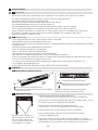
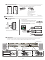
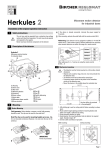
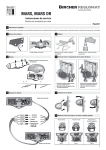
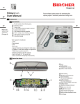
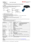
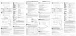
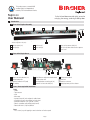
3.3 Selecting the Detection Area Depending on the door opening, a right or left sensing location must be selected. The selector can be found on the backside of the optics. Front 4 To change the detection area, slide the plastic selector to position L or R.* Right* Left * Back Position of the detection area L = Left R = Right * *Factory setting Electrical Connection 4.1 Single TopScan Sensor Pre-assembled TopScan Self-Assembly - /~ 1 2 3 4 5 6 + /~ common NC NO Test input/ 1 monitoring 1 1. Remove the existing unwired terminal block by pushing it out from the back with a screwdriver if necessary. 2. Attach the pre-wired terminal block to the terminal receptor pins on the sensor unit. Black Red White Brown Green Cable Monitoring available in stationary mode only - 17 - 37 VDC/ Power + 18 - 26 VAC COM NC NO Blue 1 4.2 Safety signal Monitoring 1 Monitoring available in stationary mode only TopScan System An additional TopScan mounted on the opposite side of the door panel can be connected through the extension connector (terminals 7–12). Wire colors refer to the pre-installed 6-wire cable provided with TopScan assemblies. Pre-installed 6-wire cable Drill hole through aluminum rails & door for cable feed DOOR OPERATOR Pre-installed 6-wire cable 2 wiring changes to be made Power 17-30 VDC/ 18-28 VAC + COM Approach side safety signal NO (NC) White Green Swing side safety signal Blue Brown COM NO (NC) Pre-installed 6-wire cable from other door face Black Red Cable ! BROWN - re-routed from 4 12 11 10 ! BLUE - re-routed from 6 9 8 7 Page 3 1 2 3 4 5 6 BLACK - power - /~ RED - power + /~ WHITE - common GREEN - sensor signal GREEN - sensor signal 12 11 WHITE - sensor signal 10 9 RED - power + /~ 8 BLACK - power - /~ 7 1 2 3 4 5 6