1
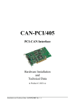
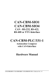
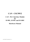
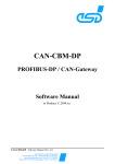
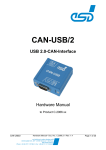
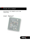
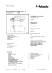
CAN-CBM-BRIDGE/2 Intelligent CAN-Bridge Hardware Manual CAN-CBM-BRIDGE/2 Hardware Rev. 1.2 Document file: I:\texte\Doku\MANUALS\CAN\CBM\Bridge-2\Bridge-2_12.en9 Date of print: 02.08.2003 PCB versions: Rev. 1.1 Changes in the chapters The changes in the manual listed below affect changes in the hardware as well as changes in the description of facts only. Chapter Changes versus previous version 3.2 Notes about mask command added. 4.1 Description of adapter cable ‘combicon-DSUB9’ added. Technical details are subject to change without further notice. CAN-CBM-BRIDGE/2 Hardware Rev. 1.2 NOTE The information in this document has been carefully checked and is believed to be entirely reliable. esd makes no warranty of any kind with regard to the material in this document, and assumes no responsibility for any errors that may appear in this document. esd reserves the right to make changes without notice to this, or any of its products, to improve reliability, performance or design. esd assumes no responsibility for the use of any circuitry other than circuitry which is part of a product of esd gmbh. esd does not convey to the purchaser of the product described herein any license under the patent rights of esd gmbh nor the rights of others. esd electronic system design gmbh Vahrenwalder Str. 207 30165 Hannover Germany Phone: Fax: E-mail: Internet: +49-511-372 98-0 +49-511-372 98-68 [email protected] www.esd-electronics.com USA / Canada: esd electronics Inc. 12 Elm Street Hatfield, MA 01038-0048 USA Phone: Fax: E-mail: Internet: +1-800-732-8006 +1-800-732-8093 [email protected] www.esd-electronics.us CAN-CBM-BRIDGE/2 Hardware Rev. 1.2 Contents Page 1. Overview . . . . . . . . . . . . . . . . . . . . . . . . . . . . . . . . . . . . . . . . . . . . . . . . . . . . . . . . . . . . . . . . . . . . 1.1 Module Description . . . . . . . . . . . . . . . . . . . . . . . . . . . . . . . . . . . . . . . . . . . . . . . . . . . . . 1.2 Front View with Connectors and Coding Switches . . . . . . . . . . . . . . . . . . . . . . . . . . . . . 1.3 Summary of Technical Data . . . . . . . . . . . . . . . . . . . . . . . . . . . . . . . . . . . . . . . . . . . . . . 1.3.1 General Technical Data . . . . . . . . . . . . . . . . . . . . . . . . . . . . . . . . . . . . . . . . . . 1.3.2 Microcontroller Unit . . . . . . . . . . . . . . . . . . . . . . . . . . . . . . . . . . . . . . . . . . . . . 1.3.3 CAN Interface . . . . . . . . . . . . . . . . . . . . . . . . . . . . . . . . . . . . . . . . . . . . . . . . . . 1.3.4 Serial Interface . . . . . . . . . . . . . . . . . . . . . . . . . . . . . . . . . . . . . . . . . . . . . . . . . 1.3.5 Software . . . . . . . . . . . . . . . . . . . . . . . . . . . . . . . . . . . . . . . . . . . . . . . . . . . . . . 1.4 Order Information . . . . . . . . . . . . . . . . . . . . . . . . . . . . . . . . . . . . . . . . . . . . . . . . . . . . . . 3 3 4 5 5 5 6 6 7 8 2. Description of Units . . . . . . . . . . . . . . . . . . . . . . . . . . . . . . . . . . . . . . . . . . . . . . . . . . . . . . . . . . . 9 2.1 CAN Unit Interface Circuit . . . . . . . . . . . . . . . . . . . . . . . . . . . . . . . . . . . . . . . . . . . . . . . 9 2.1.1 Interface circuit . . . . . . . . . . . . . . . . . . . . . . . . . . . . . . . . . . . . . . . . . . . . . . . . . 9 2.2 Serial Interface . . . . . . . . . . . . . . . . . . . . . . . . . . . . . . . . . . . . . . . . . . . . . . . . . . . . . . . . 10 2.2.1 Default Setting of CAN-CBM-Bridge/2 Module . . . . . . . . . . . . . . . . . . . . . . 10 2.2.2 Configuration . . . . . . . . . . . . . . . . . . . . . . . . . . . . . . . . . . . . . . . . . . . . . . . . . 10 2.2.3 Connecting the Serial Interfaces . . . . . . . . . . . . . . . . . . . . . . . . . . . . . . . . . . . 10 2.3 Function of Coding Switches . . . . . . . . . . . . . . . . . . . . . . . . . . . . . . . . . . . . . . . . . . . . . 11 2.4 LED Display . . . . . . . . . . . . . . . . . . . . . . . . . . . . . . . . . . . . . . . . . . . . . . . . . . . . . . . . . 12 3. Configuration of the CAN-CBM-Bridge/2 . . . . . . . . . . . . . . . . . . . . . . . . . . . . . . . . . . . . . . . 3.1 Serial Interface and Coding Switches . . . . . . . . . . . . . . . . . . . . . . . . . . . . . . . . . . . . . . 3.1.1 Commands . . . . . . . . . . . . . . . . . . . . . . . . . . . . . . . . . . . . . . . . . . . . . . . . . . . 3.1.2 Change Existing Configurations . . . . . . . . . . . . . . . . . . . . . . . . . . . . . . . . . . . 13 13 13 18 4. Connector Assignments . . . . . . . . . . . . . . . . . . . . . . . . . . . . . . . . . . . . . . . . . . . . . . . . . . . . . . . 4.1 CAN Bus (X200/X250, Combicon-Style) . . . . . . . . . . . . . . . . . . . . . . . . . . . . . . . . . . . 4.2 RS-232 Interface (X100, 9-pin DSUB male) . . . . . . . . . . . . . . . . . . . . . . . . . . . . . . . . 4.3 Access line for the serial Interface . . . . . . . . . . . . . . . . . . . . . . . . . . . . . . . . . . . . . . . . . 4.4 Power Supply (X101, UEGM) . . . . . . . . . . . . . . . . . . . . . . . . . . . . . . . . . . . . . . . . . . . . 19 19 20 21 22 5. Correctly Wiring Electrically Insulated CAN Networks . . . . . . . . . . . . . . . . . . . . . . . . . . . . 23 CAN-CBM-BRIDGE/2 Hardware Rev. 1.2 1 This page is intentionally left blank. 2 CAN-CBM-BRIDGE/2 Hardware Rev. 1.2 Overview i 1. Overview 1.1 Module Description C A N B U S electrical isolation Physical CAN Layer MSTB2,5/5-5,08 CAN Coding Switches +5 V= DC/DC Converter 3-pole UEGM Connector +5 V= Microcontroller MB90F543 Power Supply 24 V(DC) Serial Interface RS-232 DSUB9 Connector +5 V= DC/DCWandler C A N B U S +5 V= MSTB2,5/5-5,08 Physical CAN Layer CAN Serial EEPROM electrical isolation Fig. 1.1: Block circuit diagram of CAN-CBM-Bridge/2 module The module CAN-CBM-BRIDGE can connect two independent CAN nets. The nets can be operated with different bit rates. The module works with a MB90F453 microcontroller which buffers CAN data into a local SRAM. The firmware is contained in the flash. Parameters are stored in a serial EEPROM. The ISO 11898-compliant CAN interfaces allow a maximum data transfer rate of 1 Mbit/s each. The CAN interfaces are electrically insulated by optical couplers and DC/DC converters. They are connected via 5-pin screw/plug connectors in Combicon design. For matters of service and development the module features a serial interface. RS-232 is used as physical interface. It is connected via a DSUB9 connector. CAN-CBM-BRIDGE/2 Hardware Rev. 1.2 3 i Overview 1.2 Front View with Connectors and Coding Switches Power Supply LED 142 LED 141 LED 140 CAN-Net 0 Coding Switch SW101 (High) Coding Switch SW100 (Low) Serial Interface Power Supply CAN-Net 1 Fig. 1.2.1: Position of connectors and control devices 4 CAN-CBM-BRIDGE/2 Hardware Rev. 1.2 Overview i 1.3 Summary of Technical Data 1.3.1 General Technical Data permitted voltage range 12 VDC ... 32 VDC Nominal voltage 24 VDC , current (at 24 V, 20 C): typ. 100 mA Power supply X100 X300 Connectors X200 X250 (DSUB9, male) - serial interface (2x3-pin screw connector UEGM) 24 V power supply (Combicon design, 5-pin MSTB2.5/5-5.08) CAN net 0 (Combicon design, 5-pin MSTB2.5/5-5.08) CAN net 1 Temperature range 0...50 C ambient temperature, (-20 C ... +70 C on request) Humidity max. 90%, non-condensing Case dimensions (W x H x D) Width: 20 mm, height: 85 mm, depth: 83 mm (including hatrail mount and jutted out connector DSUB9, without CAN connector) Weight ca. 120 g Table 1.3.1: General data of the CAN-CBM modules 1.3.2 Microcontroller Unit Microcontroller MB90F543 Memory SRAM: intern in MB90F543, 6 kbyte Flash-EPROM: intern in MB90F543, 128 kbyte EEPROM: serial SPI-EEPROM Table 1.3.2: Microcontroller units CAN-CBM-BRIDGE/2 Hardware Rev. 1.2 5 i Overview 1.3.3 CAN Interface Number of CAN interfaces 2x CAN CAN controller MB90F543, CAN 2.0A/B, 11-bit and 29-bit CAN identifier Status display yellow LEDs Electrical insulation of CAN interfaces from other units via optocouplers and DC/DC converters reference voltages 300 VDC/250 VAC Physical layer CAN physical layer in accordance with ISO 11898, transfer rate programmable from 10 Kbit/s to 1 Mbit/s Table 1.3.3: Data of CAN interface 1.3.4 Serial Interface Controller MB90F543 Interface RS-232, only the signals RxD, TxD and GND are supported Connection 9-pin DSUB connector Table 1.3.4: Data of serial interface 6 CAN-CBM-BRIDGE/2 Hardware Rev. 1.2 Overview i 1.3.5 Software Configuration via terminal at serial interface Update update option via serial interface CAN bit rate adjustable in 14 steps or bit-timing register of the controller can be programmed directly CAN identifier 11-bit and 29-bit-CAN identifiers (also in combination) Number of CAN-identifier areas which can be masked to link the nets 2 masks per CAN net Number of CAN-identifier links which can be 13 in direction from net 0 to net 1 and set individually 13 in direction from net 1 to net 0 Table 1.3.5: Performance features of the software CAN-CBM-BRIDGE/2 Hardware Rev. 1.2 7 Order Information 1.4 Order Information Type Features Order No. CAN-CBM-BRIDGE/2 CAN-Bridge with 11-bit and 29-bit identifier C.2853.02 CAN-CBM-BRIDGE/2-ME User manual in English 1*) (this manual) C.2853.21 CAN-CBM-BRIDGE/2-ENG Engineering manual in English 2*), Contents: schematic diagrams, PCB top overlay drawing, data sheets of significant components C.2853.25 1*) ... 2*)... If module and manual are ordered together, the manual is free of charge. This manual is liable for costs, please contact our support. Table 1.5.1: Order information 8 CAN-CBM-BRIDGE/2 Hardware Rev. 1.2 Description of Units 2. Description of Units 2.1 CAN Unit Interface Circuit 2.1.1 Interface circuit VCC DC/DC S7U-0505 + + 10µF 5V GND 5V - +5V VC05D150 CAN_GND - 2.2M 2.2nF/250V~ Optical Coupler HCPL7710 10K VCCin IN +5V CAN Transceiver 82C251/ +5V Si9200 VCCout OUT ENABLE CTX0 GND CRX0 to Microcontroller VCC GNDin Optical Coupler HCPL7710 VCCout OUT VDD GNDout +5V TX BUSL RX BUSH R/GND GND GNDout CAN_L CAN_H CAN_GND VCCin IN ENABLE GND X200/ X250 MSTB2.5/5-5,08 GNDin 2 4 1 n.c. 3 n.c. 5 Fig. 2.1.1: CAN interface circuit CAN-CBM-BRIDGE/2 Hardware Rev. 1.2 9 Description of Units 2.2 Serial Interface 2.2.1 Default Setting of CAN-CBM-Bridge/2 Module Bitrate: Data bits: Parity: Stop bit: Handshake: 9600 Baud 8 no 1 XON/XOFF 2.2.2 Configuration The serial interface is controlled by microcontroller MB90F543. The bitrate is 96 000 Baud. Set the user’s terminal / PC to this value. The bitrate can not be changed at the CAN-CBM-Bridge/2 module. 2.2.3 Connecting the Serial Interfaces Below, the wiring of the serial interface is shown. The figure is used to explain the short terms of the signals as used in the chapter Connector Assignments. The signal description is given exemplary for the connection of the CAN-CBM-BRIDGE/2 to a PC. Hint: For the connection of the CAN-CBM-Bridge/2 module to the RS-232 interface of the PCs a nullmodem is necessary (if not already considered by the configuration of the serial lines). CAN-CBM-BRIDGE/2 PC (Terminal, DEE) TxD RxD GND local signalterms (Modem, DÜE) 3 TxD 3 2 RxD 2 5 GND 5 pin numbers of the 9-pole DSUB connector of the CAN-CBM-BRIDGE/2 pin number of the des 9-pole DSUB connector of the PC Fig.2.2: Connection diagram for RS-232 operation 10 CAN-CBM-BRIDGE/2 Hardware Rev. 1.2 Description of Units 2.3 Function of Coding Switches The configuration of the module can be changed via the coding switches. Standard operation: ‘Individual Configuration’: Usually customers configure the CAN-CBM-BRIDGE/2 themselves (see chapter ‘Configuration of the CAN-CBM-BRIDGE/2’, from page 13). For this both coding switches have to be set to ‘0’ when the module is switched on (power on). During configuration and operation the coding switches are not evaluated, therefore it is recommendable to leave them set to ‘0’ at all times. Attention: When switching on the power both coding switches must be set to ‘0’! Settings unequal ‘0’ are only permissible to select customized configurations. Special case ‘Customized Configuration’: By means of the coding switches programmed configurations can be selected. These customized configurations are selected via coding switch positions unequal ‘0’. They can, for example, contain set assignments of CAN-identifiers of both networks. Should you require a lot of CANCBM-BRIDGE/2 modules with the same configuration for an application, feel free to contact our support team. We would be pleased to make you an offer for an individual solution. Coding switch Function Default setting at delivery SW101 (High) Setting of customized configurations ‘0’ SW100 (Low) Setting of customized configurations ‘0’ Table 2.3.1: Function of coding switches CAN-CBM-BRIDGE/2 Hardware Rev. 1.2 11 Description of Units 2.4 LED Display In fault-free status the green as well as both yellow LEDs shine continuously. In case of an error in one of the two CAN-networks the according LED starts flashing. The upper LED 142 (see front view on page 4) shows errors in CAN-network 0 and the middle LED 141 errors in CAN-network 1. LED Colour Function LED 142 yellow status CAN 0 LED 141 yellow status CAN 1 LED 140 green power Status Meaning off no power supply or CPU is not working permanently shining CAN-status OK flashing CAN-error (such as bus off) off power supply ‘off’ shining power supply ‘on’ Table 2.4.1: LED status 12 CAN-CBM-BRIDGE/2 Hardware Rev. 1.2 Configuration 3. Configuration of the CAN-CBM-Bridge/2 This Chapter describes the procedure for the configuration of the CAN-CBM-Bridge/2 which can easily be done e.g. by means of the program ‘Hyperterminal’ of Windows. 3.1 Serial Interface and Coding Switches The serial interface of the PC has to be configured with the values which are described in chapter Default Setting of CAN-CBM-Modules, (page 10). Attention: At the module CAN-CBM-Bridge/2 both coding switches has to be set to ‘0’ at power on! Settings unequal ‘0’ are only permitted for ‘Customized Configuation’ (see page 11). 3.1.1 Commands After the power supply has been switched on the CAN-CBM-module wakes up in the hyperterminal and puts out a message. Now you can enter the commands directly and acknowledge with >Enter<. COMMANDS: R Command R shows the current configuration of the module. In the example below the module is still in default setting. The following message will be displayed: input: R >Enter< output: B0 : 6 B1 : 6 Both CAN nets have got a default bit rate of 125 kbit/s, this corresponds to a HexIndex of 6 (see Table 3.2.1), when leaving the manufacturer. CAN-CBM-BRIDGE/2 Hardware Rev. 1.2 13 Configuration Bn:HexIndex By means of the command Bn: you can configure the desired bit rate of the CAN net with net number n, with: n= 0 for net 0 n= 1 for net 1 If values between 0 hex to F hex are specified for HexIndex, the bit rate is configured according to the following table: HexIndex Bit rate [kbit/s] HexIndex Bit rate [kbit/s] 0 1000 8 66.6 1 666.6 9 50 2 500 A 33.3 3 333.3 B 20 4 250 C 12.5 5 166 D 10 6 125 E reserved 7 100 F reserved Table 3.2.1: Index of bit rate In the following example the bit rate of net 1 (n=1) is to be configured to 10 kbit/s. From Table 3.2.1 you get the HexIndex = D. Your input therefore is as follows: input: Bn:8000yyzz B1:D >Enter< Alternatively you can configure the bit-timing register of the MB90F543 component used, directly. In this case the register value for the bit-timing registers BTR0 and BTR1 is specified directly. n: Here is: 0 ,1... net number yy: value for BTR0 zz: value for BTR1 Please refer to the manuals of the controller MB90F543 for the correct way to determine the bit timing and the bit rate from the register values. The manual can e.g. be downloaded from the Fujitsu-Homepage: http://www.fme.gsdc.de/gsdc.htm?products/mb90495g.htm Choose the ‘MB90F540/545G Series Hardware Manual VX-xx’. 14 CAN-CBM-BRIDGE/2 Hardware Rev. 1.2 Configuration I0:ID net 0 I1:ID net 1 This command assigns an identifier of CAN net 1 to an identifier of CAN net 0. The identifier ID net 0, which is received by CAN net 0 is assigned to identifier ID net 1 of CAN net 1. Note: If you want to configure 29-bit CAN identifier (value range bit 28...bit 0), bit 29 has to be configured (20000000 hex corresponding to CANopen!). In the example below the 29-bit identifier 3456789 hex of net 0 is mapped to the 11-bit identifier 543 hex of net 1. Input: I0:23456789 I1:543 >Enter< In the following example the 11-bit identifier ID net 0 = 200 hex is mapped to the 11-bit identifier ID net 1 = 300 hex. Input: I0:200 I1:300 >Enter< I1:ID Net 1 I0:ID Net 0 This command assigns an identifier of CAN net 0 to an identifier of CAN net 1. The identifier ID net 1, which was received by CAN net 1 is transmitted to identifier ID net 0 of CAN net 0. In the following example the 29-bit identifier ID net 1 = 4567893 hex is to be transmitted to the identifier ID net 0 = 205 hex. Input: I1:24567893 I0:205 >Enter< If you configure an identifier which is not between 0 hex and 7FF hex or within the 29-bit range, the assignment is not accepted. At the moment a total of 13 ID assignments are possible for both directions. CAN-CBM-BRIDGE/2 Hardware Rev. 1.2 15 Configuration Mm:n:zzzzzzzzzzzzzzzzzzzzzzzzzzzzzz This command defines masks for 29-bit identifiers. This way all identifiers or particular areas of identifiers can be assigned. m: 0,1... net in which the identifiers are to be received Here is: n: 0,1... net in which the filtered CAN frames are to be transmitted z...z: 0, 1, x.. mask 0: the according bit has to be logically 0 1: the according bit has to be logically 1 x: the status of the according bit does not matter Attention: Please note that the bits are numbered from right to left. The first bit from the left is therefore bit 30! The mask must always have the full length of 30 bits (29 bits + 30th bit to distinguish between 11-bit and 29-bit identifiers). The first bit is the distinction bit, the following bit is the MSB of the CAN identifier, etc. Bit 30 0 1 x Meaning 11-bit identifier 29-bit identifier 11- and 29-bit identifier In the following example only the odd identifiers between 0 hex and FF hex are let through from net 0 to net 1: Input: M0:1:0000000000000000000000xxxxxxx1 >Enter< If more than one mask has been defined for one direction, one identifier has to pass all masks (AND links) in order to be mapped in the other net. At the moment 2 masks are possible for each direction. 16 CAN-CBM-BRIDGE/2 Hardware Rev. 1.2 Configuration The current configuration of the CAN-CBM-Bridge module from the previous examples can be displayed by means of command R. E Input: R >Enter< Output: B0:6 I0:200 I1:300 I0:23456789 I1:543 M0:1:0000000000000000000000xxxxxxx1 B1:D I1:24567893 I0:205 After the configuration has been successfully completed, the configured data is stored in the configuration memory by means of command E. Only after the data has been stored the changes become effective. The CAN-CBM-Bridge module is now in RUN status and meets the desired bridge function. Input: C E >Enter< You can delete a configuration again by means of the command C. The command deletes all identifier assignments and resets the CAN bit rates to the default value of HexIndex 6, that is a bit rate of 125 kbit/s. The configuration memory is also deleted. Input: C >Enter< CAN-CBM-BRIDGE/2 Hardware Rev. 1.2 17 Configuration 3.1.2 Change Existing Configurations It is not possible to modify single parameters of an existing configuration. You have to call the command C (see page 17) to clear all parameters. After that you have to configure the CAN-CBMBridge/2 again with the correct parameters. Do not forget to call the command E to store the configured data to the configuration memory. 18 CAN-CBM-BRIDGE/2 Hardware Rev. 1.2 Connector Assignments 4. Connector Assignments 4.1 CAN Bus (X200/X250, Combicon-Style) Pin Position: 1 2 3 4 5 Pin Assignment: Pin Signal 1 CAN_GNDx 2 CAN_Lx 3 shield 4 CAN_Hx 5 n.c. Signal description: x... CAN_Lx, CAN_Hx... CAN_GND ... Shield... CAN channel number (x = 1, 2) CAN signal lines reference potential of the local CAN physical layer shielding (The shield lines of both CAN channels are linked directly) The 9-pin DSUB connector is assigned in accordance with CiA DS 102. Fig 4.1: Adapter cable 5-pole Combicon to 9-pole DSUB CAN-CBM-BRIDGE/2 Hardware Rev. 1.2 19 Connector Assignments 4.2 RS-232 Interface (X100, 9-pin DSUB male) Pin Position: Pin Assignment: Signal Pin n.c. 6 n.c. 7 n.c. 8 n.c. 9 Signal 1 n.c. 2 RxD (input) 3 TxD (output) 4 n.c. 5 GND 9-pin DSUB male n.c. ... 20 not connected CAN-CBM-BRIDGE/2 Hardware Rev. 1.2 Connector Assignments 4.3 Access line for the serial Interface Below the access line of the serial interface (RS-232) of the CAN-CBM-BRIDGE/2 to a PC is shown. P1 DSUB female 9-pole 5 4 9 3 8 2 7 1 5 6 4 9 P1: 3 8 2 7 1 6 P2 DSUB female 9-pole P2: (PC) (CAN-CBM-Module) 1 1 RxD 2 TxD 3 4 2 RxD 3 TxD 4 GND 5 5 6 6 7 7 8 8 9 9 GND local signal names used at CAN-CBM-Module Fig. 4.3.1: Assignment of Access line CAN-CBM-BRIDGE/2 Hardware Rev. 1.2 21 Connector Assignments 4.4 Power Supply (X101, UEGM) The power is supplied by means of the UEGM screw connectors integrated in the case. They are suitable for lines with a cross section of up to 2.5 mm². The connector assignment is the same on both sides of the case. They can be used alternatively. The middle contact has been designed for +24 V and the two outer contacts for GND. The permitted voltage range is +12 VDC ... +32 VDC Note: It is not permissible to ‚feed through‘ the 24 V power supply, i.e. to use one side as 24 V input and the other side as 24 V output in order to supply further devices! GND +24V GND CAN-ID HIGH CAN-ID LOW 8 0 8 0 SERIAL GND +24V GND Fig 3.1.1: Power supply 22 CAN-CBM-BRIDGE/2 Hardware Rev. 1.2 Connector Assignments This page is intentionally left blank. CAN-CBM-BRIDGE/2 Hardware Rev. 1.2 23 Wiring 5. Correctly Wiring Electrically Isolated CAN Networks Generally all instructions applying for wiring regarding an electromagnetic compatible installation, wiring, cross sections of wires, material to be used, minimum distances, lightning protection, etc. have to be followed. The following general rules for the CAN wiring must be followed: 1. A CAN net must not branch (exception: short dead-end feeders) and has to be terminated by the wave impedance of the wire (generally 120 W ±10%) at both ends (between the signals CAN_L and CAN_H and not at GND)! 2. A CAN data wire requires two twisted wires and a wire to conduct the reference potential (CAN_GND)! For this the shield of the wire should be used! 3. The reference potential CAN_GND has to be connected to the earth potential (PE) at one point. Exactly one connection to earth has to be established! 4. The bit rate has to be adapted to the wire length. 5. Dead-end feeders have to kept as short as possible (l < 0.3 m)! 6. When using double shielded wires the external shield has to be connected to the earth potential (PE) at one point. There must be not more than one connection to earth. 7. A suitable type of wire (wave impedance ca. 120 : ±10%) has to be used and the voltage loss in the wire has to be considered! 8. CAN wires should not be laid directly next to disturbing sources. If this cannot be avoided, double shielded wires are preferable. Wire structure Signal assignment of wire and connection of earthing and terminator CAN wire with connectors DSUB9 connector (female or male) pin designation CAN_L CAN_GND 120 Ohm CAN_H 1 2 3 4 5 6 7 8 9 connector case DSUB9 connector (female or male) pin designation CAN_GND (at wire shield) n.c. CAN_L n.c. n.c. n.c. n.c. n.c. n.c. CAN_H n.c. n.c. n.c. n.c. n.c. n.c. n.c. n.c. = not connected 1 2 3 4 5 6 7 8 9 connector case 120 Ohm Shielded wire with transposed wires earth (PE) Figure: Structure and connection of wire 24 CAN-CBM-BRIDGE/2 Hardware Rev. 1.2 Wiring Cabling for devices which have only one CAN connector per net use T-connector and dead-end feeder (shorter than 0.3 m) (available as accessory) Connecting CAN_GND to Protective Conductor PE CAN-Board e.g. PCI/405, CAN-USB, VME-CAN2, etc. Net 1 PE Terminator with PE Connector CAN_H Female Connector CAN_L Male Connector CAN_GND Male Terminator (Order-no.: C.1302.01) T-Connector Order-no.: C.1311.03 Net 2 Female Terminator (Order-no.: C.1301.01) l < 0,3 m T-Connector C.1311.03 T-Connector C.1311.03 l < 0,3 m CAN-CBMDIO8 CAN-Cable Order-no.: C.1323.03 T-Connector C.1311.03 l < 0,3 m CAN-CBMAI4 CAN-Cable Order-no.: C.1323.03 T-Connector C.1311.03 Terminator l < 0,3 m CAN-CBMCOM1 l < 0,3 m e.g. CAN-SPS Interface CSC595/2 or CAN-PC Board CAN-Cable Order-no.: C.1323.03 Figure: Example for correct wiring (when using single shielded wires) Terminal Resistance use external terminator, because this CAN later be found again more easily! 9-pin DSUB-terminator with male and female contacts and earth terminal are available as accessories Earthing CAN_GND has to be conducted in the CAN wire, because the individual esd modules are electrically isolated from each other! CAN_GND has to be connected to the earth potential (PE) at exactly one point in the net! each CAN user without electrically isolated interface works as an earthing, therefore: do not connect more than one user without potential separation! Earthing CAN e.g. be made at a connector CAN-CBM-BRIDGE/2 Hardware Rev. 1.2 25 Wiring Wire Length Optical couplers are delaying the CAN signals. By using fast optical couplers and testing each board at 1 Mbit/s, however, esd CAN guarantee a reachable length of 37 m at 1 Mbit/s for most esd CAN modules within a closed net without impedance disturbances like e.g. longer deadend feeders. (Exception: CAN-CBM-DIO8, -AI4 and AO4 (these modules work only up to 10 m with 1 Mbit/s)) Bit rate [Kbit/s] 1000 800 666.6 500 333.3 250 166 125 100 66.6 50 33.3 20 12.5 10 Typical values of reachable wire length with esd interface lmax [m] CiA recommendations (07/95) for reachable wire lengths lmin [m] 37 59 80 130 180 270 420 570 710 1000 1400 2000 3600 5400 7300 25 50 100 250 500 650 1000 2500 5000 Table: Reachable wire lengths depending on the bit rate when using esd-CAN interfaces 26 CAN-CBM-BRIDGE/2 Hardware Rev. 1.2 Wiring Examples for CAN Wires Manufacturer Type of wire U.I. LAPP GmbH Schulze-Delitzsch-Straße 25 70565 Stuttgart Germany www.lappkabel.de e.g. UNITRONIC ®-BUS CAN UL/CSA UNITRONIC ®-BUS-FD P CAN UL/CSA ConCab GmbH Äußerer Eichwald 74535 Mainhardt Germany www.concab.de e.g. BUS-PVC-C (1 x 2 x 0,22 mm²) Order No.: 93 022 016 (UL appr.) BUS-Schleppflex-PUR-C (1 x 2 x 0,25 mm²) Order No.: 94 025 016 (UL appr.) SAB Bröckskes GmbH&Co. KG Grefrather Straße 204-212b 41749 Viersen Germany www.sab-brockskes.de e.g. SABIX® CB 620 (1 x 2 x 0,25 mm²) CB 627 (1 x 2 x 0,25 mm²) (UL/CSA approved) (UL/CSA approved) Order No.: 56202251 Order No.: 06272251 (UL appr.) Note: Completely configured CAN wires can be ordered from esd. CAN-CBM-BRIDGE/2 Hardware Rev. 1.2 27 28 CAN-CBM-BRIDGE/2 Hardware Rev. 1.2