1
Twido and Altivar Magelis & OTB FTB System User Guide 33003614.01 [source code] Sep 2006 Contents Application Source Code................................................................................... 4 Typical Applications .......................................................................................... 5 System................................................................................................................ 6 Architecture ..................................................................................................................... 6 Installation ....................................................................................................................... 9 Hardware ..............................................................................................................................................16 Software ...............................................................................................................................................24 Communication ....................................................................................................................................25 Implementation .............................................................................................................. 29 Communication ....................................................................................................................................32 HMI .......................................................................................................................................................38 PLC.......................................................................................................................................................55 Devices.................................................................................................................................................88 Performance .......................................................................................................................................101 Appendix ........................................................................................................ 102 Detailed Component List ............................................................................................. 102 Component Protection Classes................................................................................... 106 Component Features ................................................................................................... 107 Contact ........................................................................................................... 115 Introduction This document is intended to provide a quick introduction to the described System. It is not intended to replace any specific product documentation. On the contrary, it offers additional information to the product documentation, for installing, configuring and starting up the system. A detailed functional description or the specification for a specific user application is not part of this document. Nevertheless, the document outlines some typical applications where the system might be implemented. Twido_Altivar_Magelis_OTB_FTB_EN.doc Schneider Electric 2 Abbreviations Word / Expression AC Advantys Altivar (ATV) CANopen CB CoDeSys ConneXium DC EDS E-OFF, E-STOP Harmony HMI I/O IclA (ICLA) Lexium/Lexium05/LXM Magelis MB - SL Micro NIM PC Phaseo PLC Powersuite Premium Preventa PS1131 (CoDeSys) PS SE Sycon Telefast TesysU Twido TwidoSoft TwidoSuite Unity (Pro) Vijeo Designer VSD WxHxD XBT-L1000 Twido_Altivar_Magelis_OTB_FTB_EN.doc Signification Alternating Current SE product name for a family of I/O modules SE product name for a family of VSDs Name for a communications maschine bus system Circuit Breaker Hardware-independant IEC 61131-3 programming software SE product name for a Family of Transparent Factory devices Direct Current Electronic Data Sheet Emergency Off switch SE product name for a family of switches and indicators Human Machine Interface Input/Output SE product name for a compact drive SE product name for a family of servo-drives SE product name for a family of HMI-Devices SE name for a serial Modbus communications protocol SE product name for a middle range family of PLCs SE product name for a Network Interface Module Personal Computer SE product name for a family of power supplies Programmable Logic Computer An SE software product for configuring ALTIVAR drives SE product name for a middle range family of PLCs SE product name for a family of safety devices SE Product name for PLC programming software with CoDeSys Power Supply Schneider Electric SE product name of a Field bus programming software SE product name for a series of distributed I/O devices SE product name for a decentralised I/O System SE product name of a middle range family of PLCs SE product name for a PLC programming software SE product name for a PLC programming software SE product name for a PLC programming software An SE software product for programming Magelis HMI devices Variable Speed Drive Dimensions : Width, Height and Depth An SE software product for programming Magelis HMI devices Schneider Electric 3 Application Source Code Introduction Examples of the source code and wiring diagrams used to attain the system function as described in this document can be downloaded from our website under this link. The example source code is in the form of configuration, application and import files. Use the appropriate software tool to either open or import the files. Extension AIW CNF CO CSV CTX DCF DIB DOC DOP EDS FEF GSD ISL PB PDF PS2 RTF SPA STU STX TLX TWD VDZ XEF XPR ZM2 Twido_Altivar_Magelis_OTB_FTB_EN.doc File Type Configuration File Configuration File CANopen definitions file Comma Seperated Values, Spreadsheet Device Configuration File Device Independent Bitmap Document file Project File Electronic Data Sheet – Device Definition Export file EDS file (Geraete Stamm Datei) Island file, project file Profibus definitions file Portable Document Format - document Export file Rich Text File - document Schneider Product Archive Project file Project file Project file Project file Project file Export file Project File Project File Schneider Electric Software Tool Required Advantys Sycon Sycon Twidosoft Unity Advantys Sycon Microsoft Word Magelis XBTL Industrial standard PL7 Profibus Advantys Sycon Adobe Acrobat Powersuite export file Microsoft Word TwidoSuite Unity Pro PL7 Twinline control tool TwidoSoft Vijeo Designer Unity Pro TwidoSuite Zeliosoft 4 Typical Applications Introduction Here you will find a list of the typical applications, and their market segments, where this system or subsystem can be applied: Industrial Small automated machine or plant components Remote automation systems used to supplement large and medium-sized machines Buildings/Services Conveyor belt with turntable Irrigation systems for greenhouses Infrastructure Air-conditioning/ventilation for tunnel systems Food & Beverage/Pharmaceuticals Control and monitoring of pumps and valves Application Conveyor belt with turntable Irrigation systems for greenhouses Air-conditioning/ ventilation for tunnel systems Control and monitoring of pumps and valves Twido_Altivar_Magelis_OTB_FTB_EN.doc Description Image These plant components are often connected upstream of a larger packaging or filling plant as feeder system components. Sorting is possible using photo barriers or weight sensors. This application controls irrigation in greenhouses. Temperature, light and humidity sensors permit the correct irrigation of all types of plants. Tunnel systems must be ventilated according to weather and traffic conditions. Smallscale systems can control turbines and valves in ventilation shafts and monitor carbon monoxide levels and air quality. As part of an overall plant or external station in a water supply/drainage system. Pressure sensors, flow meters and level measuring (e.g., inductive measurements) can be used to adjust delivery according to demand. Schneider Electric 5 System Introduction The system chapter describes the architecture, the dimensions, the quantities and different types of components used within this system. Architecture General The control section of this application consists of a Twido PLC, which can be controlled via a connected Magelis HMI panel. The load section is implemented using Altivar 31 VSDs, which are connected to the control system via the CANopen bus system and two TeSys U-line starter-controllers with reversing contactors. The solution illustrated below offers three optional safety packages: a Preventa evaluation unit featuring an emergency-off function that can be accessed via 2 tamper-proof emergency-off buttons, and an evaluation unit of the same type that ensures door safety within the context of this application by using safety limit switches. A Preventa evaluation unit is also used to monitor a light curtain. Four other OTBs are used as digital I/O for the remote locations H2-H3. Four FTBs are used for sensor acquisition in the field. Layout Twido_Altivar_Magelis_OTB_FTB_EN.doc Schneider Electric 6 Components Hardware: Emergency Off Master switch, 3-pole, 20A, 7.5KW (VCF 02GE) Motor fuse protector Multi 9 21107 Altivar ATV31 variable speed drive with CANopen interface Motor starter, TeSysU-line type XALK locking-type emergency-off button with rotary unlocking (tamper-proof) Emergency-off switching devices, Preventa type Phaseo ABL7 RE power supply unit Modular/compact Twido PLC with CANopen module Magelis XBT-G compact color display terminal Advantys OTB and FTB modules for CANopen ZB5 pushbuttons and indicator lamps OSI family sensors (Osiprox, Osiswitch, Osiris) Standard AC motors Software: Quantities of Components TwidoSuite Version 1.0 Advantys Lite Version 1.4 PowerSuite 2.3 Vijeo Designer V4.4 For a complete and detailed list of components, the quantities required and the order numbers, please refer to the components list at the rear of this document. Degree of Protection Not all the components in this configuration are designed to withstand the same environmental conditions. Some components may need additional protection, in the form of housings, depending on the environment in which you intend to use them. For environmental details of the individual components please refer to the list in the appendix of this document and the appropriate user manual. Technical Data Supply voltage Total supply output Drive rated powers Motor brake Connector cross-section Safety category Twido_Altivar_Magelis_OTB_FTB_EN.doc 400 V AC ~ 11 kW 4 x 0.37 kW None 5 x 2.5mm² (L1, L2, L3, N, PE) Cat. 3 (optional) Schneider Electric 7 Safety notice The standard and level of safety you apply to your application is determined by your system design and the overall extent to which your system may be a hazard to people and machinery. As there are no moving mechanical parts in this application example, category 3 (according to EN954-1) has been selected as an optional safety level. Whether or not the above safety category should be applied to your system should be ascertained with a proper risk analysis. This document is not comprehensive for any systems using the given architecture and does not absolve users of their duty to uphold the safety requirements with respect to the equipment used in their systems or of compliance with either national or international safety laws and regulations Dimensions The dimensions of the devices used for H1 (e.g., the PLC, variable speed drive and the power supply) are suitable for installation inside a small control cabinet measuring 800x600x300 mm (WxHxD). In addition, the display and control elements (e.g., start/emergency-off acknowledgment) can be integrated into the control cabinet door along with the Magelis HMI. The Advantys OTB devices for H2 and H3 with their connection components should be installed directly on site in two small cabinet measuring 300x300x250mm (WxHxD). The buttons can be fed through or, with greater depths (300mm), installed inside the cabinet. The Advantys OTB devices combined with the TeSys U units in H4 should be installed in a cabinet measuring 600x600x300mm (WxHxD). In addition, the display and control elements (e.g., start/emergency-off acknowledgment) can be integrated into the control cabinet door. Twido_Altivar_Magelis_OTB_FTB_EN.doc Schneider Electric 8 Installation Introduction This chapter describes the steps required to assemble the hardware and install the software in order to solve the application task concerned. Assembly Twido_Altivar_Magelis_OTB_FTB_EN.doc Schneider Electric 9 Assembly Contd. Note The configuration used for this application is based on the example of a pallet conveyor system with a turntable. The components and I/O points listed below represent a cross-section of the components and signals that are essential for control and display purposes, and a number of optional inputs and outputs that can be used in this application with the architecture described. Twido_Altivar_Magelis_OTB_FTB_EN.doc Schneider Electric 10 Wiring of the Control Inputs and Outputs Twido PLC inputs %I %I %I %I %I %I %I %I %I %I %I %I 0.0 0.1 0.2 0.3 0.4 0.5 0.6 0.7 0.8 0.9 0.10 0.11 Emergency-off Preventa activated Emergency-off switch 1 pressed Emergency-off contactor activated Light curtain activated Light curtain Preventa activated Motor contactors 1-4 controlled Acknowledge button error Start button Stop button Manual mode button Free Free %I %I %I %I %I %I %I %I 2.0 2.1 2.2 2.3 2.4 2.5 2.6 2.7 Limit switch 1 activated Limit switch 2 activated Emergency-off switch 2 pressed Free Belt 1 fuse OK Belt 2 fuse OK Belt 3 fuse OK Turntable fuse OK Twido PLC outputs %Q %Q %Q %Q %Q %Q %Q %Q Twido power supply Com (inputs) -V Com (+) Com 1 Com 2 Com 3 Twido_Altivar_Magelis_OTB_FTB_EN.doc 1.0 (Trans) 1.1 (Trans) 1.2 1.3 1.4 1.5 1.6 1.7 Free Free Signal lamps – green - Running Signal lamps – yellow - Manual mode Signal lamps – red - Fault Button – blue - Running Button – white - Manual mode Button – blue – Acknow. light curtain 0 V DC reference voltage 0 V DC reference voltage +24 V DC +24 V DC +24 V DC +24 V DC Schneider Electric 11 Wiring of OTB1 Advantys OTB inputs Advantys OTB outputs Advantys OTB power supply Wiring of OTB2 Advantys OTB inputs Advantys OTB outputs Advantys OTB power supply Twido_Altivar_Magelis_OTB_FTB_EN.doc %IWC1.8.0:X0 %IWC1.8.0:X1 %IWC1.8.0:X2 %IWC1.8.0:X3 %IWC1.8.0:X4 %IWC1.8.0:X5 %IWC1.8.0:X6 %IWC1.8.0:X7 %IWC1.8.1:X0 %IWC1.8.1:X1 %IWC1.8.1:X2 %IWC1.8.1:X3 %QWC1.8.0:X0 Trans %QWC1.8.0:X1 Trans %QWC1.8.0:X2 %QWC1.8.0:X3 %QWC1.8.0:X4 %QWC1.8.0:X5 %QWC1.8.0:X6 %QWC1.8.0:X7 Com (inputs) -V Com (+) Com 1 Com 2 Com 3 CANopen Reverse belt 1 Stop belt 1 Forward belt 1 Free Free Free Free Free Free Free Free Free Free Free Free Free Free Free Free Free 0 V DC reference voltage 0 V DC reference voltage +24 V DC +24 V DC +24 V DC +24 V DC %IWC1.9.0:X0 %IWC1.9.0:X1 %IWC1.9.0:X2 %IWC1.9.0:X3 %IWC1.9.0:X4 %IWC1.9.0:X5 %IWC1.9.0:X6 %IWC1.9.0:X7 %IWC1.9.1:X0 %IWC1.9.1:X1 %IWC1.9.1:X2 %IWC1.9.1:X3 %QWC1.9.0:X0 Trans %QWC1.9.0:X1 Trans %QWC1.9.0:X2 %QWC1.9.0:X3 %QWC1.9.0:X4 %QWC1.9.0:X5 %QWC1.9.0:X6 %QWC1.9.0:X7 Com (inputs) -V Com (+) Com 1 Com 2 Com 3 CANopen Reverse belt 2 Stop belt 2 Forward belt 2 Reverse belt 3 Stop belt 3 Forward belt 3 free free free free free free free free free free free free free free 0 V DC reference voltage 0 V DC reference voltage +24 V DC +24 V DC +24 V DC +24 V DC Schneider Electric 12 Wiring of OTB3 Advantys OTB inputs Advantys OTB outputs Advantys OTB power supply Wiring of OTB4 Advantys OTB inputs Advantys OTB outputs Advantys OTB power supply Twido_Altivar_Magelis_OTB_FTB_EN.doc %IWC1.10.0:X0 %IWC1.10.0:X1 %IWC1.10.0:X2 %IWC1.10.0:X3 %IWC1.10.0:X4 %IWC1.10.0:X5 %IWC1.10.0:X6 %IWC1.10.0:X7 %IWC1.10.1:X0 %IWC1.10.1:X1 %IWC1.10.1:X2 %IWC1.10.1:X3 %QWC1.10.0:X0 Trans %QWC1.10.0:X1Trans %QWC1.10.0:X2 %QWC1.10.0:X3 %QWC1.10.0:X4 %QWC1.10.0:X5 %QWC1.10.0:X6 %QWC1.10.0:X7 Com (inputs) -V Com (+) Com 1 Com 2 Com 3 CANopen free Reverse belt turntable Stop belt turntable Forwards belt turntable Reverse belt process Stop belt process Forwards belt process Reverse turntable Stop turntable Forwards turntable free free free free free free free free free free 0 V DC reference voltage 0 V DC reference voltage +24 V DC +24 V DC +24 V DC +24 V DC %IWC1.11.0:X0 %IWC1.11.0:X1 %IWC1.11.0:X2 %IWC1.11.0:X3 %IWC1.11.0:X4 %IWC1.11.0:X5 %IWC1.11.0:X6 %IWC1.11.0:X7 %IWC1.11.1:X0 %IWC1.11.1:X1 %IWC1.11.1:X2 %IWC1.11.1:X3 %QWC1.11.0 :X0 Trans %QWC1.11.0 :X1Trans %QWC1.11.0:X2 %QWC1.11.0:X3 %QWC1.11.0:X4 %QWC1.11.0:X5 %QWC1.11.0:X6 %QWC1.11.0:X7 Com (inputs) -V Com (+) Com 1 Com 2 Com 3 CANopen Free Free Free Door safety contactor Door safety Preventa Module Belt Turntable in reverse Belt Turntable running forwards Belt Process in reverse Belt Process running forwards free free free free free Belt Turntable command reverse Belt Turntable command forwards Belt Process command reverse Belt Process command reverse free free 0 V DC reference voltage 0 V DC reference voltage +24 V DC +24 V DC +24 V DC +24 V DC Schneider Electric 13 Wiring of FTB1 Advantys FTB Advantys FTB power supply Wiring of FTB2 Advantys FTB Advantys FTB power supply Twido_Altivar_Magelis_OTB_FTB_EN.doc %IWC1.4.0:X0 %IWC1.4.0:X1 %IWC1.4.0:X2 %IWC1.4.0:X3 %IWC1.4.0:X4 %IWC1.4.0:X5 %IWC1.4.0:X6 %IWC1.4.0:X7 %QWC1.4.0 %QWC1.4.1 CANopen light curtain belt 1 light curtain belt 2 light curtain belt 3 free free free free free free free %IWC1.5.0:X0 %IWC1.5.0:X1 %IWC1.5.0:X2 %IWC1.5.0:X3 %IWC1.5.0:X4 %IWC1.5.0:X5 %IWC1.5.0:X6 %IWC1.5.0:X7 %QWC1.5.0 %QWC1.5.1 CANopen Proximity sensor Proximity sensor Proximity sensor Proximity sensor free free free free frei frei See FTB1 Schneider Electric Pos1 Pos1.2 Pos2 Pos2.2 14 Wiring of FTB3 Advantys FTB Advantys FTB power supply Wiring of FTB4 Advantys FTB Advantys FTB power supply %IWC1.6.0:X0 %IWC1.6.0:X1 %IWC1.6.0:X2 %IWC1.6.0:X3 %IWC1.6.0:X4 %IWC1.6.0:X5 %IWC1.6.0:X6 %IWC1.6.0:X7 %QWC1.6.0 %QWC1.6.1 CANopen Photo barrier belt turntable free free free free free free free frei frei See FTB1 %IWC1.7.0:X0 %IWC1.7.0:X1 %IWC1.7.0:X2 %IWC1.7.0:X3 %IWC1.7.0:X4 %IWC1.7.0:X5 %IWC1.7.0:X6 %IWC1.7.0:X7 %QWC1.7.0 %QWC1.7.1 CANopen Photo barrier belt sequence free free free free free free free free free See FTB1 Wiring of VSD1 ATV31 CANopen Wiring of VSD2 ATV31 CANopen See VSD1 Wiring of VSD3 ATV31 CANopen See VSD1 Wiring of VSD4 ATV31 CANopen See VSD1 Twido_Altivar_Magelis_OTB_FTB_EN.doc Schneider Electric 15 Hardware General The components designed for installation in a control cabinet, i.e., master switch, Twido PLC, Phaseo power supply unit, emergency-off switching device, line circuit breaker, contactors and motor circuit breaker, can be snapped onto a 35 mm DIN rail. The Altivar variable speed drive can also be snapped onto a DIN rail using an adapter, but can also be screwed directly onto the mounting plate without the need for an adapter plate. The emergency-off and door-safety switches, indicator bank as well as the housing for display and acknowledge indicators, are designed for backplane assembly in the field; with the exception of the door-safety switch, all switches can also be installed directly in a control cubicle (e.g., in cubicle door) without their enclosing housings. There are two options for installing XB5 pushbuttons or indicator lamps: These pushbuttons or switches can be installed either in a 22 mm hole, e.g., drilled into the front door of the control cabinet, or in an XALD-type housing suitable for up to 5 pushbuttons or indicator lamps. The XALD pushbutton housing is designed for backplane assembly or direct wall mounting. The individual components must be interconnected in accordance with the detailed circuit diagram in order to ensure they function correctly. Master switch complete VCF02GE Option for Cabinet door Emergency OFF Master Switch VCD0 Twido_Altivar_Magelis_OTB_FTB_EN.doc Schneider Electric 16 EMERGENCY-OFF switch (tamper-proof) XALK174G Option for Cabinet door Emergency OFF Switch (Tamper Proof) XB5AS8445 Contactor TesysD LC1D093BD Contactor TeSys GV2L08 +GV2AE11 (Maintenance Switch) Twido_Altivar_Magelis_OTB_FTB_EN.doc Schneider Electric 17 TeSys U-line module contactor LUB12 + LU2B12BL + LUA1C11 + LUFN11 + LUCA05BL Preventa safety relay XPS AK331144P Indicator Beacon XVB-C Twido_Altivar_Magelis_OTB_FTB_EN.doc Schneider Electric 18 Position switch OsiSwitch XCKD2121P16 Light curtain XUSLTR5A0350 + cable extensions XSZTCR10 XSZTCT10 Safety limit switch with door safety operating lever XCSPL751 Phaseo power supply unit ABL7RE2410 Twido_Altivar_Magelis_OTB_FTB_EN.doc Schneider Electric 19 Twido PLC modular power base TWDLMDA20DRT Twido PLC interface module CANopen master TWDNCO1M Twido DC IN module 8x DC IN TWDDDI8DT Twido_Altivar_Magelis_OTB_FTB_EN.doc Schneider Electric 20 Twido OTB OTB1C0DM9LP CANopen module 12x DC IN/6x DC OUT/2x AC OUT FTB module 8 IN/diagnostic 8 OUT FTB1CN08E08S Light Curtain XUB1APANM12 Proximity sensor XS608B1PAM12 Twido_Altivar_Magelis_OTB_FTB_EN.doc Schneider Electric 21 Cable for photo barriers and proximity sensor XZCP1264L2 Only 1x M12 connector for sensor: other side must be extended with connector XZCC12FDM40B CANopen connector TSX CANKCDF90TP (additional contact for bus analysis) or TSX CANKCDF90T Both incl. terminating resistor for connection to Twido CANopen Master CANopen cable TSXCANCA50 Magelis operator terminal XBTGT1100 Twido_Altivar_Magelis_OTB_FTB_EN.doc Schneider Electric 22 Variable speed drive Altivar ATV31 ATV31H037N4 CANopen TAP VW3CANTAP2 Twido_Altivar_Magelis_OTB_FTB_EN.doc Schneider Electric 23 Software General The software is primarily used for programming the Twido PLC and configuring CANopen communication, as well as for visualization. The TwidoSuite programming tool is used for programming the PLC. The HMI application on the XBT-GT 1100 Magelis display terminal is configured using Vijeo Designer software. Although Altivar 31 variable speed drives can be parameterized via the front panel, the PowerSuite software is a more user-friendly option. As well as providing a convenient means of setting drive parameters, this software also enables data to be saved and archived. These functions are extremely useful as they mean that parameters can be restored rapidly whenever service tasks need to be performed. The software can also help you to optimize the parameters online. The software is supplied with the drive. To use the software packages, your PC must have the appropriate Microsoft Windows operating system installed: Windows 2000 or Windows XP The software tools have the following default install paths: TwidoSuite C:\Program Files\Schneider Electric\TwidoSuite Advantys C:\Program Files\Schneider Electric\Advantys Vijeo Designer C:\Program Files\Schneider Electric\VijeoDesigner PowerSuite ATV31 C:\Program Files\Schneider Electric\PowerSuite Twido_Altivar_Magelis_OTB_FTB_EN.doc Schneider Electric 24 Communication HMI <> Twido A Modbus connection is used to exchange data between the Magelis terminal and the Twido PLC. The XBTZ9780 communication cable shown below is needed to connect these two devices. The software driver required for Modbus communication is already contained in the software packages for the Magelis panel and the Twido. Magelis communication cable XBTZ9780 Twido <> PC A TSXPCX1031 (serial) or TSXPCX3030 (USB) communication cable is used to exchange data between the Twido PLC and the programming PC. An extra driver must be installed for the USB cable. The driver for the serial cable is integrated into the TwidoSoft tool. Ensure that switch position 2 is set on the cable. Port 1 must be set/configured on the control system for point-to-point communication. Twido programming cable TSXPCX1031 (serial) or TSXPCX3030 (USB) Twido_Altivar_Magelis_OTB_FTB_EN.doc Schneider Electric 25 HMI <> PC An XBTGZ915 communications cable is used to exchange data between the HMI XBTGT 1100 and the programming PC. This is contained in the Vijeo Designer software package. XBTG programming cable XBTGZ915 ATV31 <> PC Programming the Altivar is done using the cable VW3A8106 and the Powersuite cable RJ45<>SubD9 (black). ATV31-Programming Cable VW3A8106 Twido_Altivar_Magelis_OTB_FTB_EN.doc Schneider Electric 26 CANopen The data transfer between the individual bus clients can be implemented with either self made or pre-confectioned cable. Below you will find a component description. CANopen Master Module TWDNCO1M The CANopen-InterfaceModule is plugged into the Twido PLC and has a Sub-D-9 CANopen connection CANopen Plug TSXCANKCDF90T Use this plug on the TWDNCO1M. Plug includes a terminal resistor. CANopen-Kabel TSXCANCD50 Flexibles Kabel CANopen-TAP VW3CANTAP2 Connection for 2 drives of type Altivar 31. Configuration port for use with PowerSuite. Terminal resisitor can be selected using the ON /OFF switch. The image shows the resistor set to OFF. CanOpen Branch Cable VW3CANRR1 Connects the TAP to the Altivar 31 with two RJ54 plugs. Twido_Altivar_Magelis_OTB_FTB_EN.doc Schneider Electric 27 Bus Cable CANopen FTXCN3210 Connect the FTB modules in serie starting with the CANopen-Tap VW3CANTDM4. PIN 1 2 3 4 5 Signal Colour Shld V+ Red GND Black CAN_H White CAN_L Blue Power Supply Cable FTXDP2210 the FTB power supply cables are linked in serie from one module to the next. PIN Signal Cable 1 0V 1 2 0V 2 3 PE Green/Yellow 4 +24V DI 3 5 +24V DO 4 Advantys FTB Terminal Resistor CANopen FTXCNTL12 Connect to the last FTBModule in the series on the BUS OUTSocket. Twido_Altivar_Magelis_OTB_FTB_EN.doc Schneider Electric 28 Implementation Introduction The implementation chapter describes all the steps necessary to initialise, to configure, to program and start-up the system to achieve the application functions as listed below. Function This is a simple function which has been selected to illustrate all of the components used in a practical application and to demonstrate their functions.The function can of course be modified to your own requirements. General The conveyor belt system consists of five belts. The packets are delivered via the chute onto the first belt. The first three belts, operating at different speeds, increase the distance between the packets and are controlled by the first three VSDs. The next stage is a short belt on a turntable. The turntable alters the direction of transport by 90°. The packet is finally conveyed via a fifth belt to the exit. Here the packet is passed onto the next section by a robot. Photo barriers are used to isolate the packets so that at any time there is only one packet in a segment/belt. All three belts are controlled by variable speed drives (VSD) to permit differing speeds. Belt 4 only accepts packets from belt 3 in the “Receive” position, during which belt 4 is driven then stopped as soon as the photo barrier is broken. The turntable then moves to the next position, “Release”. As soon as the turntable reaches the “Release” position, the belt is restarted and then runs for a certain time to ensure that the packet has left the belt. The turntable then returns to the “Receive” position. The turntable is controlled by a fourth VSD and monitored by four proximity sensors as position indicators and two limit switches as impact protection devices.. Belt 5 receives the packet in the “Receive” position and conveys it until it has passed the photo barrier. If the photo barrier is then opened, the belt is run as “Empty”. Belts 4 and 5 are both controlled by a TeSys U. The belts are thus run at a constant speed. Manual & Auto There are 3 operation modes: Manual and Automatic and HMI. A pushbutton is provided to change between manual and automatic. It reacts to a rising edge. The individual buttons for motor control are only enabled in manual mode but the buttons in the 4-button housing and the two individual acknowledge buttons are excluded from this precondition. The HMI mode can only be selected and de-selected on the Magelis XBTG device. Twido_Altivar_Magelis_OTB_FTB_EN.doc Schneider Electric 29 Safety devices the Emergency-off buttons switch the power off for the complete plant. This excludes all PLC components and sensors. This is registered and displayed as a fault on the illuminated beacon. As long as the fault is present, the acknowledge button blinks, turning to permanent when the emergency off buttons have been unlocked. When activated, the light curtain isolates all four VSDs from the motors. This is signaled and displayed as a fault on the illuminated beacon. Although an acknowledgement is possible, the acknowledge button for the light curtain assumes that the fault is still active and blinks permanently. The door switch disconnects the two belt motors from the TeSys U units when the door is opened. Although an acknowledgement is possible, the acknowledge button for the door switch assumes that the fault is still active and blinks permanently. All switch-off operations are performed on the hardware itself, only the relevant fault signaling must be performed in the PLC. Push Buttons The buttons as described here and in the assembly model, are housed in an external housing. They could, however, be built into a cabinet door. If you decide on this option, the buttons require a 22mm diameter hole and you do not need to order the separate button housing. The quadruple button housing is for the buttons Start, Stop, Man/Auto und Acknowledge. Start CANopen Master Reset on Slave fault Stop Error reset for ATV31 Devices after CANopen Initialisation. Man/Auto Automatic Mode (white LED off) / Manual Mode (white LED blinks) Acknowledge1 E-OFF button 1 and E_OFF button 2 Acknowledge button 2 Light curtain Acknowledge button 3 Door switch All Preventa modules send Information to the PLC. Manual mode provides 3 control buttons for all belts: Button 1 reverse belt Button 2 stop belt Button 3 belt forwards Illuminated beacon The illuminated beacon displays the various states. It consists of three indicator lamps. The green lamp indicates Run. It is permanently lit when the plant is operating normally. The red lamp indicates a Fault. The lamp flashes for emergency-off/safety violations; for other faults caused by logic- or component-related problems, the light should burn continuously. The yellow lamp indicates Manual or HMI mode. Twido_Altivar_Magelis_OTB_FTB_EN.doc Schneider Electric 30 Plant Example Conveyor belt system CANopen Layout Twido_Altivar_Magelis_OTB_FTB_EN.doc Schneider Electric 31 Communication Introduction This lists the individual points between which data is exchanged via the bus systems (e.g., CANopen, Modbus Plus or TCP/IP) that are not directly linked to digital or analog hardware interfaces. This list Device Links contains: The devices concerned in each case The direction of transfer The symbolic name and The direct bus address on the device concerned. The Modbus and CANopen bus systems are used in this application. The devices below are networked via CANopen: - a Twido PLC, bus address 127 (fixed setting) four Altivar variable speed drives, bus addresses 1..4 four FTBs, bus addresses 5..8 four OTBs, bus addresses 9..12 Only two devices are interconnected via Modbus: - Magelis-Panel XBT-G, bus address 1 Twido PLC, bus address 2 Datalink Drive_1 <> PLC Twido PLC Altivar 31, Drive_1 (CANopen master, #127) (CANopen slave #1) Data direction ATV -> PLC Address Name Index Designation %IWC1.0.0 D_STATUS_DRIVE_1 6041 Drivecom status register %IWC1.0.1 D_CONTROL_DRIVE_1 6044 Control effort %IWC1.0.2 D_IERROR_DRIVE_1 603F Error Code Data direction PLC -> ATV Address Name Index Designation %QWC1.0.0 D_COMMAND_DRIVE_1 6040 Drivecom command register %QWC1.0.1 D_TARGET_DRIVE_1 6042 Target velocity Datalink Drive_2 <> PLC Twido PLC Altivar 31, Drive_2 (CANopen master, #127) (CANopen slave #2) Data direction ATV -> PLC Address Name Index Designation %IWC1.1.0 D_STATUS_DRIVE_2 6041 Drivecom status register %IWC1.1.1 D_CONTROL_DRIVE_2 6044 Control effort %IWC1.1.2 D_IERROR_DRIVE_2 603F Error Code Data direction PLC -> ATV Address Name Index Designation %QWC1.1.0 D_COMMAND_DRIVE_2 6040 Drivecom command register %QWC1.1.1 D_TARGET_DRIVE_2 6042 Target velocity Twido_Altivar_Magelis_OTB_FTB_EN.doc Schneider Electric 32 Datalink Drive_3 <> PLC Twido PLC Altivar 31, Drive_3 (CANopen master, #127) (CANopen slave #3) Data direction ATV -> PLC Address Name Index Designation %IWC1.2.0 D_STATUS_DRIVE_3 6041 Drivecom status register %IWC1.2.1 D_CONTROL_DRIVE_3 6044 Control effort %IWC1.2.2 D_IERROR_DRIVE_3 603F Error Code Data direction PLC -> ATV Address Name Index Designation D_COMMAND_DRIVE_3 %QWC1.2.0 6040 Drivecom command register %QWC1.2.1 D_TARGET_DRIVE_3 6042 Target velocity Datalink Drive_4 <> PLC Twido PLC Altivar 31, Drive_1 (CANopen master, #127) (CANopen slave #4) Data direction ATV -> PLC Address Name Index Designation %IWC1.3.0 D_STATUS_DRIVE_4 6041 Drivecom status register %IWC1.3.1 D_CONTROL_DRIVE_4 6044 Control effort %IWC1.3.2 D_IERROR_DRIVE_4 603F Error Code Data direction PLC -> ATV Address Name Index Designation %QWC1.3.0 D_COMMAND_DRIVE_ 6040 Drivecom command register 4 %QWC1.3.1 D_TARGET_DRIVE_4 6042 Target velocity Datalink FTB1 <> PLC Twido PLC (CANopen master, #127) FTB1 (CANopen slave #5) Data direction FTB -> PLC Address Name Index Designation %IWC1.4.0 FTB_IN_1 6000 Digital Input 8 Bits Data direction PLC -> FTB Address Name Index Designation %QWC1.4.0 Test_FTB1 6200 Write Outputs 1 to 8 Datalink FTB2 <> PLC Twido PLC (CANopen master, #127) FTB2 (CANopen slave #6) Data direction FTB -> PLC Address Name Index Designation %IWC1.5.0 FTB _IN_2 6000 Digital Input 8 Bits Data direction PLC -> FTB Address Name Index Designation %QWC1.5.0 Test_FTB2 6200 Write Outputs 1 to 8 Datalink FTB2 <> PLC Twido PLC (CANopen master, #127) FTB3 (CANopen slave #7) Data direction FTB -> PLC Address Name Index Designation %IWC1.6.0 FTB _IN_3 6000 Digital Input 8 Bits Data direction PLC -> FTB Address Name Index Designation %QWC1.6.0 Test_FTB3 6200 Write Outputs 1 to 8 Twido_Altivar_Magelis_OTB_FTB_EN.doc Schneider Electric 33 Datalink FTB4 <> PLC Twido PLC (CANopen master, #127) FTB4 (CANopen slave #8) Data direction FTB -> PLC Address Name Index Designation %IWC1.7.0 FTB _IN_4 6000 Digital Input 8 Bits Data direction PLC -> FTB Address Name Index Designation %QWC1.7.0 Test_FTB4 6200 Write Outputs 1 to 8 Datalink OTB1 <> PLC Twido PLC (CANopen master, #127) OTB1 (CANopen slave #9) Data direction OTB -> PLC Address Name Index Designation %IWC1.8.0 OTB1 _IN_00_07 6000 Digital Input 0 to 7 %IWC1.8.1 OTB1 _IN_08_11 6000 Digital Input 8 to 11 Data direction PLC -> OTB Address Name Index Designation %QWC1.8.0 OTB1_OUT_00_07 6200 Write Outputs 0 to 7 Datalink OTB2 <> PLC Twido PLC (CANopen master, #127) OTB2 (CANopen slave #10) Data direction OTB -> PLC Address Name Index Designation %IWC1.9.0 OTB2 _IN_00_07 6000 Digital Input 0 to 7 %IWC1.9.1 OTB2 _IN_08_11 6000 Digital Input 8 to 11 Data direction PLC -> OTB Address Name Index Designation %QWC1.9.0 OTB2_OUT_00_07 6200 Write Outputs 0 to 7 Datalink OTB3 <> PLC Twido PLC (CANopen master, #127) OTB3 (CANopen slave #11) Data direction OTB -> PLC Address Name Index Designation %IWC1.10.0 OTB3 _IN_00_07 6000 Digital Input 0 to 7 %IWC1.10.1 OTB3 _IN_08_11 6000 Digital Input 8 to 11 Data direction PLC -> OTB Address Name Index Designation %QWC1.10.0 OTB3_OUT_00_07 6200 Write Outputs 0 to 7 Datalink OTB4 <> PLC Twido PLC (CANopen master, #127) OTB4 (CANopen slave #12) Data direction OTB -> PLC Address Name Index Designation %IWC1.11.0 OTB4 _IN_00_07 6000 Digital Input 0 to 7 %IWC1.11.1 OTB4 _IN_08_11 6000 Digital Input 8 to 11 Data direction PLC -> OTB Address Name Index Designation %QWC1.11.0 OTB4_OUT_00_07 6200 Write Outputs 0 to 7 Twido_Altivar_Magelis_OTB_FTB_EN.doc Schneider Electric 34 Datalink HMI -> PLC Twido PLC (Modbus #2) HMI Magelis XBT-G (Modbus #1) Data direction HMI -> PLC Address Name Address Designation %M101 M_AUTO %M102 Automatic mode %M106 HMI_resetcanopen %M106 Reset CANopen Master %M107 HMI_resetaltivar %M107 Reset Altivar31 %M121 M_HAND %M122 Manual mode %M131 M_HMI %M131 HMI mode %M200 Mhmi_D1_FWD %M200 Drive 1 Forward HMI %M201 Mhmi_D1_REV %M201 Drive 1 Reverse HMI %M202 Mhmi_D1_STOP %M202 Drive 1 Stop HMI %M205 Mhmi_D2_FWD %M205 Drive 2 Forward HMI %M206 Mhmi_D2_REV %M206 Drive 2 Reverse HMI %M207 Mhmi_D2_STOP %M207 Drive 2 Stop HMI %M210 Mhmi_D3_FWD %M210 Drive 3 Forward HMI %M211 Mhmi_D3_REV %M211 Drive 3 Reverse HMI %M212 Mhmi_D3_STOP %M212 Drive 3 Stop HMI %M215 Mhmi_D4_FWD %M215 Drive 4 Forward HMI %M216 Mhmi_D4_REV %M216 Drive 4 Reverse HMI %M217 Mhmi_D4_STOP %M217 Drive 4 Stop HMI %M220 Mhmi_D5_FWD %M220 Drive 5 Forward HMI %M221 Mhmi_D5_REV %M221 Drive 5 Reverse HMI %M222 Mhmi_D5_STOP %M222 Drive 5 Stop HMI %M225 Mhmi_D6_FWD %M225 Drive 6 Forward HMI %M226 Mhmi_D6_REV %M226 Drive 6 Reverse HMI %M227 Mhmi_D6_STOP %M227 Drive 6 Stop HMI %MW15 Manu_Velo_1 %MW15 Drive 1 Target Value %MW16 Manu_Velo_2 %MW16 Drive 2 Target Value %MW17 Manu_Velo_3 %MW17 Drive 3 Target Value %MW18 Manu_Velo_4 %MW18 Drive 4 Target Value %MW230 CAN_Failure_Slaves %MW17 Failure bit for every Slave %MW232 CAN_Failure_BUS %MW18 Failure bit for the BUS Twido_Altivar_Magelis_OTB_FTB_EN.doc Schneider Electric 35 Datalink PLC -> HMI Twido PLC (Modbus #2) HMI Magelis XBT-G (Modbus #1) Data direction PLC -> HMI Address Name Address Designation %M101 M_auto %M101 Automatic Mode %M102 HMI_estop1 %M102 E-off 1 pressed %M103 HMI_lightcurrtain %M103 Light curtain active %M104 HMI_door %M104 Door Protection Triggered %M105 HMI_estop2 %M105 E-off 2 pressed %M140 M_no_error_drive1 %M140 Drive1 o.k. %M141 M_no_error_drive2 %M141 Drive2 o.k. %M142 M_no_error_drive3 %M140 Drive3 o.k. %M143 M_no_error_drive4 %M140 Drive4 o.k. %M144 M_no_error_drive5 %M140 Drive5 o.k. %M145 M_no_error_drive6 %M140 Drive6 o.k. %MW15 Manu_Velo_1 %MW15 Drive 1 Target Value %MW16 Manu_Velo_2 %MW16 Drive 2 Target Value %MW17 Manu_Velo_3 %MW17 Drive 3 Target Value %MW18 Manu_Velo_4 %MW18 Drive 4 Target Value %MW204 B1Actual %MW204 Drive 1 Actual Value %MW205 B2Actual %MW205 Drive 2 Actual Value %MW206 B3Actual %MW206 Drive 3 Actual Value %MW207 B4Actual %MW207 Drive 4 Actual Value %MW230 CAN_Failure_Slaves %MW230 Failure bit for every Slave %MW232 CAN_Failure_BUS %MW232 Failure bit for the BUS Twido_Altivar_Magelis_OTB_FTB_EN.doc Schneider Electric 36 General Addressing Various hardware addresses, as well as flags and flag words, are used in the PLC example program. To facilitate orientation, an overview of the addresses used appears below in list format. Type Address Comment Digital inputs %Ir.m.x Digital inputs are specified on a hardware basis: r indicates the rack number, m the slot and x the input number. Example: Emergency-off feedback %I0.3.0. Digital outputs %Qr.m.x Digital outputs are specified on a hardware basis: r indicates the rack number, m the slot and x the output number. Example: Indicator lamp for manual mode %Q0.5.1. Analog inputs %IWr.m.c Analog inputs are specified on a hardware basis: r indicates the rack number, m the slot and c the channel number. Example: Emergency-off feedback %IW0.3.0. Analog outputs %QWr.m.c Analog outputs are specified on a hardware basis: r indicates the rack number, m the slot and c the channel number. Example: Emergency-off feedback %QW0.3.0. CANopen inputs %MW0 to %MW31 CANopen inputs are written to flag words; individual bits can be addressed via %MWi.x. Example: 2. ATV status word %MW2 CANopen outputs %MW100 to %MW131 CANopen outputs are read by flag words; individual bits can be addressed via %MWi.x. Example: 3. ATV control word %MW104 Data for Viewer %MW200 to %MW299 Data for Viewer is written to flag words. Individual bits are written via block BIT_TO_WORD. Example: Motor velocity %MW220 Data from Viewer %MW300 to %MW399 Data from Viewer is read by flag words. Individual bits are extracted via block WORD_TO_BIT. Example: Motor velocity %MW220 CANopen status %CHr.m.c Status data for CANopen is read via data structure T_COM_CPP110 (IODDT). Channel address: r indicates the rack number, m the slot and c the channel number. Example: CANopen status %CH0.1.1 Twido_Altivar_Magelis_OTB_FTB_EN.doc Schneider Electric 37 HMI Introduction This application features a Magelis XBT-GT1100 HMI device, which is connected to the PLC via Modbus protocol. Vijeo Designer software is used to program and configure the terminal. The following pages describe how to create and upload a program. Proceed as follows to integrate the HMI: Preconditions Create a New Project Install the Correct Driver Configure the Programming Connection Configure the driver Linking Variables Create a Variable Import Project Creating Screens – examples Build the Project Download the Project In order to work with Vijeo Designer you must first: Install Vijeo-Designer V4.4 on your PC. chaeck that the Magelis terminal is connected to a power supply and turned on Connect the Magelis terminal to the PC using the data cable XBTZG925 (USB). Vijeo Designer Layout 1 The Vijeo Designer environment consists of the following elements: 1 - Navigator 2 - Info display 3 - Inspector 4 - Data list 5 - Feedback zone 6 - Toolbox Twido_Altivar_Magelis_OTB_FTB_EN.doc Schneider Electric 38 Create a new Project 1 Start up Vijeo Designer and select Create new Project. You will be automatically guided through the subsequent steps. continue with Next>. 2 Now enter the project name for the application, e.g., “DCO Example”. A more detailed description can be added in the Description or Comment box. No accented characters or umlauts (ö, ü, ä, etc.) are permitted. Continue with Next>. 3 Select the target device to be used. Your target name can be any name you wish. Target Name: Exampleproject Target Type: XBT–GT1000 Series XBTG Model: XBT-GT1100 Continue with Next> Twido_Altivar_Magelis_OTB_FTB_EN.doc Schneider Electric 39 4 The selected device has no Ethernet port, so you can go to the next screen using Next>. 5 In order to be able to exchange data with the PLC, the Magelis terminal requires a communication driver. In the Create New Project dialog, select: Add to go to the New Driver dialog. Install the correct driver 6 In the New Driver dialog select: Schneider Electric Industries SAS in the manufacturer‘s list. Now transfer the Modbus (RTU) driver to the Equipment list as Modbus Equipment for communication with the Twido PLC. Confirm the settings with OK. Twido_Altivar_Magelis_OTB_FTB_EN.doc Schneider Electric 40 7 Once you have added the driver, exit the driver configuration process with Finish. 8 Vijeo Designer now returns you to its work top, with an empty display and the project navigator A single mouseclick on Target1 in the navigator lists the properties of target1 in properties inspector (or if the properties inspector is closed, a right mouseclick on Target1 and selecting Properties in the pop-up menu, opens up the properties inspector) Configure the Programming Connection 1 First check the setup for the USB programming cable XBTZG925. Check the properties of the project and in particular the properties of the COM port. As default it is set to serial and COM1. As we are using a USB cable the connection must be changed. Twido_Altivar_Magelis_OTB_FTB_EN.doc Schneider Electric 41 2 First check in the Windows Device Manager which COM port is used for the USB connection. Here COM4 is used. 3 In Vijeo Designer select the COM to match the Windows setup, in this case COM4, and input it as the COM port. Leave the connection type as it is, Serial. Configure the driver 1 For the communications to work you must set up the parameters in the Modbus RTU-Driver. For this, right mouseclick on ModbusRTU01 in the Navigator and select Configuration... Twido_Altivar_Magelis_OTB_FTB_EN.doc Schneider Electric 42 2 In the Driver Configuration dialog, input: - 19200 Baud - 8 Data bits - 1 Stop bit - No Parity Note: The configuration must match the port definition on the Twido. Exit the dialog with OK. 3 In the Navigator you can rename the configuration to PLC with a right mouseclick on the name and selecting Rename. 4 Rightmouse click on PLC to go to the device configuration. In this configuration the HMI is slave, the PLC is master. 5 In the Equipment Configuration dialog set the Slave Equipment Address to 2. and set the checkbox for IEC61131 Syntax you can leave the other inputs at their default values. Exit with OK. Twido_Altivar_Magelis_OTB_FTB_EN.doc Schneider Electric 43 6 Linking Variables 1 Acknowledge the confirmation for the IEC61131 Syntax with YES. As the variables have already been input in TwidoSuite (or some other Schneider product) . Vijeo-Designer offers an option to link up to these variables. Select the Variables tab in the the Navigator. Right mouse click on the project name (here TARGET1) and select Link Variables… in the pop-up menu 2 In the Link Variables window give the path to the file, the type of file and the Equipment type (here as named above PLC) Select the file and click on Open. Twido_Altivar_Magelis_OTB_FTB_EN.doc Schneider Electric 44 3 In this example the path was set to the TwidoSoft directory, the file type set to TwidoSoft and the Equipment set to PLC. Then a Twido file (*.twd) was selected and opened. 4 Once the file was successfully opened you will be offered a selection list of the available variables Twido_Altivar_Magelis_OTB_FTB_EN.doc Schneider Electric 45 5 Mark the variables you wish to link to and click on Add. 6 Linked variables are now deactivated with grey text. If you have finished linking the variables you require, exit the dialog with a click on Close. Twido_Altivar_Magelis_OTB_FTB_EN.doc Schneider Electric 46 7 Creating a variable 1 All variables can now be viewed in the navigator on the Variables tab. To create variables, click on the Tab Variable in the navigator. A right mouse click on Target1 opens up the pop-up menu Click on : New Variable -> New… followed by the datatype required to go to variable definition dialog. Twido_Altivar_Magelis_OTB_FTB_EN.doc Schneider Electric 47 2 To create a variable you must input a: Variable name Data type Data Source (External) Address in the PLC In the variable properties dialog you can enter the name and a description for the variable Important here is what device delivers the value if it comes from an external system. If this is the case you must enter a ScanGroup and a Device Address. The device address is not the hardware address. It is the memory address in the device that delivers the value. To select a device address click on the button at the right end of the list box. Device Address: 3 Here you can address bits (%M..), memory words (%MW..) in the PLC. clicking on the Device Address opens up a dialog for the input of the address. PLC internal formats such as counters muss first be transferred to memory words before the Magelis can display them. Integers and Reals : 30001 + i and 40001 + I Discretes: 00001 + 10001 + 30001 + 40001 + i i i, i, and and j and j where „i“ represents the bit number or word number i.e. you address them with the appropriate offset. Twido_Altivar_Magelis_OTB_FTB_EN.doc Schneider Electric 48 4 Examples: PLC %M106 HMI 00001 + 106 => 00107 PLC %MW207 HMI 40001 + 207 => 40208 PLC %MW100 Bit5 HMI 40001 + 100, 5 40101,05 The image shows the variable Test with its attributes listed in the Property Inspector. Import Project 1 To import a project select the Vijeo-Manager tab in the Navigator. Right mouse click on Vijeo-Manager in the tab window opens a pop-up menu. select Import Project.. If the function is de-activated (greyed) close any open projects first and re-try. Twido_Altivar_Magelis_OTB_FTB_EN.doc Schneider Electric 49 2 Enter the path to search in, the file type (*.VDZ) and select a project file from the list offered. Import the project by clicking on Open. Creating Screens Examples 3 When the import is finished, acknowledge with OK. 4 In the Navigator you can now see the project listed. Double click on it to open it. 1 Example: Insert Text Select the text tool in the tool bar. The toolbar displays the toolbox with tools for editing the display. Twido_Altivar_Magelis_OTB_FTB_EN.doc Schneider Electric 50 2 Example: Create Text With the text tool, position the text box on the display. You can adjust its size by „pulling“ on the box or by giving a value in the text editor dialog. Double click on the text box to open up the text editor dialog you can input the text to be displayed and define its size, font, etc. 3 After inputting the text you can define/change the text characteristics in the Property Inspector Twido_Altivar_Magelis_OTB_FTB_EN.doc Schneider Electric 51 4 A right mouse click on the text object in the display leads to the animation. This is the same animation as seen in the property inspector (see image above) but in another format. Both formats contain the same attributes. 5 Animation Properties: Colour Position Value Visibility For the variable used to animate this object, you can either manually input the variable or click on the lightbulb icon to browse the variable list and select a variable. If you input an unknown variable it is shown in red – the variable has yet to be defined Once activated variables can be selected and their display format defined. If the value requires further processing before use, such as trigonomic functions, you can select these via the calculator icon. Twido_Altivar_Magelis_OTB_FTB_EN.doc Schneider Electric 52 Build the project 6 Text and Graphics examples. 7 This picture shows one the finished configuration screens with some animations and buttons 1 Before you download the project to the Magelis you must validate it. With Validate All you can analyse your project. The Feedback Zone shows you the results of the analysis. You can invoke the project analysis using Build All too. Twido_Altivar_Magelis_OTB_FTB_EN.doc Schneider Electric 53 Download the Project 1 Before you can download the project you must build the project (see the section above) Downloading the project to the Magelis (HMI): Select the project in the Navigator. Use Build->Download All to transfer the project to the HMI device. The transfer is done using the configured protocol (modbus in this case). The download process is indicated with a progress bar. Twido_Altivar_Magelis_OTB_FTB_EN.doc Schneider Electric 54 PLC Introduction The PLC chapter describes how to initialize, parameterize and load the program to the PLC in order to implement the functional description described above. The PLC program is created using TwidoSuite. Pre-conditions Before carrying out the steps described below, you must ensure the following: Starting Twidosuite 1 The TwidoSuite programming tool is installed on your PC The TwidoSuite example project is available The Twido PLC is switched on and supplied with power The PLC is connected to the PC with programming cable (TSXPCX1031) To start work with Twidosuite, click on: Programming Mode Use the language selection buttons to set the language for this session. 2 The start up screen for the main menu is displayed. With Create a new project you can start a new project. Twido_Altivar_Magelis_OTB_FTB_EN.doc Schneider Electric 55 Create a new Project 1 Once Create a new Project is selected, enter a Project name and select the Directory path to save it. You can enter Project Information if required but it is not mandatory. Confirm with Create. Select the Hardware 1 Now go to Describe to configure the hardware. 2 In the configuration Workspace you will see a Twido PLC. In the Catalog on the RHS you can select the hardware/modules you wish to configure The Workspace offers you graphical documentation. Twido_Altivar_Magelis_OTB_FTB_EN.doc Schneider Electric 56 3 In the Catalog, first select the correct type of Twido TWDLMDA20DRT. 4 Use Drag&Drop to drag the selection to the graphical image of the Twido. The grahical image will change to green. Drop the selected Twido while the mouse icon is in the green field. Twido_Altivar_Magelis_OTB_FTB_EN.doc Schneider Electric 57 5 As next module select the CANopen Master TWDNCO1M. Use Drag&Drop to place it to the right of the Twido PLC in the graphical image. 6 Now add the extra digital inputs module TWDDDI18DT Again, using drag&drop place it next to the CANopen Master. Twido_Altivar_Magelis_OTB_FTB_EN.doc Schneider Electric 58 7 Now add the Magelis Terminal XBTGT1100 For this add the general Magelis Modbus element to the configuration. 8 The Workspace now shows a graphic display of the configured modules/devices. The connection HMI/PLC, via the Modbus interface, has still to be done. 9 To confgure the HMI connection, move the mouse icon over the HMI until the mouse icon changes to a screwdriver. Now a doubleclick opens up the configuration dialog. Give the device a Name and check that the default Protocol Modbus at Address 1 is offered. Confirm with OK. Twido_Altivar_Magelis_OTB_FTB_EN.doc Schneider Electric 59 10 Name and Modbus address now appear in the graphic display next to the HMI device. 11 Now do the same for the PLC modbus interface. Position the mouse icon on the modbus interface of the PLC. When the mouse icon changes to a screwdriver, doubleclick to open up the configuration dialog. Change the Protocol type to Modbus and set the Address to 2. Confirm with OK. 12 Now connect the two devices in the graphics display by linking the white crosses that reperesent the linking points. To do this click on the white cross of one device and then the next so that the link is displayed. 13 After linking the devices you can give the network a name and set the baud rate by double clicking on the connecting line or the network box. In this case we use the default values. Twido_Altivar_Magelis_OTB_FTB_EN.doc Schneider Electric 60 Hardware Configuration 1 For the hardware configuration select the main menu Program. 2 The screen shows the PLC rack. Note the menus on the RHS and bottom of the display area. Menus on the RHS are sub-menus to the main menu along the top. Twido SPS 1 You can now configure all the I/O variables for the PLC. To name the variables click on the Symbol column for a particular I/O and input the new name. 2 Spaces and special characters are not allowed in symbol names. If the variable is already in use in the program, the check box to the LHS is activated. Twido_Altivar_Magelis_OTB_FTB_EN.doc Schneider Electric 61 3 All symbol names are shown in uppercase. 4 Changes are only made when the Apply button is pressed. If you try to exit the dialog without pressing Apply, you will be reminded. 5 CANopen Master 1 Symbols entered in the configuration are automatically inserted into the variable list. The next step is to configure the CANopen Master. Click on the CANopen module in the graphics image. 2 Click on Configure in the module configuration. Twido_Altivar_Magelis_OTB_FTB_EN.doc Schneider Electric 62 3 The CANopen Configuration Tool appears. 4 If there is no entry in the catalogue for Advantys FTB or Advantys OTB, the SPA files have not been imported. The files are installed with Twidosuite. To import the files, click on the import/export function (arrow icon,top left) to go to the standard Windows Open dialog 5 In the open dialog set the path to the required SPA (Schneider Product Archive) files: File type : *.SPA Path: Twidosuite 6 Once the SPA files are imported they appear in the list under DS-401 . Twido_Altivar_Magelis_OTB_FTB_EN.doc Schneider Electric 63 7 Use the import function to import the EDS Files (Electronic Data Sheet) for the components. Here : FTB_CN08E08SPO.eds (See the example project) 8 The import displays a progress bar. 9 do the same for OTB_1CODM9LP.eds. 10 After a successful import the components are listed as DS-401 I/O Modules. Twido_Altivar_Magelis_OTB_FTB_EN.doc Schneider Electric 64 11 The configuration files for the Altivar 31 drives are already installed. 12 For our example the first four slaves are used by the Altivars. To insert an Altivar as slave, double click on the Altivar entry in the catalogue. Use the arrow icons to move the entries up/down in the list. 13 Slaves 5-8 are the FTB modules. . 14 Ther OTB Modules are Slaves 9-12. 15 Set the baudrate for the CANopen bus to: 500Kbit/s Twido_Altivar_Magelis_OTB_FTB_EN.doc Schneider Electric 65 16 Double click on the Supervision column for each slave and set the supervsion type to heartbeat (the default is normally set to None) 17 In the Mapping tab you can edit the Transmit and Receive PDOs. 18 Note: You do not need to change the PDOs. If you do however, bear in mind that the SDO memory requirement changes. The maximum SDO memory is fixed in the PLC and cannot be exceeded. 19 Use the tab Linking to select the PDOs that are to be transferred. You must do this for both the transmit and receive direction. Twido_Altivar_Magelis_OTB_FTB_EN.doc Schneider Electric 66 20 Under receive AND transmit, doubleclick on the PDO to move it from the slave to the master PDO. Note : all PDOs that are used must be moved. Normally you would move all PDOs. Those not moved are redundant 21 Us the Symbol tab give your I/O variables names. The Altivar 31 variables have standard names but can still be changed. 22 23 Variables without names do not appear in the variable list. For ease of programming it is preferable to give the variables names. To save the configuration click on Apply then exit the dialog with OK. Twido_Altivar_Magelis_OTB_FTB_EN.doc Schneider Electric 67 Digital Input-Modul 27 TwidoSuite now displays a table with all the configured CANopen slaves. 1 Click on the the digital input module in the graphic. The list of Inputs appears for the module. Symbol names can be input and applied. The variables are automatically inserted into the variable list Drive Macros 1 To use the TwidoSuite macros for the Altivar 31, they must first be configured. To do this select: Program-> Configure-> Configure the Data-> Advanced object-> Macros drive Twido_Altivar_Magelis_OTB_FTB_EN.doc Schneider Electric 68 2 For legibility, the macros are given the same number as the slave addresses, i.e. 1 – 4. 3 Select a macro to configure it by activating the check box. Set: Network: CANopen Network Address : 1 4 Reserve the memory words for the function in the entry D_Manager. In the example 30 words are reserved for macro drive 1, from MW30 to MW59, by giving the start address and the number of words required 5 Setting the check box in the Symbols column allows the variables to be included in the variable list. 6 Click Apply to implement the drive configuration. In the example drives 14 are set up with MW30, MW60, MW90 and MW120 Twido_Altivar_Magelis_OTB_FTB_EN.doc Schneider Electric 69 7 Change now to the main menu Describe and you will receive a request to resize the workspace. Acknowledge the message with OK. Resizing Workspace 8 TwidoSuite has increased the workspace and the configured drives and CANopen bus are now shown in the graphics. 1 You can re-position objects in the graphic to save space and for better legibility. Note: if you now print the image for documentation purposes empty fields are printed too. 2 To delete the empty fields, change the workspace format from 3x3 to 1x2. Twido_Altivar_Magelis_OTB_FTB_EN.doc Schneider Electric 70 Variable List 3 The re-sized workspace. 1 In the variable list you can add symbols, give them a memory address and input a comment about them. 2 To add a symbol click on the insert icon. First enter the symbol name. Now you can add the address and a comment. Create an application Program 3 Use the different column headers as sort criteria to sort the table in alphabetical order. 1 Use the Edit Program function to go to the program editor. Starting a new program always begins with LADDER as the programming language. You can only view the program in LIST mode once the first rung has been completed and analysed. Twido_Altivar_Magelis_OTB_FTB_EN.doc Schneider Electric 71 2 Starting with an empty program, add a section. This will create a section with empty rungs. The first rung is marked in red on the LHS to denote that it has logical errors. 3 Click on the top of a rung to rename it. 4 You can also rename the section 5 Clicking on the rung changes its colour to green and indicates the current rung being edited. Clicking on an icon in the toolbar inserts the selected object at the first available place on the rung. So, you can add contacts… ….and outputs, etc. 6 7 To make a logical connection, simply mark the source and pull it to the destination. All possible connecting points are shown in green Twido_Altivar_Magelis_OTB_FTB_EN.doc Schneider Electric 72 8 Once a link has been inserted you can add a contact to form the logical OR. 9 To assign an object to an address or variable, click on the upper half of the object 10 The editor automatically recognises whether a rung is syntactically complete and marks it in yellow. The rung, however,has not yet been analysed. The analyze program button is in the bottom right hand corner. 11 The Analysis is done for all contacts. Twido_Altivar_Magelis_OTB_FTB_EN.doc Schneider Electric 73 12 If the analysis is error free, the yellow band changes to green. You can now change the display mode to LIST if you wish. 13 If erros are found, these are listed at the bottom of the edit field. Click on the arrow icon to enlarge the display. 14 A common error is No Start In Run Was Selected 15 To fix this, select: Program-> Configure-> Configure the behavior In the Configure the Behavior dialog select: Automatic start in Run This is an operation mode that causes the PLC to start up automatically on return of power after a power failure. Twido_Altivar_Magelis_OTB_FTB_EN.doc Schneider Electric 74 Macro Drive 16 After restarting the analysis the error field is empty. 1 To use the macros for the drives, a second rung is added using the add a rung icon. 2 Insert an operation block for the macro. 3 To link the operation block to the macro drive input D_manager 1. D_manager is the macro function to access the drive and the 1 indicates Drive 1. 4 The space between D_manager and the 1 is mandatory. Twido_Altivar_Magelis_OTB_FTB_EN.doc Schneider Electric 75 5 As the macro is already configured, the address field also contains the symbolic macro name D_MANAGER 1. The SHORT seen here must be exchanged for a control variable. You can now repeat this for the other macros: D_CLEAR_ERR D_RUN_FWD D_RUN_REV D_STOP und D_SELECT_SPEED . Save / export the project 1 To save the project select Save current project in the Project menu. In the Save current project window you can select the folder for the save, input the file name and designate the file Format. You can save the file as a normal Project file or as an Archive file. The Archive file has the advantage of being portable and is a single file. Twido_Altivar_Magelis_OTB_FTB_EN.doc Schneider Electric 76 Open a Project 1 To open a project use the Open an existing project function in the Project menu. In the open an existing project window select the medium : disk or Controller Give the file type under Format (for a project file: Project), select the folder and select the file you wish to open. When ready, click on Open to open the project Twido_Altivar_Magelis_OTB_FTB_EN.doc Schneider Electric 77 Import a Project 1 Proceed as for Open a project (above) except for import, the file type is Archive. Connecting to the PLC 1 To connect the PC to the PLC select Program in the main menu, then Debug in the sub-menu to get access to the connect selection. 2 You can now either configure a new connection (see menu at bottom of window) or select a preconfigured connection. To connect click on OK. Twido_Altivar_Magelis_OTB_FTB_EN.doc Schneider Electric 78 Download a Program 3 you will be shown a progress bar while Twidosuite establishes the connection. 1 After succesfully connecting to the Twido, Twidosuite compares the status of the project and the Twido PLC. Now you can either download your project or upload the contents of the PLC. 2 To download the project select: Transfer PC->controller and confirm with OK 3 If the Twido is already running it must be stopped first. Confirm with OK if you wish to proceed. 4 You will be shown a warning that the contents of the PLc are about to be overwritten confirm with OK to continue. 5 The download condition is indicated with a process bar. Twido_Altivar_Magelis_OTB_FTB_EN.doc Schneider Electric 79 6 After a successful download, Twidosuite jumps automatically to the online viewing. 7 A control panel appears in the foreground. Here you can start and stop the PLC. The upper button extends the window, offering more PLC status information 8 If you start the PLC you will be asked to confirm the action If you wish to proceed with the start click on OK. 9 After successfully starting the PLC the RUN LED changes from yellow to green. Twido_Altivar_Magelis_OTB_FTB_EN.doc Schneider Electric 80 10 Here the expanded window with the PLC in run mode. 11 If the online status window is closed, a click in the upper left hand corner of the main window opens it again. 12 The sub-menu Manage animation tables allows acces to animation tables. Twido_Altivar_Magelis_OTB_FTB_EN.doc Schneider Electric 81 13 Use the project browser to navigate through the program sections. Twido_Altivar_Magelis_OTB_FTB_EN.doc Schneider Electric 82 Advantys OTB/FTB Introduction The OTB/FTB chapter describes how to address the Advantys OTB and Advantys FTB devices to fulfill the system functionality as described above. General OTB and FTB addressing are performed in an identical manner on the device using a small screwdriver. Since in our example the OTB and FTB devices operate with a CANopen bus which connects them to the Twido PLC, the addresses lie within the range 1-16. The CANopen bus can normally manage up to 128 slaves, but since a Twido is used for the master PLC in this example, only 16 slaves with addresses 1-16 can be used. Other bus components with higher addresses are neither detected nor addressed. Setting the CANopen Address 1 During the TwidoSoft CANopen configuration process, an address is automatically assigned to the individual CANopen bus components in their order of installation. In our example there are four ATV31 drives on addresses 14, four FTBs on addresses 5-8 and four OTBs on addresses 9-12. We will use OTB4 with address 12 to illustrate how to assign addresses to the components. The individual components are addressed as follows in the software: For the first OTB with CANopen address 9, the input word is read in the form %IWC1.8.0. This means: %IW = input word C = CANbus 1 = CANopen master slot 8 = CANopen address -1 (9-1=8) Twido_Altivar_Magelis_OTB_FTB_EN.doc Schneider Electric 83 OTB 2 The OTB address is set using the rotating switches. The tens range from 0-12 which corresponds to 0-120 in steps of 1/10. The units ranges from 0-9. The baud rate is set using lower switch. 3 Use a small screwdriver to adjust the settings. The slot in the adjuster screw has an arrow at one end to indicate the selected address. 4 The first image shows the OTB cover closed. The second, the three adjuster switches with the OTB cover open. Twido_Altivar_Magelis_OTB_FTB_EN.doc Schneider Electric 84 5 In this example, address 12 is set to automatic baud rate recognition (position 8). With automatic recognition, an attempt is made on initialization to synchronize each baud rate, from the highest value (1Mbps) to the lowest. 6 7 Note: automatic baudrate recognition takes longer than manual input. In the table opposite, the relevant baud rate can be determined from the lower adjuster switch. In the table opposite, the relevant baud rate can be determined for the baud rate switch. In our example, a baud rate of 500 kbps is entered in TwidoSoft. Either 5 for 500 kbps or 8 for automatic must therefore be set on the OTBs. Twido_Altivar_Magelis_OTB_FTB_EN.doc Schneider Electric 85 FTB 1 The FTB is shown here. Point 6 shows the adjuster screws on the FTB. The setting area is protected by an IP67 cover. Before adjusting the settings, the cover must first be removed by loosening the two side screws. 2 In the table opposite, the relevant baud rate can be determined for the baud rate adjuster. In our example, a baud rate of 500 kbps is entered in TwidoSoft. Either 7 for 500 kbps or 0 for automatic must therefore be set on the FTBs. Twido_Altivar_Magelis_OTB_FTB_EN.doc Schneider Electric 86 3 Selector 1 here shows the baud rate setting . Selector 2 shows the “tens” position and selector 3 shows the “units” position. Setting is performed as for the OTB. The table for the baud rates and the adjuster screw positions are also identical. In our example, setting proceeds from left to right: - 4 7 for 500kbits/s baud rate 0 for the tenths position 5-8 for the four addresses of our FTBs Another configuration must be created in the software for the FTB modules. Particular output words must be set for this purpose. The FTBs have M12 connectors on which pin 4 stands for an input signal. Pin 2 can then be used for another sensor (with an inverted signal!) or for an alarm prompt. 5 The graphic opposite shows the configuration necessary for our four FTBs. Flag words are used here for an FTB with CANopen address 6 (corresponding to %QWC1.5.0/1) to simulate modifications to the configuration in Run mode. This configuration can be retransmitted at any time. The FTB is initialized only on reception of a new configuration. Twido_Altivar_Magelis_OTB_FTB_EN.doc Schneider Electric 87 Devices Advantys OTB Introduction The Advantys OTB chapter describes how to add an OTB in TwidoSuite and how to create an EDS file. Preconditions Before carrying out the steps described below, you must ensure the following: Starting Advantys for OTB 1 The TwidoSuite programming tool is installed on your PC The OTB.spa file must already be in the TwidoSuite configuration The Advantys tool is installed on your PC In order to start Advantys from the TwidoSoft program, select Advantys OTB after the SPA files have been loaded. Click on the icon with the hammer&spanner to start the Advantys tool for the OTB 2 In the New Island dialog, assign a name. In our example this is: “OTB_CANopen”. Confirm with OK. Twido_Altivar_Magelis_OTB_FTB_EN.doc Schneider Electric 88 3 A startup screen is then displayed. The middle field is the configuration area in which the OTB and its extension modules are created. All known OTB modules and extensions appear on the right-hand side in the Catalog Browser. 4 Select the CANopen OTB used in our example, OTB 1CO DM9LP 5 The OTB now appears as a graphics picture in the central area. Right-click on the image to open up a pop-up menu and select: Configure module. 6 The window for the OTB 1CO DM9LP module opens and you are shown a general summary on the first page. Twido_Altivar_Magelis_OTB_FTB_EN.doc Schneider Electric 89 7 The Digital Inputs tab allows you to define unused inputs. To do this, assign a Yes to the relevant bit (Input 0 = Bit 0, etc.) in the Mask column. Inputs marked Yes will not now be acquired. In our example, all inputs must be marked No. 8 This is also the case for Digital Outputs. No modifications are required to any of the other tabs. Confirm with OK. 9 To save the configuration and create a portable EDS file, click on the icon with the floppy disk. THe EDS file is saved to the EDS folder of the Advantys software. 10 Now close the Advantys window using the system exit. You are automatically prompted to save the changes. confirm with Yes. 11 The installation/save progress bar appears. Twido_Altivar_Magelis_OTB_FTB_EN.doc Schneider Electric 90 11 Following the configuration process, the CANopen Configuration Tool reappears. The OTB file that you have created now appears in the Advantys OTB (V1.0) entry. Twido_Altivar_Magelis_OTB_FTB_EN.doc Schneider Electric 91 Advantys FTB Introduction The Advantys FTB chapter describes how to configure the procedures required to add an FTB to the TwidoSoft. Preconditions Before carrying out the steps described below, you must ensure the following: Adding an FTB Island to Twidosuite 1 The TwidoSuite programming tool is installed on your PC The FTB.spa file must already be in the TwidoSuite configuration The Advantys tool is installed on your PC In order to start Advantys from the TwidoSoft program, select Advantys FTB after the “*.spa” files have been loaded. Click on the icon with the hammer&spanner to start the Advantys tool for the FTB. 2 In the New Island dialog, assign a name. In our example this is FTB_CANopen. Twido_Altivar_Magelis_OTB_FTB_EN.doc Schneider Electric 92 3 A startup screen is then displayed. The middle field is the configuration area in which the OTB and its extension modules are created. All known OTB modules and extensions appear in the catalog browser on the right hand side. 4 Select the CANopen FTB used in our example FTB1CN08E08SPO 5 The FTB now appears as a graphic image in the central area. Right-click on the image and in the pop-up menu, select Configure module Twido_Altivar_Magelis_OTB_FTB_EN.doc Schneider Electric 93 6 The dialog for the FTB1CN08E08SPO module opens and displays a general summary on the first page. 7 The Digital tab allows you to mask unused inputs. To do this, assign a Yes to the relevant channel in the Mask list. Inputs with a Yes will not be acquired. In our example, all inputs must remain at No. 8 9 In addition, you can determine here whether the eight inputs definable with FTB1CN08E08SPO should be used as inputs or as diagnostics. To save the configuration, simply press the button with the floppy disk icon. Now close the window using the system exit. You are now prompted to save the changes to “FTB_CANopen”. Confirm with Yes and the installation progress bar appears. Twido_Altivar_Magelis_OTB_FTB_EN.doc Schneider Electric 94 10 Following the configuration process, the CANopen Configuration Tool reappears. The FTB file “FTB_CANopen” that you have created now appears in the Advantys FTB (V1.0) directory. Twido_Altivar_Magelis_OTB_FTB_EN.doc Schneider Electric 95 Altivar 31 Introduction The ATV31 Devices chapter describes how to initialize and parameterize the Altivar ATV31 devices in order to fulfill the system functionality described above. PowerSuite software is used to initialize and parameterize the devices. General The ATV31 parameters can also be entered or modified via the front panel. The advantages of using PowerSuite are that you PowerSuite with ATV31 Can save the data on your PC and copy it as you wish Can print out the documentation and Can be assisted in optimizing the parameters online. The Parameters can be configured with the Powersuite configuration software. Here, the configuration was done using Powersuite V2.3 1 After starting Powersuite, select the entry Example- folder 2 Via the menu ActionConnect try to connect to the device. Note: make sure the device is connected with thye proper cable. 3 It will be confirmed that you are trying to connect to a new device. Click on Create to continue. 4 In the New name dialog give the configuration for the device a name. Twido_Altivar_Magelis_OTB_FTB_EN.doc Schneider Electric 96 5 You will see a progress bar as the data is read from the altivar 31 device. 6 When the transfer is complete complete, the device data is displayed. 7 You can view the parameter in list form or ... Twido_Altivar_Magelis_OTB_FTB_EN.doc Schneider Electric 97 8 ... in an input mask which can be viewed via: Adjustments-> Motor control -> Motor Charakteristics 9 Enter the Motor data of the type of motors used. 10 In the entry Communication enter the CANopenAddress (for this application 1 to 4) and select : Baudrate: 500 kbit/s. Twido_Altivar_Magelis_OTB_FTB_EN.doc Schneider Electric 98 11 Save the data.. 12 To transfer the new parameters to an individual device, right mouse click on the entry for the device and select: download in the pop-up menu. 13 Confirm the warning message with OK . Twido_Altivar_Magelis_OTB_FTB_EN.doc Schneider Electric 99 Manual Input using the Altivar Front Panel You can configure the ATV 31 by inputting the parameters using the front panel display and buttons on each Altivar, as follows: 1 The CANopen-Address and Baudrate can be input using the buttons on the front panel of the Altivar. 2 Using the buttons on the front panel, select the sub-menu Communication auszuwählen. 3 In the Communication submenu input the CANopen address in the parameter AdC0. In the example application the adresses for the four controlers are 1 to 4. 4 Also in the Communication sub-menu, in the parameter BdC0, set the baudrate to 500.0 (kBits). 5 Alternatively you can use the PowerSuite software to configure the CANopen addresses and baudrates. 6 To activate the downloaded bus parameters (address and baudrate) you must now switch off the controller (display goes off). On switching back on, the new parameters are ready. Twido_Altivar_Magelis_OTB_FTB_EN.doc Schneider Electric 100 Performance Scan time and cycle time A cycle time of 2 ms was not exceeded with the present configuration including the required application code. The memory utilization of the Twido PLC specified and used in this SMD was 7% for system data and 2% for the logic component. Trials with additional integrated extension modules (a digital I/O module with 16 inputs and 8 relay outputs as well as an analog module with 1 output and 2 inputs, which was used as the I/O level for 2 PID controllers) showed that the cycle time could be increased to a maximum of 6 ms. When using these two additional extension modules, memory usage for system data rose to 22% but, as expected, memory usage of the logic component did not change. Twido_Altivar_Magelis_OTB_FTB_EN.doc Schneider Electric 101 Appendix Detailed Component List Hardware components – Group 1: Master switch Item Qty Description Part no. 1.1 1 VCF02GE 1.2 opt 1.3 1 3-pole VARIO master switch, 10A at 400V Optional: E-OFF master switch 3-pole 25A with 400V Door mounting Additional module protective conductor 10…32A 1.4 1 Additional module neutral conductor 10…32A VZ11 Rev./ Vers. VCD0 VZ14 Hardware components – Group 2: Safety Item Qty Description Part no. 2.1 2 XALK178-G 2.2 opt 2.3 2.4 2.5 2.6 2.7 1 1 1 1 2 2.8 2.9 3 8 2.10 3 2.11 2.12 2.13 2.14 3 5 3 3 Emergency-off switch with overload protection Optional: E-OFF switch, tamper free + extra auxiliary switch block, door mounting Safety light curtain 0.3…9m 35cm high Receiver extension 10m Transmitter extension 10m Safety limit switch 2 N/C OSIswitch position switch with roller tappet, lateral startup direction Preventa safety relay 24V Load contactor Tesys model D 4KW at 400V ACK and safety indicator pushbutton activated (blue) Single-pushbutton housing Auxiliary switch block “N/O” Lamp holder with LED 24V (white) Attachment flange Rev./ Vers. XB5AS8445+ ZBE102 XUSLTR5A0350 XSZTCR10 XSZTCT10 XCSPL751 XCKD2121P16 XPSAK311144P LC1D093BD XB5AW-363 XALD01 ZBE-101 ZBV-B1 ZB5-AZ009 Hardware components – Group 3: Display and signaling Item Qty Description Part no. 3.1 3.2 3.3 3.4 3.5 3.6 1 1 1 1 1 1 Indicator bank, connection element Connection element + cover Signal element green LED 24 VDC Signal element red LED 24 VDC Signal element yellow LED 24 VDC Colour Markings set XVBC12 XVBC21 XVBC2B3 XVBC2B4 XVBC2B8 XVBC22 Twido_Altivar_Magelis_OTB_FTB_EN.doc Schneider Electric Rev./ Vers. 102 Hardware components – Group 4: Control components Item Qty Description Part no. 4.1 4.2 4.3 1 1 1 Twido modular device CanOpen card CanOpen plug second contact 4.4 4 CanOpen plug normal 4.5 4.6 4.7 4.8 1 2 4 1 CANopen cable 50 m CANopen junction box CAN bus connection cable 1 m Twido input card 8 digital inputs TWDLMDA20DRT TWDNCO1M TSX CANKCDF90TP TSX CANKCDF90T TSXCANCA50 VW3CANTAP2 VW3CANCARR1 TWDDDI8DT Rev./ Vers. V1.0 V1.03 Hardware components – Group 5: Magelis HMI Item Qty Description Part no. 5.1 1 XBTGT1100 5.2 1 Magelis panel XBT-GT1100, without Ethernet Interface cable to Twido Rev./ Vers. V1.0 XBTZ9780 Hardware components – Group 6: 24 V power supplies Item Qty Description Part no. 6.1 6.2 1 1 24518 ABL7RE2410 6.3 14 6.4 1 6.5 2 Primary fuse C60N, 2P, 3A Power supply 240 VAC 1-phase, 24VDC10A Secondary fuse C60N 1P 1A B curve (3 per OTB, 1x Twido, 1x Twido expansion) Secondary fuse C60N 1P 2A B curve (1x Twido inputs and outputs) Secondary fuse C60N 1P 4A (1x power supply for FTBs, 1x power supply for H2-H4 field) Rev./ Vers. 24045 24046 24173 Hardware components – Group 7: Variable speed drives and load components Item Qty Description Part no. 7.1 7.2 4 4 GV2L08 GV2AE11 7.3 4 7.4 2 Motor circuit breaker GV2 4,0A Motor circuit breaker auxiliary contact GV2 0.37 kW 3-phase AC variable speed drive ATV31 attachment plate for mounting on DIN rail Twido_Altivar_Magelis_OTB_FTB_EN.doc ATV31H037N4 Rev./ Vers. 1.2 VW3A31852 Schneider Electric 103 Hardware components – Group 8: Advantys OTB FTB Item Qty Description Part no. 8.1 8.2 4 4 OTB1CODM9LP FTB1CN08E08SP O 8.3 1 8.4 3 8.5 3 OTB distributed I/O FTB I/O systems in block version IP67 8 inputs/8 outputs/diagnostic Terminating resistor CANopen M12 IP67 FTB connection cable CANopen with M12 plug IP67 0.6m FTB connection cable 24V with 7/8 plug IP67 0.6m 8.6 1 FTXDP2130 8.7 1 8.8 8.9 1 3 FTB connection cable 24V with 7/8 plug and one free end IP67 3m FTB connection cable CANopen with M12 plug IP67 and one free end 3m Cover cap 7/8 metal IP67 Cover cap M12 plastic IP67 (10 units) Rev./ Vers. FTXCNTL12 FTXCN3206 FTXDP2206 FTXCN3230 FTXC78B FTXCM12B Hardware components – Group 9: Sensors Item Qty Description Part no. 9.1 9.2 9.3 5 5 5 XUB 1APANM12 XUZC50 XUZA218 9.4 9.5 9.6 4 4 9 9.7 9 Photo barrier Reflectors 50x50 Plastic fastener for photo barrier sensor Proximity sensor inductive 3-wire Attachment flange 8mm Sensor connection cable 5m Preconfigured with M12 plug Plug for connection to FTB Rev./ Vers. XS608B1PAM12 XSZ B108 XZCP1264L2 XZCC12FDM40B Hardware components – Group 10: TeSysU Item Qty Description Part no. 10.1 10.2 2 2 LUB12 LU2B12BL 10.3 2 10.5 2 Tesys U power base Tesys U reversing contactor combination 12A 24V DC Auxiliary switch 1”N/C” 1”N/O” Control unit 1.25....5A 24 V DC VSD module auxiliary switch 1”N/C” 1”N/O” Twido_Altivar_Magelis_OTB_FTB_EN.doc Rev./ Vers. LUA1C11 LUCA05BL LUFN11 Schneider Electric 104 Hardware components – Group 11: Buttons and switches Item Qty Description Part no. 11.1 6 XALD324 11.2 11.3 11.4 11.5 1 1 1 1 11.6 11.7 11.8 11.9 6 6 3 6 Modular housing Style 5 with Harmony buttons (Run/Stop/Reverse) complete IP66 Modular housing Style 5 empty Harmony button “I” green (Start) Harmony button “O” red (Stop) Harmony button, with light, white (Manual mode) Auxiliary switch block “N/C” Auxiliary switch block “N/O” Lamp holder with LED 24V (white) Attachment flange Rev./ Vers. XALD04 ZB5AA331 ZB5AA434 ZB5AW313 ZBE102 ZBE101 ZBVB1 ZB5AZ009 Software components – Group 12 Item Qty Description Part no. 12.1 12.2 12.3 1 1 opt. TWD BTU10EF TSXPCX1031 TSXPCX3030 12.4 1 12.5 1 12.6 1 12.7 12.8 1 1 TwidoSuite programming software Twido programming cable serial Twido programming cable USB Programming software for Magelis XBT-GT Magelis programming cable PowerSuite ATV31 parameterization software Altivar set of connection accessories Advantys configuration tool VJDSSDTGSV43M Rev./ Vers. 1.00 4.4 XBTZG915 VW3A8104 VW3A8106 Advantys 2.0 Cabinet Components – Group 13 (SAREL) Item Qty 13.1 1 13.2 2 13.3 1 13.4 13.5 13.6 3 3 2 Twido_Altivar_Magelis_OTB_FTB_EN.doc Description Part no. Cabinet, 800x600x300mm (HxWxD, with Mounting plate, Sarel) Cabinet, 300x300x250mm (HxWxD, with Mounting plate, Sarel) Cabinet, 600x600x300mm (HxWxD, with Mounting plate, Sarel) Filter Fan, 230V, 56 m³/h (Sarel) Filter for Fan (Sarel) Thermostat for filter fan, 0..60°C (Sarel) Rev./ Vers. ENN83357 ENN83303 ENN83330 ENN17901 ENN17911 ENN17562 Schneider Electric 105 Component Protection Classes Positioning Protection Class Cabinet Component In Field, on Site IP54 Master switch in housing Emergency-off switch housing XALK Preventa modules XPAK311144P Contactors, LC1D093BD, 3-pole AC 3, 1x N/O + 1x N/C Safety light curtain compact model Safety limit switch Osiswitch position switch Indicator bank with all components Illuminated pushbuttons and lamps, all colors, flat Motor protection switch, all types and ratings Phaseo power supplies 24 V DC, 20 A Proximity sensors, all types Photo barriers, all types Twido PLC components CANopen taps with CAN cable Advantys OTB for CANopen Advantys FTB for CANopen Altivar 31 variable speed drive, 3-phase power supply 380/500 V AC, all rating classes Magelis XBTGT touch panel, all versions Twido_Altivar_Magelis_OTB_FTB_EN.doc IP65 X X IP67 Front IP55 inside IP65 IP20 X X X X X X X X X X X X X X X X X Schneider Electric 106 Component Features Components Twido PLC The PLC used in this example comprises the power base of a Twido modular PLC and a programming set comprising software and a programming cable: 24 V DC 12 digital inputs 8 digital relay outputs Can be extended up to a maximum of 7 modules (analog and communication modules are also possible) Three programming languages: Ladder Language (LD) Instruction List (IL) Sequential Function Chart/Grafcet (SFC) Predefined functions: Drum controller High-speed counter up to 5 kHz Very high-speed counter up to 20 kHz Frequency meter 1 to 20 kHz Register areas for LIFO/FIFO execution PWM/PCS output External PLC start PID controller CANopen master module TWDNCO1M Master interface module for Twido PLCs with the following technical specifications: Management of max. 16 slaves Baud rates supported 125/250/500 kbps Slave monitoring with NodeGuarding or Heartbeat Configuration tool integrated in TwidoSoft Bus parameterization via bus backplane module on PLC Integrated macros for rapid startup Advantages when integrating or replacing module Slimline design Plug-in contacts PLC sends configuration every time the power supply is connected Twido_Altivar_Magelis_OTB_FTB_EN.doc Schneider Electric 107 Components Contd. 8 x digital IN module TWDDDI8DT Interface module for Twido PLCs with the following technical specifications: Bus parameterization via bus backplane module on PLC Integrated macros for rapid startup 8-channel input Removable screw terminal block Advantages when integrating or replacing module Slimline design Plug-in contacts PLC sends configuration every time the power supply is connected Preventa safety relays XPSAK331144P Safety block for monitoring emergency-off circuits, position switches, BWS systems, safety shut-off mats and connecting blocks Category 4 to EN 954-1 24V DC/240V AC 3+1 safety-oriented switching contacts 4 semiconductor output for PLC Emergency-off monitoring in accordance with EN418 and EN60204-1 Light curtain compact model XUSLTR5A0350 With static outputs Detection capacity 30mm Switching distance 0.3…9m (20m also available) Response time 20ms Approvals: CE, TÜV, UL, CSA Twido_Altivar_Magelis_OTB_FTB_EN.doc Schneider Electric 108 Components Contd. Safety limit switch type TCSPL751 Convertible operating head Devices with 1 or 2 wiring configurations Tap hole PG11 IP 67 in accordance with IEC 60529 Operation: -25…+70°C Storage: -40…+70°C Approvals: UL, CSA, BG Phaseo power supply unit: ABL7RE2410 100..240V AC/24V DC 10A secondary Slimline design Parallel connection possible Short-circuit-proof and protected against overload Approvals: UL, CSA, TÜV, Ctick (ABL7UPS: cULus, cRLus) OTB distributed I/O OTB1CODM9LP Up to 7 expansion modules can be connected Very compact 12 digital inputs integrated 8 digital outputs integrated Twido_Altivar_Magelis_OTB_FTB_EN.doc Schneider Electric 109 Performance Contd. Advantys FTB I/O module Suitable for use in harsh environments Also available with metal housing for extreme environments Communication possible via CANopen, DeviceNet, Profibus-DP or Interbus Combined input/output module Diagnostic state information via LEDs and via the bus for each channel and for the module so that faults can be pinpointed Possible to connect Desina sensors with integrated diagnostic function Outputs protected against short-circuits and overvoltages Temperature range: 0..+ 55°C Approvals: UL Listed Altivar VSD: ATV31H037N4 0.37 kW, 380..500V AC three-phase Integrated class B EMC filter Temperature range: - 10..+ 50°C Speed range from 1 to 20 (0 to 200 Hz) Speed control with flow vector check Operation via Modbus or CANopen possible 2 analog inputs plus 1 analog output 6 digital inputs 2 or 3 digital status outputs possible Protection of drive and motor Compact design, side-by-side installation also possible on a DIN rail using bracket VW3A11852 Approvals: UL, CSA, NOM 117, C-Tick Twido_Altivar_Magelis_OTB_FTB_EN.doc Schneider Electric 110 Performance Contd. TeSys U-line module contactor Protection and switching of single or three-phase motors Protection against overcurrents, short-circuits and thermal overload Modules can be mounted safely and easily by snapping them onto the power base Power base for one or two directions of rotation Various control units, e.g., for application monitoring (running time, number of errors, motor-current values), log (error memory), alarms Communication modules for parallel wiring, AS-i and Modbus; FIPIO, Profibus-DP, DeviceNet also possible, for example, if gateway modules are used Use of additional auxiliary switches supported Temperature range: -25..+ 70°C (multifunctional control unit up to +55°C) Approvals: UL, CSA Motor contactor LC1D093BD TeSys Model D contactors Up to 75 kW at 400 V, AC-3 Integrated quick-acting auxiliary switch, 1 N/C contact, 1 N/O contact Various operating voltages, even with low power consumption Additional auxiliary-switch blocks can be mounted Approvals: UL, CSA Motor Protection Switch GV2-L08 Magnetic Activation as protection against short circuits Rotation switch can be door mounted Lockable Temperature range: - 25..+ 70°C Certificates UL, CSA, TSE, BV, GL, LROS, DNV XAL-K pushbutton housing: EMERGENCY-OFF pushbutton Housing for 1-5 front elements, each able to accommodate a maximum of 3 auxiliary-switch blocks Can be mounted on front element or in housing base Front elements can be labeled however you want Approvals: UL Listed, CSA Twido_Altivar_Magelis_OTB_FTB_EN.doc Schneider Electric 111 Performance Contd. Emergency Off master switch in housing VFC02GE 3-pole switch disconnector, from 10A to 140A, with rotary drive, in accordance with IEC 947-4-1 and IEC 204 Lockable handle (supplied without padlocks) Housing IP65 protection, lead-sealable and lockable Locking of housing cover in switch position “I” (ON) up to 63A Position switch OSIswitch XCKD2121P16 Operation: -25…+70°C, Storage: -40…+70°C IP 66 and IP67 in accordance with IEC 60529 Individual components with variable configuration In metal or plastic capsule Approvals: UL, CSA Photo barrier Osiris XUB1APANM12 3-wire technology Transistor output 0.6-5.5m reflective photo barrier Up to 20m unidirectional photo barrier IP67 Operation: -25…+70°C Storage: -40…+70°C Certificates: UL, CSA, CE Signal Beacon Harmony XVB Optical and accoustic signal, blink and flashing Temperature Range: -25…+50°C Storage: -40…+70°C element colours: green,red,orange,yellow,white Combination of max. 5 elements Simple wiring via flexible terminals in connection element Certificates: CSA, UL Twido_Altivar_Magelis_OTB_FTB_EN.doc Schneider Electric 112 Performance Contd. Magelis XBT-G2220 display terminal Touch panels (STN/TFT technology) with 24 V DC supply Brightness and contrast adjustment Supports communication via Uni-Telway, Modbus and (to some extent) Ethernet TCP/IP Flat design Memory expansion for application Temperature range: 0..+ 50°C Approvals: UL, CSA CANopen junction box VW3CANTAP2 2 CANopen slaves can be connected via RJ45 (Altivar/Lexium) Third port enabling connection of a PC Proximity sensor Osiprox XS608B1PAM12 induction sensor Flush fitting Connector M12 3-wire technology Switching distance 0…2mm (up to 12 possible) IP67 Operation: -25…+70°C Storage: -40…+85°C Certificates: UL, CSA, CE Twido_Altivar_Magelis_OTB_FTB_EN.doc Schneider Electric 113 Components Optional E-OFF Button Optional for maximal 3 auxiliary switch blocks tamper free rotational locking Certificates UL Listed, CSA E-OFF master switch for door mounting VCD0 Power off switch 3pole, 10A to 140A, rotational, conforming to IEC 947-4-1 und IEC 204 Lockable (padlock not included) Twido_Altivar_Magelis_OTB_FTB_EN.doc Schneider Electric 114 Contact Author Schneider Electric GmbH Machines and Process Architectures Schneider Electric GmbH Steinheimer Strasse 117 D - 63500 Seligenstadt Germany Twido_Altivar_Magelis_OTB_FTB_EN.doc Telephone E-mail +49 6182 81 2555 [email protected] As standards, specifications and designs change from time to time, please ask for confirmation of the information given in this publication.. 115

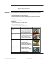
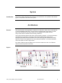
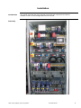
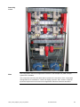
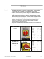
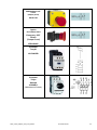
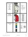
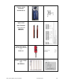
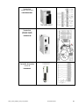
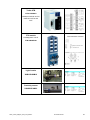
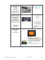
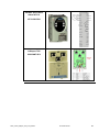
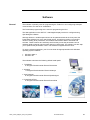
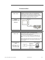
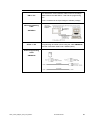
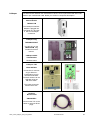
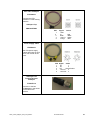
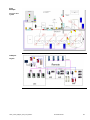
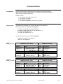
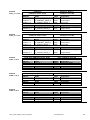

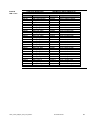
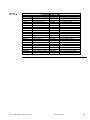
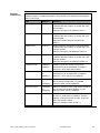
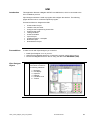
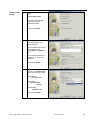
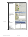
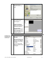
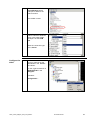
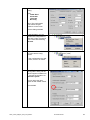
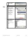
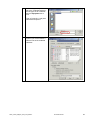
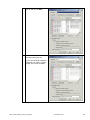
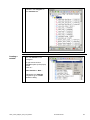
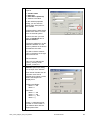
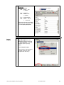
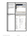
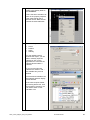
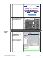
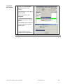
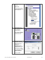
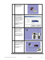
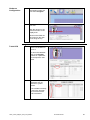
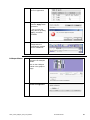
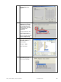
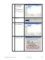
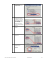
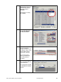
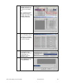
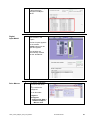
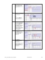
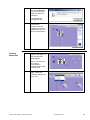
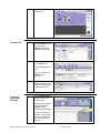
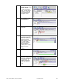
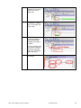
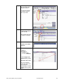
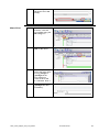
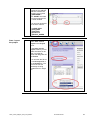
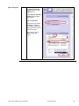
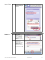
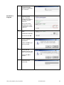

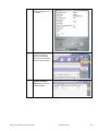
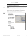
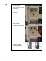
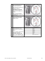
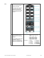
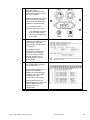
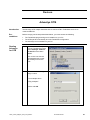
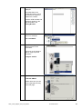
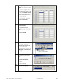
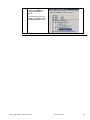
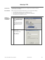
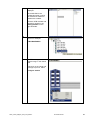
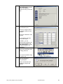

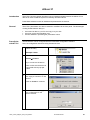
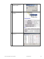
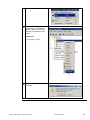
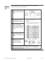

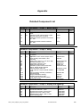
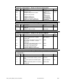
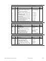
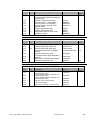
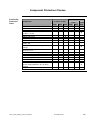
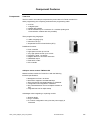
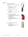
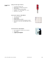
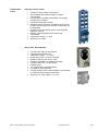

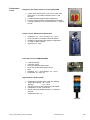
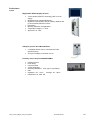


![OPTICAL DISTRIBUTION FRAME [Wall Mount Type]](http://vs1.manualzilla.com/store/data/005974674_1-8c415a2e9ec23148facf1df43798f7a3-150x150.png)