1
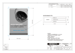
SERIES 1 USER MANUAL TYPE A MACHINES Type A Machines Inc. ©2014 Type A Machines Inc. This document is licenced by Creative Commons Attribution-NonCommercial-ShareAlike (CC BY-NC-SA) Users are free to remix, tweak, and build upon this work for non-commercial use, as long as users credit Type A Machines Inc. and license their new creations under the identical terms. Every effort has been made to ensure that the information contained in this manual is accurate. Type A Machines is not responsible for printing or clerical errors. Type A Machines 926 Howard St. San Francisco, CA 94103 www.typeamachines.com Products in this manual may be covered by US and International Patents. Type A Machines is a regestered trademark of Type A Machines Inc. Any products names mentioned in this manual are the property of their respective parties. V1.01 03.25.14 Type A Machines 2014 Series 1 User Manual Contents 1. What’s in the Box? ................................................................................................................................ 4 2. 3D Printing with Fused Filament Fabrication......................................................................................... 5 3. WELCOME TO YOUR 2014 SERIES 1 .................................................................................................... 6 3.1. Motion System ........................................................................................................................... 7 3.2. Winchester Tool Head/Extruder .............................................................................................. 8 3.3. Electronics .................................................................................................................................. 9 4. GETTING STARTED ............................................................................................................................. 10 4.1. Unpacking and Initial Setup ................................................................................................... 10 4.2. Power On .................................................................................................................................. 11 4.3. First Contact ............................................................................................................................. 11 4.4. Set the Build Plate in Place ..................................................................................................... 11 4.5. Loading Filament ..................................................................................................................... 12 5. SOFTWARE SETUP ............................................................................................................................. 14 5.1. Mac Users ................................................................................................................................. 14 5.1.1. KISSlicer ................................................................................................................................ 14 5.2. Windows Users ........................................................................................................................ 15 5.2.1. KISSlicer ................................................................................................................................ 15 6. BASIC OPERATION ............................................................................................................................. 16 6.1. .STL ............................................................................................................................................ 16 6.2. What file types can the Series 1 Read ................................................................................... 16 6.3. Slice in KISSlicer ....................................................................................................................... 16 6.3.1. Printing Resolution/Speed ..................................................................................................... 18 6.3.2. Infill ....................................................................................................................................... 18 6.3.3. Load your .STL file ................................................................................................................. 20 6.3.4. Slice! ...................................................................................................................................... 20 7. Run A Print ......................................................................................................................................... 22 7.1. The Series 1 Web Interface.................................................................................................... 22 7.1.1. Exploring the Interface........................................................................................................... 22 7.2. Load a G-Code File ................................................................................................................... 23 2 Type A Machines 2014 Series 1 User Manual 7.3. Print an Object! ........................................................................................................................ 25 7.4. Removing A Printed Object from the Print Surface ............................................................ 27 7.5. Prepare for Your Next Print ................................................................................................... 28 7.5.1. Replacing the Build Surface ................................................................................................... 28 8. SETTING UP WIFI ................................................................................................................................ 29 8.1. Connect to the printer using secure shell ............................................................................ 29 8.2. Edit the network configuration file........................................................................................ 30 8.3. Restart the onboard computer .............................................................................................. 30 8.4. Wifi Troubleshooting ............................................................................................................... 31 9. PERIODIC MAINTENANCE .................................................................................................................. 32 9.1. Tension Belts ............................................................................................................................ 32 9.2. Tighten Screws ......................................................................................................................... 32 9.3. Clean/Lube Linear Guides ...................................................................................................... 32 9.4. Clean Out a Filament Jam ....................................................................................................... 33 10. TROUBLESHOOTING ........................................................................................................................ 35 10.1. Z-Height Calibration .............................................................................................................. 36 10.1.1. Calibrating Z Height ............................................................................................................. 37 10.2. Calibrate the Build Plate ....................................................................................................... 38 10.3. Replace the Hot End.............................................................................................................. 40 11. SERIES 1 SUPPORT .......................................................................................................................... 41 11.1. Forum.TypeAMachines.com ................................................................................................ 41 11.2. Support Request .................................................................................................................... 41 3 Type A Machines 2014 Series 1 User Manual 1. What’s in the Box? Your Series 1 3D Printer! User Manual Quickstart Guide 3D Printed demo part + aluminum filament mount Sample PLA Power Cable Network Cable Wifi antenna Glass Build Platform Print removal spatula Glue stick for print surface preparation Upkeep Kit containing: x 7 MM wrench x 2.5 MM Hex Key x 2 MM Hex Key x 1.5 MM Hex Key x Insulated (Ceramic) Screwdriver 4 Figure 1.0.1 1 Type A Machines 2014 Series 1 User Manual 2. 3D Printing with Fused Filament Fabrication The Series 1 prints a 3D object by placing thin layers of plastic on top of each other until a finished object is built out of the layered plastic. To begin a 3D print, plastic is fed to the Series 1 in the form of “filament” (a long thin strand of specially formulated plastic, wound onto a spool). The Series 1 then heats the filament to its melting point and pushes, or “extrudes,” the melted plastic through the Extruder nozzle. The Series 1 moves the nozzle in a pattern while extruding plastic to draw a very thin cross section of the object that it is printing. The fan on the Series 1 Tool Head cools the newly extruded plastic, solidifying it almost instantly. After each layer is completed, the printer moves the object down a tiny amount, and then draws the next cross section of melted plastic on top of the cooled layer below. This method of 3D printing is called Fused Filament Fabrication, or “FFF”. Figure 2.0. 1 5 Type A Machines 2014 Series 1 User Manual 3. WELCOME TO YOUR 2014 SERIES 1 The Type A Machines Series 1 was developed in San Francisco, California, to be a big, fast, accurate, and reliable desktop 3D printer. It features a huge build volume, an innovative modular extruder replacement system, the “Winchester” quick release for fast filament loading, tip of your finger build plate calibration, and high precision stepper motors to for ease of use and high resolution printing. The 2014 model comes standard with integrated network controls for connections via WiFi and Wired Networking. Figure 3.0. 1 6 Type A Machines 2014 Series 1 User Manual 3.1. Motion System The Series 1 3D Printer is a Cartesian motion based printer system. This means it can move in 3 linear directions: the X, Y, and Z axes. It does this using pairs of precise hybrid stepper motors to drive the machine. The X and Y axes control the motion of the Tool Head. X axis moves the tool head left and right, and Y axis moves the Gantry forward and back. Both of these movements are made using high precision timing belts, linear guides, and motors. The Z axis moves the Build Surface up and down using a lead screw, linear guide, and stepper motor. The design of the Series 1 maximizes amount of machine area devoted to the buildable area. This results in a minimal machine footprint with a HUGE build volume. The maximum size of the object that can be built is 305mm along the ‘X’, 305mm along the ‘Y’, and 305mm along the ‘Z’ direction (12”x12”x12”). The Series 1 is accurate to 0.05 mm resolution along the x and y axis and up 0.05mm along the Z axis. The speeds at which the printer can move along each of these axes are among the fastest in the industry. Figure 3.1. 1 7 Type A Machines 2014 Series 1 User Manual 3.2. Winchester Tool Head/Extruder The Series 1 printer features the revolutionary Winchester tool Head. Designed and digitally fabricated in the Type A Machines offices at TechShop San Francisco, the Winchester Tool Head is designed to allow quick release and loading of both filament and the open source, industry standard “groove mount” Hot End. It has proven to be incredibly reliable and easy to service and clean. With this advancement the Series 1 is capable of reliably extruding filament up to 230° C. Standard extrusion temperatures vary per material and per supplier—refer to the filament packaging for recommended extrusion temperatures. Figure 3.2. 1 8 Type A Machines 2014 Series 1 User Manual 3.3. Electronics The Series 1 uses an all open source electronics system. It consists of a Beagle Bone integrated microcontroller, Arduino based RUMBA driver control board, and Pololu driver chips. The Beagle Bone is the ‘brain’ of the printer. It interfaces with your computer via its own web interface to load the control instructions onto the printer and to drive it. The RUMBA serves as the motor control and power distribution system for the Printer. It translated G-code commands coming from the Beagle Bone into motion and heat instructions that it sends out to the components of the printer. It also serves as the connection point for most of the wiring in the machine. This is where the sensors and heaters in the Tool Head and the fans connect. The last section of electronics is the motor drivers. There are 4 motor drivers per machine, one each to drive the X,Y,Z and Extruder motors. These little chips take the instructions and Power from the RUMBA and directly control the motors. They send hundreds of commands per second! The electronics compartment is cooled by a fan to keep things from overheating. For a schematic and detailed real world plan of the electronics please see the TROUBLESHOOTING section of this guide Figure 3.3. 1 9 Type A Machines 2014 Series 1 User Manual 4. GETTING STARTED 4.1. Unpacking and Initial Setup Time to get started! If you haven’t already, now is the time to see what your printer looks like out of the box. Carefully remove the printer from the carton. If the printer is difficult to remove, cut open the edges of the box. Attempting to force the printer out of the box may break it. Remove the packing material from around the printer. The Gantry and Tool Head have been tied down to protect it in transit. Remove the yellow strapping and the Gantry and Tool Head should now move freely. The Spool holder and sample parts are in the box strapped to the platform arms of the machine. Open the box: remove the spool holder and attach it to the top of the machine with the thumb screws. The build surface and platform are in the long box strapped below the platform arms. Carefully open the box and remove the build platform assembly. The side panels are stowed to protect them during shipping, remove them from the box, peel off the protective paper and install them on the sides of the machine with the countersunk side facing out. Check your package contents to confirm that your Series 1 shipped with all parts. 10 Type A Machines 2014 Series 1 User Manual 4.2. Power On It’s time to bring the printer to life. Plug the included power cord into the power port on the back panel of the machine. Plug the wall end of the cable into an available socket. Flip the main power switch on. Press the front panel switch and you should see it glow white. Congratulations! You’re one step closer to printing! 4.3. First Contact Your Series 1 comes standard with 3 different methods of connection: USB, Wired Network, and Wireless networking. The easiest to set up is a direct wired Ethernet connection to the printer. Simply plug the included Ethernet cord into the back of your printer and connect it to an open port on your router or base station. Open a web browser and direct it to series1-XXXX.local:5000 ‘XXXX’ is the serial number on the front of your machine You should now see the Type A Dashboard on your browser. 4.4. Set the Build Plate in Place Your Build Plate comes prepared with a glass build surface adhered to the printable area. The glass square is your Print Surface for you to print directly onto. In order to prepare the surface for printing open the included glue stick and smear a thin layer across the platform. It will dry almost instantly and provide good hold for you prints. The Print Surface can be marred by oils on your fingertips, so avoid touching the surface unnecessarily. After several prints you can wash off the glue with warm water and re-apply the glue. See Section 7.5.1 Replacing the Build Surface, to learn how to use blue tape or other alternatives to prep it for printing again. 11 Type A Machines 2014 Series 1 User Manual To place your Build Plate, rotate the surface so that the aluminum is angled towards you. Slot the four holes on the outside corners of the Build Surface onto the four standoff assemblies on the Series 1 Build Platform. Press down gently to depress the springs on the standoff, then slide the Build Surface back to lock it into place. Your Build Surface is now correctly in place. The standoff height and bed leveling is calibrated during the final quality control procedures before your Series 1 ships. You should not need to make any adjustments to the standoff assemblies for your initial print. If you notice problems with your first print and suspect the standoffs have shifted, refer to the troubleshooting guide for the Build Surface calibration procedure. 4.5. Loading Filament Open the Winchester spring lever by resting your thumb on the left edge of Tool Head and using your index finger to pinch the spring lever open. The top of the lever will swing left. With the lever in the open position, you will notice a small hole in the upper surface of the Winchester clamp plates, in between the lever and the pinch-wheel. This small hole is the filament loading aperture. Trim the end of your PLA back ½” to ensure a clean end. Fully 12 Type A Machines 2014 Series 1 User Manual insert the end of your PLA into the aperture, and gently release the spring lever. The PLA should now be pinched in between the pinch-wheel and the spring lever and fully inserted into the filament loading aperture. Note: All Filament is Not Created Equal. Please be aware that the quality of PLA can vary substantially. Caution: Poor quality PLA may damage your Series 1 and it will definitely interfere with your ability to create a successful print. High quality filament is available through the Type A Machines online store: www.typeamachines.com/products 13 Type A Machines 2014 Series 1 User Manual 5. SOFTWARE SETUP To get your Series 1 ready and printing the only program you need to install is a slicing engine. This is the program that takes the model information from your CAD program and converts it into machine readable code to tell the printer what to do. We have precompiled installation packages that are available for download on our website. Just select the System you are running and download. All the installers are included and in sequence. Go to typeamachines.com/download to get your installer package. 5.1. Mac Users No need to set up drivers, your Mac comes preconfigured to play nice with our printer. Once your download is completed, Unzip the Mac installer package and move the unzipped folder somewhere convenient on your drive (most users prefer the desktop). 5.1.1. KISSlicer In the unzipped file you will see a folder called 02_KISSlicer. Again the Application is ready to go no install required. Along with the KISSlicer Application, this file contains the configuration files to slice your files. Type A Machines has developed and optimized these settings for your best possible printing. You MUST have these configuration files in the same location as your KISSlicer application. Note: If you start the app and it gives you a warning about not being able to find configuration files, just move the included files to wherever you have your KISSlicer application placed. Congratulations! Your software is now set up and you’re ready to slice your digital models into printable code! 14 Type A Machines 2014 Series 1 User Manual 5.2. Windows Users The first step is to download the installation package for your operating system. Select either windows 32 or 64 bit. Once your download is completed, unzip the installer package and move the unzipped folder somewhere convenient on your drive (most users prefer the desktop). 5.2.1. KISSlicer In the unzipped file your will see a folder called 02_KISSlicer. Again the Application is ready to go-no install required. Along with the KISSlicer Application, this file contains the configuration needed to slice your files. Type A Machines has developed and optimized these settings for your best possible printing. You MUST have these configuration files in the same location as your KISSlicer application. Rightclick on the KISSlicer application to create a shortcut on your desktop for easier access. Note: If you start the app and it gives you a warning about not being able to find configuration files, just move the included files to wherever you have your KISSlicer application placed. Congratulations! Your software is now setup and you’re ready to slice your digital models into printable code! 15 Type A Machines 2014 Series 1 User Manual 6. BASIC OPERATION 6.1. .STL The first step in the process from 3D Model to 3d Print is to export your 3D model from your modeling program as a .STL file. STL is an industry standard for 3D printing files. Your model must be a closed, ‘water-tight’ mesh. This is critical to producing a quality print. There are many software modeling tools and Mesh Repair utilities you can use for this. We recommend using Rhinoceros 5.0, it’s a robust CAD platform with many easy tools for modeling, analysis, and repair. 6.2. What file types can the Series 1 Read The Series 1 reads instructions about how to move the extruder and build platform, and when to extrude filament, from a file called a G-Code file. G-code is produced by ‘slicing’ software. G-code files can end “.gcode” or “.gco.” GCode files are specific for each type of printer. If you’d like to create your own g-code file, then you’re going to need to slice it first. We have included in your download package a few premade GCode files for you to get printing right out of the gate, if you’d like to use these files on your new Series 1, then you’re ready to print. 6.3. Slice in KISSlicer After following the instructions for the installation of KISSlicer your program will be configured correctly to output prints to the Series 1. First open the program. It will load up a simple home screen. On the right you have the file Figure 6.3. 1 16 Type A Machines 2014 Series 1 User Manual bar and below are your settings. The first time you open KISSlicer it will not have the visualization of our print bed loaded. To visualize the Series 1 click the ‘Printer’ tab in the settings box. Then in the bottom right corner of the settings box click the box marked ‘…’ (figure 6.3.1). Open the file location where you unzipped the Type A Machines Setup Package. The Setup Package includes a model of the Print bed for your reference. Open the file called “platform (figure 6.3.2). Figure 6.3. 2 Figure 6.3. 3 KISSlicer now shows a visualization of the Series 1 Build Platform (figure 6.3.3). 17 Type A Machines 2014 Series 1 User Manual Figure 6.3. 4 6.3.1. Printing Resolution/Speed In the Settings area, select the tab marked ‘Style. This tab allows you to control the resolution, and thus the speed of your print (figure 6.3.4). There are a range of settings from ‘Draft’ through Super-Fine. At Type A, we usually use Fine setting. It’s a balance between speed and resolution and it’s a great place to start. Figure 6.3. 5 6.3.2. Infill 18 Type A Machines 2014 Series 1 User Manual From the ‘Style’ tab, you will see the Infill slider control at the bottom of the settings are. This controls the amount of plastic filling that will support the inside of your 3D printed object. You can toggle the infill from solid, which prints VERY slowly, but results in very strong prints, to to 2.5% infill, which prints more quickly but has a lower finished strength (figure 6.3.5). Figure 6.3. 3 Figure 6.3. 4 19 Type A Machines 2014 Series 1 User Manual 6.3.3. Load your .STL file To load a .STL file, click ‘OPEN’ and then navigate to the desired STL file. To use one of the supplied Type A Machines .STL files, open the file where you unzipped the Setup Package and open the folder called Test Prints” select one of the included .STL files (figure 6.3.6). Figure 6.3.7 shows a visualization of a loaded .STL file. If the file you loaded looks very small you may be having a unit conversion problem. To fix this, right click on the image of the .STL in the upper right hand corner (figure 6.3.7) and click “inch->mm”. This will scale your model correctly. Figure 6.3. 5 6.3.4. Slice! When you are satisfied with your settings click “Slice” in the upper right hand corner to slice your .STl (figure6.3.8). 20 Figure 6.3. 6 Type A Machines 2014 Series 1 User Manual The visualization will turn green when slicing is completed. Click the ‘Models+Paths’ button above the visualization to switch views. This is now a visualization of your GCode. You can now use the slider on the right of the visualization to slide your slice through the model. If you are satisfied that your model sliced correctly, click ‘Save’ at the upper right hand corner of the screen and select a location to save your G-Code for printing. 21 Type A Machines 2014 Series 1 User Manual 7. Run A Print 7.1. The Series 1 Web Interface Now it’s time to get that printer moving. Confirm that the Ethernet Cable is connected to your router and your computer on the same network as the printer. Launch your Web Browser of choice and navigate to your printers home page at series1-XXXX.local:5000 remember ‘XXXX’ is your serial number found on the front of the machine. For Wifi setup instruction see chapter 8 . 7.1.1. Exploring the Interface The interface should load in a moment. If it does not check to make sure the USB cable is firmly connected and the printer is turned on. If the problem persists please see Connection Problems in the troubleshooting guide at the back of this manual. 22 Type A Machines 2014 Series 1 User Manual 7.2. Load a G-Code File Figure 7.2. 1 Your printer ships pre-loaded with sliced models to get you up and running. To load one of the supplied G-Code ) button in the “Files” Tile. Select any of the premade G-CODE files. If you have another files, click the “Load” ( G-Code file sliced and saved on your computer then click “UPLOAD” select it and open it. 23 Type A Machines 2014 Series 1 User Manual Figure 7.2. 2 Note: The web interface with accept STL files but it will not allow you to print them (yet), make sure your uploaded file is a GCODE After the file is loaded you will see a Status appear in the Status window above the File Window. It will give you the estimated filament use, as well as the estimated print duration and height. The estimate will start out 5-15% off and becomes more accurate as the print progresses. Note: large G-Code files may take a few seconds to load. 24 Type A Machines 2014 Series 1 User Manual 7.3. Print an Object! Now it’s time for the magic to start! Take a deep breath, make sure the filament is able to feed freely, and click print. When you do this a few things should happen: 1) your printer will move all three axes to ‘home, ’2) It will then move to the front-center of the build surface and pre-heat. You can watch it’s progress in the temperature graph. 3) When the printer reaches temp it will extrude a small amount of filament material. Caution: The extruder is hot and you may burn yourself if you touch the extruder or the extruded filament. You can manually wipe this away with a tweezer, or it will wipe it away on the build surface. 4) The head will move to begin creating your print. 5)The fan should turn on. This helps solidify the printed part. Note: If the fan doesn’t turn on automatically, you can turn it on manually by typing ‘M106 S255’ in the Terminal tab command line. To learn more manual commands, visit the Type A Machines support forum. 25 Figure 7.3. 1 Type A Machines 2014 Series 1 User Manual It’s a good idea to watch your first layer complete before walking away. This is the most critical part of the print and chances are if your first layer is good the rest will be too. The extrusion should spread onto the print surface and strongly adhere to it. It should not be stringy nor should it be crushed into the surface. Your printer is calibrated for correct initial extrusion height during quality control, and should not need adjustment out of the box. If you have a problem with setting this level refer to Setting Z Height in the Troubleshooting area of this guide. WOOOHOOO! CONGRATULATIONS! You have just started your first 3D print with The Type A Machines Series 1. Time to kick back, relax, and start designing your next print! 26 Type A Machines 2014 Series 1 User Manual 7.4. Removing A Printed Object from the Print Surface When your print completes, the gantry and head will move away to the back of the machine. Many times depending on your object, you will be able to pop it off the surface by gently prying it off. If your finished part does not come off easily you can quickly and easily remove the build plate to make removing the printed object. This is particularly useful for prints with a large footprint. To remove the build plate, wrap your hands around the sides of the build platform as shown. With your thumbs on top of the surface press down gently to depress the standoff springs. Now slide the surface towards you to detach it from its bolts. Once the build surface has been removed from the machine, it is easier to work the part to pop off. Try to get a corner off then, using a putty or butter knife placing careful attention to keep your fingers out of the way of the blade, carefully pry the rest of the part off. If your part is really stuck take the entire platform over to your sink, wash the surface around the print in warm water to loosen the glue. Use a putty knife to work the warm water under the part. Once your print is loose, you should be able to pull the rest of it off of the surface. Note: This water method of print removal should be used if there is any amount of force applied that may crack the glass. Be patient and let the warm water work. If you crack the glass a replacement can be ordered from the typeamachines.com webstore.. 27 Type A Machines 2014 Series 1 User Manual 7.5. Prepare for Your Next Print You will be able to print multiple times before your Print Surface will need to be replaced. In order to promote good adhesion of the initial print layer, avoid touching the Print Surface with your fingers so as not to transfer oils on the Print Surface. 7.5.1. Replacing the Build Surface After multiple prints, you may notice that portions of the printed object may not be sticking. This indicates that it’s time to replace your Print Surface. Your print surface can be resurfaced using the included glue stick, sign vinyl purchased from Typeamachines.com, or by using 2 inch wide blue painter’s tape. You may wish to vary your level of adhesion based on your print type. For general use the included Glue Stick works well. It provides a medium-low amount of adhesion and is available in the Type A Machines webstore. For more delicate prints and easier removal, 3M 2093-EL tape provides a low-medium amount of adhesion. 7.5.1.1. Prepare the Build Plate with blue (painter’s) tape: To prepare the Build Plate with blue tape, peel a length of tape about twelve inches long, align it with the recessed guide at the bottom of the Build Plate and adhere it so that a small edge extends over the outside of the guide to the left and right. Peel a second portion of tape twelve inches long, and place it edge to the edge from the strip already placed on the Build Plate. For a clean bottom layer, do not overlap the tape. Repeat this process until the entire recessed square guide area is covered with tape. Use a razor or breakaway knife by running it down the recessed guide to trim away any excess tape. Your tape print surface should now be solidly adhered to the build plate without any bubbles or voids. Your print surface is now prepared. 28 Type A Machines 2014 Series 1 User Manual 8. SETTING UP WIFI V0.1 Remove the wifi antenna from the box and screw it on to the back of the printer. It’s a good idea to set your printer up in the same room as your wireless router for the first connection. Once you have it working you can move it away but make sure to stay within wifi range. Your printer ships with WiFi tested and configured for our factory. Since everyone’s WiFi network name and password are different you will need to set up the printer to get onto your network. To do this you will need to use an SSH command line to talk directly to the printer’s operating system. The first step is to get an SSH program. Mac users only need to use their preinstalled Terminal application. Windows users will have to install an additional program. The easiest for those running the Chrome Browser is the Chrome Secure Shell Extension: https://chrome.google.com/webstore/detail/secure-shell/pnhechapfaindjhompbnflcldabbghjo?hl=en Windows Prerequisites: x Bonjour x ssh client (Bitvise SSH, or KiTTY, PuTTY, etc.) Linux prerequisites x Avahi (Bonjour/zeroconf support. Often already installed) Mac prerequisites x none This is the temporary procedure for setting up WiFi on a printer connected to a wired or wireless network. This will get easier soon. For first time setup plug your printer directly into your Wireless router or base station with the included Ethernet cord. 8.1. Connect to the printer using secure shell On Mac or Linux, use ssh in the terminal. On Windows use your preferred ssh program. username: ubuntu password: ubuntu hostname: series1-bXX.local where XX is the serial number on the front of your machine omitting the zeroes before ‘b’. On Mac or Linux, just run the following in a terminal 29 Type A Machines 2014 Series 1 User Manual ssh [email protected] 8.2. Edit the network configuration file Once you’re logged in to the printer, run the following command to edit the config file using the nano editor. You will be prompted for the password again because this command requires admin privileges. sudo nano /etc/network/interfaces You need to edit the part of the file that describes the wireless network, called wlan0. Fill in your network name and password in the part of the file shown below. # wireless network interface auto wlan0 iface wlan0 inet dhcp wpa-ssid "Your WiFi Network Name" wpa-psk "Your password" Hit control-x to exit nano and save the file. 8.3. Restart the onboard computer sudo reboot While it’s restarting, unplug the Ethernet cable. Your printer should show up on your wireless network when it’s done restarting. This can take up to two or three minutes. You can now re-launch your web browser and connect to the printer wirelessly. 30 Type A Machines 2014 Series 1 User Manual 8.4. Wifi Troubleshooting When you first turn the printer on the web interface may not come up automatically. This is due to a bug in the server system we are working on it but for the time being a fix is to SSH in to the printer as described above. Then Restart Octoprint: sudo service octoprint restart You will then have to enter the password again (“Ubuntu”) then the service will restart. Direct your browser to the printers address and it should show up within 15 seconds, if it does not contact support. 31 Type A Machines 2014 Series 1 User Manual 9. PERIODIC MAINTENANCE Your machine is designed to require very little upkeep and maintenance. In some instances, the Series 1 has run 24 hours a day for months without needing to service. But depending on the environment that the Series 1 is kept in, and the type of use, you may need to do some basic maintenance from time to time. 9.1. Tension Belts For optimal accuracy your belts should remain tight. You can test their tightness with a finger, it should spring back with almost a guitar string tension. You will need the included 7mm wrench and 2.5mm Hex Key. First use the 7mm wrench and 2.5mm Hex Key to loosen the Y or X Tension Adjust Bolt. Tension the belt by pulling on the adjustment bolt with the wrench, then tighten the bolt with the hex key. 9.2. Tighten Screws In rare cases due to vibration of the machine screws can come loose over time, the critical components all have locking nuts to prevent them from failing. Screws can loosen in very dry environments or when the machine has been moved many times. In your included toolkit there is a 2mm wrench that is the perfect size for tightening most of the bolts on the machine. In very rare cases the Hot End mounting clamps can come loose. This will be apparent by the hot end wobbling when touched or while printing. To fix this turn the machine off and allow the head time to cool down. Remove the front clamp over the hot end (follow the Replace a Hot End procedure if unsure of how to do this). Using the 2.5mm hex ke, tighten the now exposed bolts. This should alleviate any wobble in the clamp. 9.3. Clean/Lube Linear Guides In dusty environments the guides can pick up dust and floating particulates. After a great deal of use this can eventually cause motion problems and may damage the bearings. Clean the rods with an alcohol dipped clean rag, microfiber cloth, or paper towel. After any accumulated matter has been removed re-lubricate the rods using only White Lithium Grease. With the machine turned off, move the gantry and Tool Head back and forth to work the grease into the rods and bearings. This procedure will reduce running noise as well. 32 Type A Machines 2014 Series 1 User Manual 9.4. Clean Out a Filament Jam In the course of normal operation your hot end may become clogged. This can happen from dust on your filament, changes in humidity, or a variety of other factors. Luckily these clogs are generally easy to clear. Blow off any filament powder that may have accumulated due to the jam. Blowing on the Pinch wheel will clean any power there that may continue to cause bad prints. You may wish to clean it with a small wire brush or a can of compressed air. Power on your Series 1, connect to it and Manually set the temperature to 185-200 Degrees C. Once it reaches temperature, remove any filament from the filament Aperture (figure 8.4.1). Caution: The Hot End is now hot and can cause burns if you touch it! Take a length of .013” music wire (available through McMaster Carr: 8907K95) and thread it up through Extruder Nozzle. The music wire should come out through the Filament Aperture with a small bead of plastic on it. Immediately pull the wire up through and out of the Tool Head. Figure 8.4. 1 Figure 8.4. 2 Figure 8.4. 3 Caution: do not leave the music wire in the Hot End. Leaving the music wire in the Hot End will allow it to heat up and may cause burns. If the music wire does not come through the aperture, pull it back out of the nozzle and remove the front clamp from the Tool Head by following the ‘Replace the Hot End’ instructions. Thread the music wire through the loosened Hot End. The music wire will now pass through the Hot End. Thread the music wire through again. You can now reassemble the front clamp. 33 Type A Machines 2014 Series 1 User Manual Insert high quality filament end into the Filament Aperture. Manually push the filament into the aperture. You should be able to see it come out of the Extruder Nozzle with steady, but not excessive force. If you are unable to get filament to come out manually, repeat the unclogging procedure. Now that the filament jam is cleared, make sure your hands are outside the machine and click “extrude” to push some plastic through using the Winchester. Melted filament should come out through the extruder nozzle. If it does not or you hear the motor skipping or making noise, repeat the unclog procedure. If after 3 attempts the Hot End is still fouled you may need a replacement. Hot Ends can be purchased through the Type A Machines store. Note: Hot ends are a consumable part. They do wear out over time, and eventually replacement will become necessary. Users have demonstrated 24/7 use of a single hot end for over 8 months before replacement, however individual results may vary. 34 Type A Machines 2014 Series 1 User Manual 10. TROUBLESHOOTING Problem/Symptom Cause Solution Initial Print Layer Fail Build surface too high reset Z height (page) Improper print surface material Print directly onto blue print surface (page) Improper build platform recalibrate build platform standoffs (page) Improper slicing settings Adjust speed, re-slice hot end clog de-clog hot end filament tangle clean extruder, reload filament hot end connector unplugged plug in connector unable to reach temp cycle machine and reconnect web interface None of the above contact type a machines support motor current settings adjust potentiometers dirty rods lubricate rods belt tension adjust belt tension improper print surface material Replace print surface with appropriate Accidental print directly onto Replace acrylic build surface machine unplugged plug in machine, flip switch calibration No/Poor Extrusion No/Loud Motion Object will not detach from build surface acrylic build surface No lights/response material (EG: blue tape) 35 Type A Machines 2014 Series 1 User Manual 10.1. Z-Height Calibration Figure 9.1. 1 The Series 1 features an easily accessible at the back right of the build volume which can be adjusted to increase or decrease the height for the first layer of printing. The knob is set to the correct height during quality control, but it may require some refinement if you change something or want a different layer height (figure 9.1.1) The Z height adjustment knob works by triggering a micro-switch mounted to the platform of the Series 1. It should be adjusted to trigger the switch when the build surface is just below the tip of the extruder nozzle. Caution: Before setting the Z height make sure the Hot End is cool. Failure to ensure that the Hot End is cool may result in damage to the machine. To test the Z height use a piece of paper. With the hot end cooled off connect to the printer, navigate to the Control panel and click the HOME button showing a house (figure 9.1.2). When the platform stops moving upward it has reached the home position. You should be able to slide a piece of paper easily under the tip of the hot end Figure 9.1. 2 36 Type A Machines 2014 Series 1 User Manual between the extruder nozzle and Build Surface. There should be some resistance but the paper should move freely. If the gap is too small to slide a sheet of paper between the nozzle and the Print Surface, the Z height is too high. Alternatively if the sheet of paper can be slid under the nozzle with no resistance, your Z height is too low. 10.1.1. Calibrating Z Height Press ÏZ 10 to move the platform away so you can adjust the set screw (figure 9.1.3). At the top of the build platform structure there is a graphic that shows which direction to turn the screw for the desired adjustment (figure 9.1.4). It is best to go in ½ turn increments at first. Then either Full turn or ¼ turns each adjustment depending on how far off you are trying to adjust it. If the Extruder Nozzle is too close: Move the platform away from the hot end and increase the gap by turning the screw to the right (clockwise). If the Extruder Nozzle is too far: Move the platform closer to the hot end and decrease the gap by turning the screw to the left (counter-clockwise). After each adjustment to the screw press home and then +10 Z and repeat the paper test procedure. 37 Type A Machines 2014 Series 1 User Manual 10.2. Calibrate the Build Plate Your build plate is calibrated before it leaves the Type A Machines Factory to print the initial layer of an object at an even height. The Build Plate Calibration Bolts feature two finger nuts. A bolt passes through the Build platform, with one nut above and one below. These nuts work together to adjust the height of the Build Plate and then to lock the adjustment in. If you are experiencing problems with first layer adhesion when a portion of the first layer is properly adhered and another portion is not, first replace the blue tape print surface and try again. If problems persist you MAY need to re-calibrate your build plate. 38 Type A Machines 2014 Series 1 User Manual To adjust one corner of the Build Plate higher, gently loosen the lower nut and tighten the upper nut, then tighten the lower nut to lock the adjustment in. To adjust one corner of the Build Plate lower, gently loosen the upper nut, and then tighten the lower nut to lock it in. Caution: make sure your hot end is cool. Clear the build plate of any prints or other materials. Place the included 7mm wrench on the build plate in the front right corner (figure 9.2.1). We will use the open head of the wrench as a milled standoff block. Move the tool head to be directly over the wrench. Move the Platform so it is almost touching the wrench (figure 9.2.2). Turn off your machine. Now adjust the two finger nuts until the wrench comes in light contact with the Extruder Nozzle. You should be able to move the wrench around under the head while feeling light resistance from the contact. Remember to tighten the lower nut to lock the adjustment in (figure 9.2.3). Manually move the Tool Head each of the four corners, place the wrench beneath the extruder nozzle and repeat knurled nut adjustment procedure. You build plate should now be Calibrated. Confirm this my moving the wrench and head to the front right. You may need to tweek this bolt since you have adjusted the others. Figure 9.2. 3 Figure 9.2. 2 Figure 9.2. 1 39 Type A Machines 2014 Series 1 User Manual 10.3. Replace the Hot End For an extended guide please see our Knowledge Base Entry To replace a hot end first turn off the machine and disconnect from your computer. Make sure the hot end is cool. Unscrew the Hot End Clamp access bolt using the 2.5mm Hex Key. After the front of the clamp is off use the hex key to pop the hot end out of the groove mount slot. Disconnect the Thermister and Heater Wires (the purpleclear and orange-green wires). Take great care to disconnect them gently. Only apply pressure on the black connector bits themselves. The connectors are easily damaged. Set the bad hot end aside. Slide the new hot end Figure 9.3. 1 into the mount with the wires facing left. Reconnect the connectors carefully. Screw the front clamp back on. You have just installed a new hot end! 40 Type A Machines 2014 Series 1 User Manual 11. SERIES 1 SUPPORT 11.1. Forum.TypeAMachines.com If you’re having trouble getting a print to run smoothly, and you haven’t been able to find a fix in this manual, the next place to look is Forum.TypeAMachines.com. The Type A Machines Forum is privileged to have an active, well informed, and helpful user group. The Forum is also one of our favorite places to announce product giveaways, betas, and competitions. And it’s a great place for you to show off your awesome prints! 11.2. Support Request To initiate a support request, please visit support.typeamachines.com e-mail [email protected]. 41 www.typeamachines.com [email protected] +1(415) 371-9682 TYPE A MACHINES SERIES 1 Model: 2014 SPECIFICATIONS S114SA1 Printing Specifications Technology: FFF (Fused Filament Fabrication) Filament Diameter: 1.75mm Hot End Type: Nozzle Diameter: Hot-End Max Temperature: Groove Mount 0.4mm 235°C (455°F) Build volume: 1728 in3 (28.37 liters) Build AreaX: Build Area Y: Build Area Z: 12.0” (305mm) 12.0” (305mm) 12.0” (305mm) Layer Resolution: Extreme50 Micron High 100 Micron Medium 150 Micron Low 200 Micron Draft 250 Micron Positional Accuracy: X/Y: 6.67 Microns Z: 0.625 Microns Print Speed: 30-120mm/s Travel Speed: 150-250 mm/s Physical Specifications: Overall Width:18.35” (765.75mm) Height:22.51” (571.80mm) Depth:18.05” (458.67mm) Machine Weight: 30lbs (13.60kg) With Spool of PLA and holder attached Width:18.35” (765.75mm) Height:31.55” (801.48mm) Depth:20.98” (533.02mm) Shipping Box: Width:20” (508mm) Height:24” (609.6mm) Depth:20” (508mm) Shipping Weight: 35lbs (15.87kg) Software Specifications Slicing Software: Supported Packages: KISSlicer, Cura Supported file types: STL, OBJ, AMF OS: Windows 32/64 Bit 7+ Linux: 32/64 Bit 12.04+ Mac; 32/64 Bit 10.6+ Control Software Series 1 Octoprint (included) Compatible: Pronterface, MatterControl, Repatier file type: .GCODE .GCO Processor 1 Ghz ARM Linux Processor 8GB+ expandable onboard Storage Connectivity Device port: Expansion ports: 1x USB ‘B’ 2x USB ‘A’ + USB expansion bus Wifi:B/G/N 1Ghz WiFi Security: WEP/WPA/WPA2 100MB Ethernet Operation Envelope Operating Voltage: 110-240 VAC Internal Voltage: 24 VDC/5VDC Operating Temperature: 60-99°F (15-37°C) Operating Humidity: 5-95% Storage Humidity: 5-95% Storage Temp:32-99°F(0-37°C) Operation Noise: 40-70 dB