1
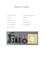
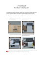
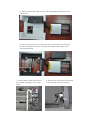
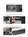
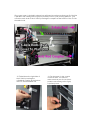
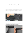
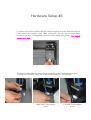
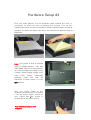
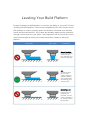
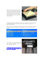
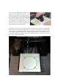
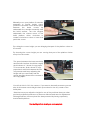
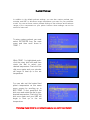
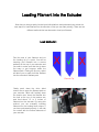
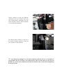
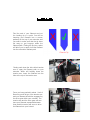
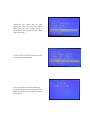
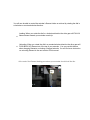
WANHAO Duplicator i3 User Manual Rev. C © Wanhao USA 2015 www.wanhaousa.com Safety WARNING: The components on the Duplicator i3 generate high temperatures and move extremely fast. Reaching inside of the Duplicator i3 while it is in operation may cause injury. Stay clear of the printer frame perimeter while the machine is in operation. Always control the Duplicator i3 from the rotary dial on the front of the printer or via the computer software. Never push or pull any of the components by hand. After a print, make sure your printer is off and that your nozzle is no longer hot before removing a model from the printer. WARNING: The Duplicator i3 is a heavy machine and extra caution is advised when lifting/moving the printer. Failure to properly lift/move the printer can result in injury. CAUTION: When opening the Duplicator i3 for service, ensure that the power supply is turned off and the power cord is disconnected from the wall socket. Failure to do so can result in electrical shock. CAUTION: Only use the stock power supply provided with your Duplicator i3. What's In The Box Duplicator i3 3D Printer 10M (~30FT) PLA Filament Pack Control Box USB Cable Model Removal Tool SD Card Kit Hex Screws & Key Kit Platform Tape Sheets Filament Spool Holder Power Supply Cable Spool Holder Stand Unboxing & Hardware Setup #1 Your printer was packed securely to ensure safe shipment and storage. Make sure to remove shipping ribbons, foam inserts, and packaging carefully to prevent damage. Make sure to begin the unboxing by laying the outer printer box on a dry, clean, and stable work surface (table or floor). 1. Cut off shipping ribbons & open the outer printer box. 2. Remove the cardboard accessories box. 3. Remove the top-layer foam insert. 4. You should now see your printer base and control box NOTE: Never lift your printer by any electronics cables! We also recommend that you keep your printer box for future transport and long-term storage. 5. Remove the printer base from the foam packaging and place onto a flat surface. 6. Remove and place the control box next to the printer base. Remove the second-layer foam insert revealing the square tower frame & the extruder assembly. 7. Cut the white ribbon that secures the extruder assembly to the tower frame. 8. Remove the tower frame and stand it up vertically on the flat surface. 9. Insert the printer base into the tower frame and match the screw slots where the two frames meet. 10. Locate the screws (4 PCS) in your cardboard accessories box and use them to screw the tower frame to the printer base. Start by screwing in one screw from the outside of the frame towards the inside of the frame. 11. Lastly, turn your printer on it's side and insert a screw from the inside of the frame towards the outside of the frame. This will lock in your frames and prevent shifting of during operation. Once your tower is locked in placed you will need to make sure that your X-Axis (the 2 parallel rods running left-to-right) is perfectly level to your printing platform. You can raise each side of the X-Axis by turning the couplers at the bottom of the Z-Axis threaded rods. 12. Raise/lower the right side of the X-Axis by turning the cylindrical coupler at the bottom of the Z-Axis threaded rod. 13. Do the same for the coupler on the left side. You need to make sure that your X-Axis (the 2 parallel rods running left-to-right) is perfectly level. Hardware Setup #2 Find the Spool Holder Stand and the Control Box. Place the stand into position on top of the Control Box by aligning the two screw slots so that they are at the rear of the stand. Insert 2 screws and secure the stand to the Control Box. Find the Filament Spool Holder and unscrew 1 of the end nuts on the side with 2 end nuts. Place the holder through the hole in the stand and secure the previously removed end nut back into place. Hardware Setup #3 To protect your printer against damage during shipping we have disconnected the Z-Axis and X-Axis stepper motor cable connectors. You will need to insert each connector into their corresponding sockets before using your printer. The longest cable is for X-Axis. The other 2 cables near the sides of your printer are for the Z-Axis stepper motors. To insert the connector simply line up the terminals and give a slight push. Right side Z-Axis stepper motor. Left side Z-Axis stepper motor. Hardware Setup #4 Find your build platform (it’s the aluminum plate towards the front of your printer on which you will be building your models). Tear off one masking tape sheet and cover the platform with the sheet being as smooth as possible. You will be printing on this sheet. You can also use painter's tape as a substitute. Note: Your printer is able to operate using 2 voltage options: 110V and 220V. Make sure you set the switch to the correct voltage according to your country's power supply voltage (USA uses 110V). Before connecting anything, make sure that the Duplicator i3 power switch is in the OFF position. Find your Power Cable in the cardboard accessories box and plug it into the power supply socket on your Control Box (the socket is located next to the power switch). Your Hardware Setup is now complete. Powering On Your Printer Once you have prepared your printer for operation press the power switch on the back of your control box. The power switch is located next to the power cable socket. If you are not able to turn your printer on please re-check all of your power cable connections. Upon turning on your printer you should see the WANHAO logo while your printer's firmware boots up and then ultimately the status monitor screen. While your printer is in operation the status monitor screen will show you real-time information pertinent to your printer. Use the rotary dial on the front of your control box to browse through the LCD menu. When you wish to make a selection on the LCD menu push-click the rotary dial. Leveling Your Build Platform Properly leveling your build platform is crucial to the quality of your print. The term "leveling your build platform" refers to the manipulation of the four corners of your build platform in order to properly space the distance in between your extruder nozzle and the build surface...this is what will ultimately determine the resolution, strength, and accuracy or your prints. The image below will show you the correct and incorrect height at which your nozzle should be in relation to the build platform: SIDE VIEW END VIEW COMMENTS Nozzle Too High: Insufficient contact area resulting in poor adhesion and extrusion skipping. OK: Filament pushed into the build surface slightly to maximize surface area contact while still allowing good extrusion flow. Nozzle Too Low: Not enough clearance for the filament to be extruded...this will result in damage to the extruder and/or build surface. Before you start leveling the build plate make sure that you have placed your build surface (Tape Sheet, Glass Plate, or Custom Surface) onto your build plate so that you can account for the added height of your chosen surface during leveling. To begin leveling your build plate push-click the rotary dial so that you are within the LCD's Main Menu. Scroll down to QUICK SETTINGS and push-click the rotary dial once more. Next, scroll down to HOME ALL and your stepper motors will begin to operate in sequence to leave your nozzle resting right above the left-front of your build surface. The image to the right shows where your extruder assembly should rest after selecting HOME ALL. At this point go ahead and turn your printer OFF via the power switch on the back of your control box. Once you have turned your printer OFF there will no longer be power to your stepper motors and you will be able to move the platform (Forward/Back along the Y-Axis) and also the extruder assembly (Left/Right along the X-Axis). This will allow you to MANUALLY move the platform & extruder assembly so that you can check nozzle heights at all four corners of the build platform. Because your prints will normally start at the very center of your build plate you should check your nozzle height about 2 in. (50mm) from each corner towards the center. The image below shows blue X's at the recommended spot to check your nozzle height. Checking your nozzle height at these X's will allow a more accurate leveling for smaller prints that would normally not extend far out into the corner of your build plate. Manually move your platform & extruder assembly to nozzle height check position #1 and take a look at the space between the brass nozzle tip underneath the extruder assembly and the build surface. Turn the wingnut underneath the closest corner of the build platform either clockwise or counter-clockwise to raise or lower that particular corner. By raising the corner height you are bringing that part of the platform closer to the nozzle. By lowering the corner height you are moving that part of the platform further away form the nozzle. The space between the brass nozzle tip and the build surface should be roughly the thickness of 1 sheet of copy paper. To be accurate, slide a sheet of copy paper back and forth between the two components and keep adjusting the height until you can barely feel the nozzle dragging down the movement of the copy paper. You will do this for ALL four corners. If you want to be totally accurate you can also do this same nozzle height check procedure for the very center of the build plate. *Note that once you adjust the height for one of the positions then your other previously adjusted positions may become affected and need re-adjustment. Although tedious, the best prints are always started by having a perfectly leveled build platform. Your build platform leveling is now complete. EXTRUDER SETUP Preheating Your Extruder Before you load your filament you will need to preheat your extruder hotend. To “preheat” means to set a target temperature for the heating block and nozzle (the hot end) before you begin to print. Preheating is a necessary step in order to load and/or unload filament on your Duplicator i3. The are two default preheat settings on your Duplicator i3: Setting 1: PREHEAT PLA: MAIN MENU > QUICK SETTINGS > PREHEAT PLA Setting 2: PREHEAT ABS: MAIN MENU > QUICK SETTINGS > PREHEAT ABS The two default preheat settings integrated into your printer's system are based on the two most widely used materials in Fused Filament Fabrication (FFF) 3D printing: PLA & ABS. PLA (Polylactic Acid) filament can be used to make tubing, packaging for cosmetics, cups, trays, dishes, cutlery, toys, figurines, pen housings, decorative pieces, and bottles among other plastic products that generally do not require too much stress. Although PLA can print a sturdy plastic model it has a tendency to be brittle (susceptible to snapping or fracturing) making it a poor choice for prints that will be used in a stressful environment. Preheating with the PLA setting will heat your extruder hotend to 215°C and your heated bed plate to 60°C. ABS (Acrylonitrile Butadiene Styrene) filament is a great material to use on parts that will undergo stress due to it's ability to bend instead of snapping or fracturing like PLA. This is the ideal filament material for use on brackets, mechanical parts, multi-rotor drones or R/C parts, knife handles, phone mounts, pulleys, and table legs among other plastic products that generally undergo high stress. Preheating with the ABS setting will heat your extruder hotend to 245°C and yur heated bed plate to 90°C. Custom Preheat In addition to the default preheat settings, you can also custom preheat your extruder and HBP to whichever target temperature you need for your particular model. You can set these custom preheat settings to the minimum and maximum ranges of the components on your printer however these settings can not be saved for future use. To enter custom preheat, you must select EXTRUDER from the main menu and then scroll down to TEMP. 1 While TEMP. 1 is highlighted pushclick the rotary dial once and then rotate the dial to select your desired temperature. Push-click the dial once again and your extruder will begin to heat up to the set temperature. You can also set the heated bed plate's temperature on this same menu screen by scrolling up to BED TEMP. To set, push-click the dial once and rotate the dial to your desired temperature. Push-click the dial once again and your HBP will begin to heat up to the set temperature. Preheating of your printer is now complete and you can start to load filament. Loading Filament into the Extruder Now that you have properly leveled your build platform and preheated your printer the next step is to load filament into the extruder so that you can start printing. There are two different methods that can be used to load your filament: Load Method #1 Find the end of your filament and cut the loading tip to a point. You will be inserting your filament into a narrow pathway at the top of your extruder and you want to make sure that the tip does not snag or get hung-up within the filament path. Cutting the tip into a point will allow you to easily load the filament into the extruder's filament path. Filament Tip Gently push down the d rive block tension arm to open the filament path on your extruder. While still holding down the tension arm, insert the filament into the hole at the top of the tension arm and feed about 1.5 to 2 inches of filament into the extruder. By using this method you are manually inserting filament into the heating block where, if you have preheated properly, it will melt on contact with the hotend elements of your extruder. Gently continue to push the filament downward into the extruder until you see melted plastic emerging from the brass extruder nozzle on the underside of your extruder assembly. The filament will continue to exit out of the brass extruder nozzle as long as you continue to feed filament. TIP: Your filament is packaged in a coil which makes the filament curl as it is unravelled. If you straighten the first 2 inches of your filament end it will be much easier to insert into the extruder. If you feel some resistance pull back the filament and reinsert after straightening the end a bit more. Load Method #2 Find the end of your filament and cut the loading tip to a point. You will be inserting your filament into a narrow pathway at the top of your extruder and you want to make sure that the tip does not snag or get hung-up within the filament path. Cutting the tip into a point will allow you to easily load the filament into the extruder's filament path. Filament Tip Gently push down the d rive block tension arm to open the filament path on your extruder. While still holding down the tension arm, insert the filament into the hole at the top of the tension arm. Once you have pushed in about 1 inch of filament you will let go of the tension arm and your filament should be engaged by the drive gear within your extruder. The tension arm and the drive gear will now have your filament squeezed between them and this tension will serve to drive the filament into your hotend. Push-click the rotary dial on your electronics box to enter the MAIN MENU on your LCD screen. Scroll to EXTRUDER and push-click the rotary dial once again. Scroll to EXT. POSITION and push-click the rotary dial once again. You will now see a screen displaying the steps (in mm) that correspond to the intake of filament you are about to feed the extruder. You will now be able to control the extruder’s filament intake or retrieval by rotating the dial in a clockwise or counterclockwise direction. ● ● Loading: When you rotate the dial in a clockwise direction the drive gear will PULL IN filament down towards your extruder nozzle tip. Unloading: When you rotate the dial in a counterclockwise direction the drive gear will PUSH BACK UP filament out of the top of your extruder. You can use this feature when changing filaments or clearing a clogged extruder. You will find more instruction on unloading filament in the next section of this manual. At the end of the filament loading procedure your extruder should look like this: How To Unload Filament From your Extruder If you wish to change your filament type, clear a filament clog, or simply unload filament for storage you will need to know how to unload filament from your extruder. An improper unloading can lead to extruder damage so it is important to follow unload directions thoroughly. There are two methods that can be used to unload your filament. Unload Method #1 Preheat your extruder using the settings for the filament type that you wish to unload. Once you have reached the preset maximum target temperature the melted filament within your hotend will melt and begin to loosen up. At this point you will be able to manually retract filament out of the extruder. Gently push down (and hold down) drive block tension arm to open the filament path on your extruder. While still holding down the tension arm grab the filament at the top of your extruder assembly and gently pull upwards. Continue to pull out filament until you have unloaded all of the filament material. Unload Method #2 Preheat your extruder using the settings for the filament type that you wish to unload. Push-click the rotary dial and scroll down to EXTRUDER. Scroll down to EXTR. POSITION and push-click the rotary dial once again. You will now see a screen displaying the steps (in mm) that correspond to the desired length of filament you wish to unload. When you rotate the dial in a counterclockwise direction the drive gear will retract filament out of the top of your extruder. Continue to retract filament until you have unloaded all of the filament material. Your printer hardware preparation is now complete and you should be ready to print your first model. Software Options The Duplicator i3 is "gcode-based" which means that there are a variety of software programs that can be used to control and operate your printer. We recommend the following software packages (instructions for each individual software package can be found on each of the particular program's download page): CURA Repetier MatterControl