1
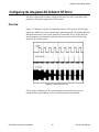
Chapter 5: Communications Configuring Serial Ports The serial communications parameters can be set using the front panel interface. Refer to Chapter 6: User Interface Reference to set the serial parameters. Serial formats allowed for communications include 8N1, 8N2, 8E1, 8O1. Data is transferred bit-wise serial with the following formats: 8N1: ST D0 D1 D2 D3 D4 D5 D6 D7 SP 8N2: ST D0 D1 D2 D3 D4 D5 D6 D7 SP SP 8E1: ST D0 D1 D2 D3 D4 D5 D6 D7 EP SP 8O1: ST D0 D1 D2 D3 D4 D5 D6 D7 OP SP T→ ST = STart bit, Dx = Data bit, SP = StoP bit, EP = Even Parity bit, OP = Odd Parity bit Figure 5-1. Bit-Wise Serial Formats Message Framing and Errors This section describes the message framing of the protocol when using the serial port as the communications channel. Message Start. Messages start with a silent interval of at least 3.5 character times. This is most easily implemented as a multiple of character times at the baud rate that is being used on the network. Device Address. The first byte transmitted is the device address. Valid slave device addresses are in the range [0..247] decimal. The individual slave devices are assigned addresses in the range of [1..247]. When the slave sends its response, it places its own address in this address field of the response to let the master know which slave is responding. Address 0 is used for the broadcast address, which all slave devices recognize. This field must match the eDrive address assigned with the front panel. Select Comm Setup Rs-232 Channel ? Setup Set Address (where ? is either 0 or 1). © Northrop Grumman Corporation 45 eDrive User Manual