1
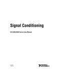
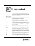
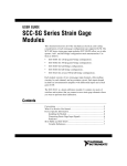
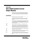
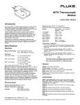
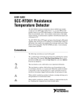
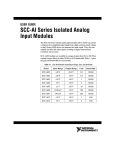
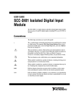
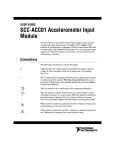
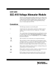
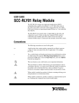
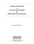
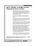
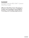
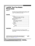
SCC Quick Start Guide
This document explains how to install, configure, and set up National
Instruments SCC modules. This document assumes you have already
installed, configured, and tested the data acquisition (DAQ) device you will
connect to the SC-2345/2350 carrier. If you have not done so, follow the
instructions in the DAQ Quick Start Guide included with the DAQ device
before continuing.
Note
This document describes how to use SCC modules with only NI-DAQmx.
Contents
Conventions ............................................................................................ 2
Measurement System Overview ............................................................. 3
Step 1. Unpack the Carrier and Modules ................................................ 4
Step 2. Verify the Components ............................................................... 5
Step 3. Cable the SC-2345/2350 Carrier to the E Series
DAQ Device......................................................................................... 6
Step 4. Set Up the SC-2345/SC-2350 Carrier......................................... 8
Procedure 1: Install the Connectors and Panelettes ......................... 8
Procedure 2: Apply I/O Panelette Labels ........................................ 10
SCC Module Installation Considerations................................................ 10
SC-2345 Carrier Considerations ...................................................... 12
SC-2350 Carrier Considerations ...................................................... 17
Step 5. Install the Modules...................................................................... 19
Step 6. Connect the Signals..................................................................... 19
SC-2350: Connecting TEDS Sensors .............................................. 20
Connecting Digital Signals (Optional) ............................................ 21
Step 7. Launch Measurement & Automation Explorer (MAX).............. 22
Step 8. Configure the SC-2345/2350 ...................................................... 22
Step 9. Configure the SCC Modules....................................................... 24
SC-2350: Configure TEDS .............................................................. 25
Step 10. Configure Channels and Tasks ................................................. 26
Configure a Task.............................................................................. 27
Configure Global Channels in NI-DAQmx ..................................... 31
Step 11. Program Your Task................................................................... 32
Getting Started Developing an Application ............................................ 33
Using Examples ............................................................................... 33
Information about Measurement Applications and Devices............ 33
Worldwide Technical Support ......................................................... 35
Conventions
The following conventions are used in this manual:
»
The » symbol leads you through nested menu items and dialog box options
to a final action. The sequence File»Page Setup»Options directs you to
pull down the File menu, select the Page Setup item, and select Options
from the last dialog box.
♦
The ♦ symbol indicates that the following text applies only to a specific
product, a specific operating system, or a specific software version.
This icon denotes a note, which alerts you to important information.
This icon denotes a caution, which advises you of precautions to take to
avoid injury, data loss, or a system crash. When this symbol is marked on
the product, refer to the Read Me First: Safety and Radio-Frequency
Interference document, shipped with the product, for precautions to take.
When symbol is marked on a product, it denotes a warning advising you to
take precautions to avoid electrical shock.
Wh
When symbol is marked on a product, it denotes a component that may be
hot. Touching this component may result in bodily injury.
bold
Bold text denotes items that you must select or click in the software, such
as menu items and dialog box options. Bold text also denotes parameter
names and information on hardware labels.
italic
Italic text denotes variables, emphasis, a cross reference, or an introduction
to a key concept.
monospace
Text in this font is used for the proper names of disk drives, paths, and
directories.
monospace italic
Italic text in this font denotes text that is a placeholder for a word or value
that you must supply.
SCC-AIXX
Refers to the SCC-AI01, SCC-AI02, SCC-AI03, SCC-AI04, SCC-AI05,
SCC-AI06, SCC-AI07, SCC-AI13, and SCC-AI14.
SCC-LPXX
Refer to the SCC-LP01, SCC-LP02, SCC-LP03, and SCC-LP04.
SCC-TC0X
Refers to the SCC-TC01 and SCC-TC02.
SCC-XX
Refers to any SCC module.
SCC-SGXX
Refers to the SCC-SG01, SCC-SG02, SCC-SG03, SCC-SG04,
and SCC-SG24.
SCC Quick Start Guide
2
ni.com
Measurement System Overview
Figure 1 depicts the measurement system overview, showing the path of
real-world physical phenomena to your measurement application.
Your Measurement Application
Application Software
LabVIEW, LabWindows/CVI, Measurement Studio, or other programming environments
Application Programming Interface (API)
NI-DAQmx, Traditional NI-DAQ, NI-SWITCH, or other API
Configuration
Measurement & Automation
Explorer (MAX)
Driver Engines
NI-DAQmx, Traditional NI-DAQ, NI-VISA
Data Acquisition and Modular Instrumentation
ON
STANDB
Y
6
7
8
PCI
PXI
PCMCIA
Signal Conditioning
®
345
SC-2
SCX
MAINFR
I
AME
SCXI
PXI/SCXI Combination
SCC
Sensors and Transducers
+
V
–
+
–
+
HV
–
+
mV
–
Real-World Signals and Physical Phenomena
Figure 1. Measurement System Overview
Sensors and transducers detect physical phenomena. Signal conditioning
components condition physical phenomena so that the measurement device
can receive the data. The computer receives the data through the
measurement device. Software controls the measurement system, telling
the measurement device when and from which channels to acquire or
generate data. Software also takes the raw data, analyzes it, and presents it
in a form you can understand, such as a graph, chart, or file for a report.
© National Instruments Corporation
3
SCC Quick Start Guide
NI measurement devices and application software are packaged with
NI-DAQ driver software to program all the features of your
NI measurement device such as configuring, acquiring, and generating data
from and sending data to NI measurement devices. Using NI-DAQ saves
you from having to write these programs yourself. Application software,
such as LabVIEW, LabWindows™/CVI™, and Measurement Studio, sends
commands to the driver, such as acquire and return a thermocouple reading,
and then displays and analyzes the data acquired.
You can use the NI-DAQ driver from NI application software or from any
programming environment that supports calling dynamic link libraries
(DLLs) through ANSI C interfaces. Regardless of the programming
environment, your DAQ application uses NI-DAQ, as shown in Figure 1.
If you have not installed, configured, and tested your DAQ device and
NI-DAQ software according to the instructions in the DAQ Quick Start
Guide, do so now.
Step 1. Unpack the Carrier and Modules
The SCC modules are shipped in an antistatic package to prevent
electrostatic damage (ESD) to the modules. ESD can damage several
components on the modules.
Caution
Never touch the exposed pins of connectors.
To avoid such damage in handling the modules, take the following
precautions:
•
Ground yourself using a grounding strap or by touching a grounded
object.
•
Touch the antistatic package to a metal part of the computer chassis
before removing the modules from the packages.
Remove the modules from the package and inspect the modules for loose
components or any sign of damage. Notify NI if the modules appear
damaged in any way. Do not install damaged modules into the carrier.
Store the SCC modules in the antistatic envelope when not in use.
For safety and compliance information, refer to the device documentation
packaged with your device, or on the NI-DAQ 7.x Device Documentation
CD in the NI-DAQ software kit or at ni.com/support. After you install
the Device Document Browser, device documents are accessible from
Start»Programs»National Instruments»NI-DAQ»Browse Device
Documentation.
SCC Quick Start Guide
4
ni.com
Step 2. Verify the Components
Make sure you have the following SCC system components.
Po
ssi
ble
(Col
or
SC
C Co
ates
nfig
strip
indic
e on
ura
SCC
tion
s
)
SC
Re -2345
fer
enc Quick
e
P/N
1841 Lab
14A el
-01
Row
A
68
Pos Ter
ition min
al Bloc
E Seri
es k Def
Pin
Num initi
Row berson
B
and
Nam
es
Row
C
X
XX
X
CSC
1
1
2
2
3
SCC Module
Power Module
5
4
3
4
SCC Carrier
Shielded Cable
5
6
6
DAQ Device
Personal Computer
In addition, you need the following items:
❑ Hardware and Documentation
–
68-pin E Series DAQ device and documentation
–
68-pin cable
–
SC-2345/2350 carrier and SC-2345/2350 User Manual
–
One or more SCC modules and user guide
❑ Software and Documentation
–
NI-DAQ 7.2 or later software and documentation
–
One of the following software packages for development:
•
LabVIEW
•
LabWindows/CVI
•
Visual C++
•
Visual Basic
❑ Other Tools
–
1/8 in. flathead screwdriver
–
Numbers 1 and 2 Phillips screwdrivers
–
Wire insulation strippers
To install NI-DAQmx, refer to the DAQ Quick Start Guide, which is
available for download at ni.com/manuals. To install the SC-2345/2350
carrier, refer to the SC-2345/2350 User Manual.
© National Instruments Corporation
5
SCC Quick Start Guide
Step 3. Cable the SC-2345/2350 Carrier to the E Series
DAQ Device
Caution Refer to the Read Me First: Safety and Radio-Frequency Interference document
before removing equipment covers or connecting/disconnecting any signal wires.
The E Series DAQ device should already be installed in your computer.
Refer to the E Series DAQ device user manual for installation instructions.
General Purpose
Counter/Timer
Channel 1
General Purpose
Counter/Timer
Channel 0
Digital I/O
or 1st Stage
of a Dual Stage
AI Configuration
Digital I/O
or 1st Stage
of a Dual Stage
AI Configuration
Connect the SC-2345/2350 carrier to the E Series DAQ device with a
68-pin shielded cable. Use connector J24 on the SC-2345/2350 carrier.
Refer to Figure 2 for the location of connector J24.
1
1
Connector J24
2
Analog Output
DAC 1
Analog Output
DAC 0
Single Stage AI
or 2nd Stage
of a Dual Stage
AI Configuration
Single Stage AI
or 2nd Stage
of a Dual Stage
AI Configuration
3
Power LEDs
2
3
SC-2345 Carrier
Figure 2. Connector J24 Location
The chassis ground terminal on the SC-2345/2350 carrier and the
electromagnetic interference (EMI) gasket attached to the strain relief of
the SC-2345 connector block are for grounding a floating source (1 mA
maximum). Do not use these terminals as safety earth grounds. For more
information about the SC-2345/2350 carrier, refer to the SC-2345/2350
User Manual.
Figure 3 shows the SC-2345 carrier with the signal wires connected.
Figures 4 and 5 show the two types of cabling on the SC-2345 with
configurable connectors.
SCC Quick Start Guide
6
ni.com
3
Po
ssib
le SC
(Co
lor
ind C C
ica
tes onfig
stripe ur
on atio
SC
C) ns
SC
Ref -234
eren 5 Q
uick
P/N ce
1841 Labe
14
l
A-0
1
Row
A
68
Po Term
siti
on ina
E Se l Blo
ries ck
Pin De
Nu finitio
mb
Row ers n
B
and
Na
me
s
Row
C
2
X
XX
SC
1
C- X
X
XX
SC
C
C -X
SC
XX
-XX
4
5
10
6
9
1
2
3
4
Screw Terminals
SCC Modules
Cover Screws
68-Pin Shielded Cable
5
6
7
8
8
7
Quick Reference Label
SCC-PWRXX
SCC Connector Block Socket
Screw Terminal Block
9 Top Strain-Relief Bar
10 Top Strain-Relief Screws
Figure 3. SC-2345 Carrier Installation Diagram
11
10
9
8
1
7
2
SC
C- X
X
XX
C- X
X
XX
SC
SC
XX
X
C- X
XX
CH
C
SC
1
CH
6
-XX
2
3
5
4
1
2
3
4
68-Pin Shielded Cable
Strain-Relief Panelette
SCC Modules
SCC Connector Block Socket
5
6
7
8
BNC Panelette
Power LEDs
SCC-PWRXX
Screw Terminals
9 Screw Terminal Block
10 Top Cover
11 Cover Screws
Figure 4. SC-2345 with Configurable Connectors (Rear Cabled) Installation Diagram
© National Instruments Corporation
7
SCC Quick Start Guide
1
2
3
4
6
SC
C- X
XX
X
X
X
CH
SC
1
11
XX
XX
CH
C- X
C- X
C- X
SC
SC
5
XX
X
7
2
10
9
8
1
2
3
4
Cover Screws
Top Cover
Screw Terminals
SCC Modules
5
6
7
8
Strain-Relief Panelette
Screw Terminal Block
68-Pin Shielded Cable
Power LEDs
9 SCC-PWRXX
10 BNC Panelette
11 SCC Connector Block Socket
Figure 5. SC-2345 with Configurable Connectors (Side Cabled) Installation Diagram
Step 4. Set Up the SC-2345/SC-2350 Carrier
The following section describes functionality common to both the SC-2345
and the SC-2350 carriers.
Procedure 1: Install the Connectors and Panelettes
If you have selected an SC carrier with configurable connectors, install the
connector and interface panelettes. Some panelettes occupy more than one
panelette slot. Table 1 lists the panelette specifications.
Table 1. Panelette Options
Connectors/Units
per Panelette
Slot Width
J- or K-type
2
1
Uncompensated
2
1
J- or K-type
1
1
Uncompensated
1
1
BNC connector
2
1
Panelette
Description
Minithermocouple jack
Thermocouple jack
BNC
SCC Quick Start Guide
8
ni.com
Table 1. Panelette Options (Continued)
Panelette
Description
Connectors/Units
per Panelette
Slot Width
SMB
SMB connector
4
1
Banana jack
Banana jack
2
1
2-pin female
2
1
4-, 6-pin female
1
1
2-, 4-, 6-pin female
1
1
Single (male)
1
2
Single (female)
1
2
Dual (male)
2
3
Dual (female)
2
3
Momentary switch
On – off
2
1
Toggle switch
(on – off – on)
2
1
Rocker switch
(on – off – on)
1
1
LED
Red, Green, Yellow, and Orange LEDs
4
1
Potentiometer
1 turn, 10
1
1
Strain relief
Small strain relief
1
2
Blank
Filler panel
—
—
LEMO (B-Series)
MIL-Spec
9-pin D-sub
Complete the following steps to install the I/O panelettes:
1.
Remove the blank panel before installing any I/O panelettes on the rear
of the SC-2345/2350 with configurable connectors.
2.
Place the lower edge of the I/O panelette in the groove at the bottom of
the enclosure opening.
3.
Tilt the panelette top back into the enclosure.
4.
Secure the panelette with either one, two, or three (depending on the
type of I/O panelette) M2.5 × 6 panhead screws that are included with
the panelette.
You can install a blank panelette into any unused panelette opening.
Connect the lead wires from the panelette to the screw terminals of the SCC
modules or to the 42-pin screw terminal block inside the SC-2345/2350
carrier.
© National Instruments Corporation
9
SCC Quick Start Guide
Procedure 2: Apply I/O Panelette Labels
The SC-2345 with Configurable Connectors and the SC-2350 are shipped
with a sheet of labels to apply to the I/O panelettes as shown in Figure 6.
2
1
1
I/O Panelette
2
Labels
Figure 6. Installing I/O Panelette Labels
The label sheet has both preprinted labels and blank labels you can
customize to your application. You can use two labels on single-width
I/O panelettes and three or more labels on wider panelettes.
SCC Module Installation Considerations
SCC modules are required for connecting to the analog inputs or analog
outputs of the E Series DAQ device. You do not need to use SCC modules
to connect to the CTR and P0. signals of the DAQ device, which are
accessible from the SC-2345 carrier. Refer to the SC-2345/2350 User
Manual for more information.
Each SCC module has a lengthwise color stripe label on the top, as
illustrated in Figure 7, that indicates the module type and function
classification of the module and displays a corresponding icon.
X
XX
SC
3
X
C-
2
1
1
2
SCC Screw-Terminal Receptacle
Label Color Stripe
3
SCC Module Name
Figure 7. SCC Module
For more information about SCC module types, accompanying icons, label
color, and measurement types, refer to Table 2.
SCC Quick Start Guide
10
ni.com
Table 2. SCC Modules: Icon, Label Color and Measurement Type
SCC Module
Icon
Label Color
Measurement Type
Blue
Analog Input
SCC_AIXX
Blue
Analog Input
SCC-A10
Blue
Analog Input
SCC-CI20
Blue
Analog Input
Blue
Analog Input
Blue
Analog Input
Blue
Analog Input
Blue
Analog Input
Blue
Analog Input
N/A
Analog Input, Analog
Output, Digital,
GPCTR
SCC-DI01
Green
Digital
SCC-DO01
Green
Digital
SCC-ACC01
ACC
INPUT
IIN
VOUT
SCC-FV01
0–100Hz
SCC-LPXX
Hz
SCC-RTD01
RTD
SCC-SG
Refer to the SCC-SG Series Strain Gage Modules User
Guide.
SCC-TC0X
TC
SCC-FT01
© National Instruments Corporation
IN
OUT
11
SCC Quick Start Guide
Table 2. SCC Modules: Icon, Label Color and Measurement Type (Continued)
SCC Module
Icon
SCC-RLY01
3)
Measurement Type
Green
Digital
Red
Analog Output
Red
Analog Output
N.O.
COM
N.C.
2)
1)
SCC-CO20
Label Color
0–20mA
ISO
SCC-AO10
3)
2)
+
–
1)
±10V
ISO
The SC-2345 carrier and the SC-2350 carrier each have different
functionality and SCC module configurations. The following sections
cover carrier-specific information relative to SCC module installation.
SC-2345 Carrier Considerations
The following section provides information specific to the SC-2345 carrier.
Quick Reference Label
Affix the Quick Reference Label to the inside cover of the SC-2345.
This label, shown in Figure 8, shows the possible configurations of SCC
modules. The Quick Reference Label also lists the location of each signal
on the SC-2345 carrier modules. The numbers on the label correspond to
the terminal numbers on the 68-pin E Series connector.
Dual-Stage
Analog Input
J1-8
J9-16
2nd Stage
Analog Input
Socket
1st Stage
Analog Input
Socket
Single-Stage
Analog Input
and/or Digital I/O
J1-8
J9-16
Analog Input
Single Stage
Socket (Optional)
Digital I/O
Socket (Optional)
Analog Output
and/or
GPCTR
J17-18
J19-20
Analog Output
Socket*
(Optional)
General-Purpose
Counter/Timer
Socket (Optional)
Legend:
Blue
Green
Red
Yellow
*Analog Output is not available
on AI E Series boards
Figure 8. SCC Module Configurations by Socket,
Function Classification, and Color Code
SCC Quick Start Guide
12
ni.com
SC-2345 Carrier Diagrams
Figures 9, 10, and 11 show diagrams of the three types of SC-2345 carriers.
Single Stage AI
or 2nd Stage
of a Dual Stage
AI Configuration
Single Stage AI
or 2nd Stage
of a Dual Stage
AI Configuration
Single Stage AI
or 2nd Stage
of a Dual Stage
AI Configuration
Single Stage AI
or 2nd Stage
of a Dual Stage
AI Configuration
Single Stage AI
or 2nd Stage
of a Dual Stage
AI Configuration
Single Stage AI
or 2nd Stage
of a Dual Stage
AI Configuration
Analog Output
DAC 0
Analog Output
DAC 1
Digital I/O
or 1st Stage
of a Dual Stage
AI Configuration
Digital I/O
or 1st Stage
of a Dual Stage
AI Configuration
Digital I/O
or 1st Stage
of a Dual Stage
AI Configuration
Digital I/O
or 1st Stage
of a Dual Stage
AI Configuration
Digital I/O
or 1st Stage
of a Dual Stage
AI Configuration
Digital I/O
or 1st Stage
of a Dual Stage
AI Configuration
Digital I/O
or 1st Stage
of a Dual Stage
AI Configuration
General Purpose
Counter/Timer
Channel 0
General Purpose
Counter/Timer
Channel 1
9
Single Stage AI
or 2nd Stage
of a Dual Stage
AI Configuration
1
Digital I/O
or 1st Stage
of a Dual Stage
AI Configuration
8
Single Stage AI
or 2nd Stage
of a Dual Stage
AI Configuration
Digital I/O
or 1st Stage
of a Dual Stage
AI Configuration
Digital I/O
or 1st Stage
of a Dual Stage
AI Configuration
Digital I/O
or 1st Stage
of a Dual Stage
AI Configuration
Digital I/O
or 1st Stage
of a Dual Stage
AI Configuration
Digital I/O
or 1st Stage
of a Dual Stage
AI Configuration
Digital I/O
or 1st Stage
of a Dual Stage
AI Configuration
Digital I/O
or 1st Stage
of a Dual Stage
AI Configuration
Digital I/O
or 1st Stage
of a Dual Stage
AI Configuration
General Purpose
Counter/Timer
Channel 0
General Purpose
Counter/Timer
Channel 1
Single Stage AI
or 2nd Stage
of a Dual Stage
AI Configuration
Single Stage AI
or 2nd Stage
of a Dual Stage
AI Configuration
Single Stage AI
or 2nd Stage
of a Dual Stage
AI Configuration
Single Stage AI
or 2nd Stage
of a Dual Stage
AI Configuration
Single Stage AI
or 2nd Stage
of a Dual Stage
AI Configuration
Single Stage AI
or 2nd Stage
of a Dual Stage
AI Configuration
Single Stage AI
or 2nd Stage
of a Dual Stage
AI Configuration
Analog Output
DAC 0
Single Stage AI
or 2nd Stage
of a Dual Stage
AI Configuration
Analog Output
DAC 1
3
6
3
7
2
10
11
SCC Quick Start Guide
13
© National Instruments Corporation
2
1
9 SCC Socket Reference Designator
10 SCC Socket
Screw-Terminal Block
J25
J24
SCC Key Slot
5
6
7
8
Power LEDs
J21
Serial Number
Assembly Number
1
2
3
4
10
4
8
5
9 Screw-Terminal Block
10 Grounding Terminal Lug
11 Assembly Number
J24
J25
J21
Power LEDs
5
6
7
8
SCC Socket
SCC Socket Reference Designator
SCC Key Slot
Serial Number
1
2
3
4
5
4
Figure 9. SC-2345 Carrier Diagram
7
6
9
Figure 10. SC-2345 with Configurable Connectors (Rear Cabled) Diagram
General Purpose
Counter/Timer
Channel 1
5
General Purpose
Counter/Timer
Channel 0
Digital I/O
or 1st Stage
of a Dual Stage
AI Configuration
Digital I/O
or 1st Stage
of a Dual Stage
AI Configuration
Digital I/O
or 1st Stage
of a Dual Stage
AI Configuration
Digital I/O
or 1st Stage
of a Dual Stage
AI Configuration
Digital I/O
or 1st Stage
of a Dual Stage
AI Configuration
Digital I/O
or 1st Stage
of a Dual Stage
AI Configuration
Digital I/O
or 1st Stage
of a Dual Stage
AI Configuration
Digital I/O
or 1st Stage
of a Dual Stage
AI Configuration
4
6
3
7
Analog Output
DAC 1
Analog Output
DAC 0
Single Stage AI
or 2nd Stage
of a Dual Stage
AI Configuration
Single Stage AI
or 2nd Stage
of a Dual Stage
AI Configuration
Single Stage AI
or 2nd Stage
of a Dual Stage
AI Configuration
Single Stage AI
or 2nd Stage
of a Dual Stage
AI Configuration
Single Stage AI
or 2nd Stage
of a Dual Stage
AI Configuration
Single Stage AI
or 2nd Stage
of a Dual Stage
AI Configuration
1
Single Stage AI
or 2nd Stage
of a Dual Stage
AI Configuration
Single Stage AI
or 2nd Stage
of a Dual Stage
AI Configuration
2
8
9
10
1
2
3
4
SCC Socket Reference Designator
SCC Socket
SCC Key Slot
Screw-Terminal Block
5
6
7
8
Assembly Number
Serial Number
J24
Power LEDs
9 J25
10 J21
Figure 11. SC-2345 with Configurable Connectors (Side Cabled) Carrier Diagram
Analog Input SCC Modules
Analog input sockets are arranged in aligned pairs so that sockets J(X+1)
and J(X+9) form a pair, for all X 0 to 7. The SC-2345 routes analog input
signals to E Series DAQ device channels AI (X) and AI (X+8). For
example, if you plug an SCC-A10 voltage attenuator module into socket J4,
the signal on one channel is routed to AI 3 and the signal on the other
channel is routed to AI 11. Refer to ni.com/info and enter rdtntg in the
info code field to confirm signal names in the NI-DAQ C to NI-DAQmx
Terminal Names Translation Guide.
Single-Stage Analog Input Conditioning
For single-stage analog input conditioning, plug the SCC module into any
socket J1 to J8 and connect the I/O signals to it. In a single-stage analog
input SCC configuration, you connect your external signal to an SCC
module that conditions the signal and passes it to the DAQ device.
SCC Quick Start Guide
14
ni.com
Dual-Stage Analog Input Conditioning
For dual-stage analog input conditioning, plug the first-stage SCC module
into any socket J(X+9) and plug the second-stage SCC module into the
corresponding paired socket, J(X+1). Connect the input signals to the
first-stage SCC module, and none to the second-stage SCC. The SC-2345
connects the output signals of the first-stage SCC modules to the inputs of
the second-stage SCC modules and routes the outputs of the second-stage
modules to E Series DAQ device channels AI (X) and AI (X+8). An
example of dual-stage conditioning is a voltage attenuator SCC module
followed by a lowpass filter SCC module. Figure 12 shows how to install
analog input modules on the SC-2345 carrier.
C
6
SC
2
-X
SC
C
XX
-X
X
XX
X
Sometimes, you can cascade two analog input SCC modules together on a
single analog input channel to form a dual-stage configuration. The first
stage of a dual-stage analog input configuration can be in sockets J9–J16.
The second stage of a dual-stage analog input configuration can be in
sockets J1–J8.
2
3
3
3
2
1
3
2
1
SC
C
-X
XX
X
5
4
1
7
3
2
1
A
B
A Single-Stage Analog Input
B Dual-Stage Analog Input
1 J9 Connector Block (SCC
Module Not Installed)
2
3
4
5
Analog SCC Plugged into J1
SC-2345 Carrier
Analog SCC Plugged into J9
First Stage
6
7
Second Stage
Do Not Connect Any Signals to
the Second-Stage SCC
Figure 12. Single- and Dual-Stage Analog Input SCC Configuration
for SC-2345 Connector Block Socket
Table 3 shows all the analog input SCC modules that can be configured
on the SC-2345 carrier and whether the modules support single-stage,
dual-stage, or both configurations.
© National Instruments Corporation
15
SCC Quick Start Guide
Table 3. SCC Modules and Dual-Stage Compatibility
Single-Stage Analog
Input (J1–J8)
First Stage of Dual-Stage
Analog Input (J9–J16)
Second Stage of Dual-Stage
Analog Input (J1–J8)
SCC-AIXX
Yes
Yes
No
SCC-A10
Yes
Yes
No
SCC-RTD01
Yes
Yes
No
SCC-CI20
Yes
Yes
No
SCC-ACC01
Yes
Yes
No
SCC-TC0X
Yes
Yes
No
SCC-FV01
Yes
No
Yes
SCC-LPXX
Yes
Yes
Yes
SCC-FT01
Yes
Yes
Yes
SCC-SGXX
Yes
Yes
No
SCC Modules
Digital SCC Modules
Sockets J9 to J16 work for digital SCC modules as well as for analog
inputs. Plug a digital SCC module into any socket J(X+9), where X is 0 to 7,
and connect the P0. signal to the module. The SC-2345 routes the P0. signal
to E Series DAQ device channel P0.(X). Figure 13 illustrates a digital
module with an analog input module.
XX
4
X
XX
C-X
-XX
C
SC
1
3
2
1
SC
3
3
2
1
2
4
1
2
SC-2345 Carrier
Input Signals
3
4
Digital SCC Plugged into J9
Analog SCC Plugged into J1
Figure 13. Single-Stage Analog Input and DIO SCC Configuration
for SC-2345 Connector Block Socket
SCC Quick Start Guide
16
ni.com
Analog Output SCC Modules
You can plug analog output SCC modules into the SC-2345 using sockets
J17 and J18. Each socket connects to both analog output channels of the
E Series DAQ device, although each is identified on the SC-2345 as being
for either channel 0 or channel 1. These designations indicate the primary
analog output channel each socket uses. Analog output channel 0 is the
primary channel for socket J17. Analog output channel 1 is the primary
channel for socket J18.
GPCTR SCC Modules
You can build GPCTR circuitry onto the SCC-FT01 feedthrough module.
Plug the custom GPCTR SCC module into socket J19 or J20 of the
SC-2345. Socket J19 connects to E Series GPCTR channel 0. Socket J20
connects to E Series GPCTR channel 1.
SC-2350 Carrier Considerations
The SC-2350 has integrated software support for Transducer Electronic
Data Sheet (TEDS) sensors. For more information about using TEDS with
SCC modules, refer to the SC-2345/2350 User Manual.
The SC-2350 carrier has 16 channels of analog input sockets, J1 to J8, in
one row of eight sockets. You can use any analog input SCC module in a
single-stage analog input configuration. In addition, it contains two analog
output sockets, J17 and J18, for outputting up to two channels of data with
the appropriate SCC modules inserted.
The SC-2350 does not support dual-stage configuration or digital signals.
Therefore you cannot use all SCC modules with the SC-2350 carrier.
For information about the SC-2350 carrier and SCC module compatibility,
refer to Table 4.
Table 4. SC-2350 Carrier and SCC Module Compatibility
© National Instruments Corporation
SCC Module
Plugs into the SC-2350 Carrier
SCC-ACC01
Yes
SCC-AIXX
Yes
SCC-A10
Yes
SCC-CI20
Yes
SCC-FV01
Yes
SCC-LPXX
Yes
SCC-RTD01
Yes
SCC-SGXX
Yes
17
SCC Quick Start Guide
Table 4. SC-2350 Carrier and SCC Module Compatibility (Continued)
SCC Module
Plugs into the SC-2350 Carrier
SCC-TC0X
Yes
SCC-FT01
Yes
SCC-DI01
No
SCC-DO01
No
SCC-RLY01
No
SCC-CO20
Yes
SCC-AO10
Yes
SC-2350 Carrier Diagram
Figure 14 shows the locations of the SCC module sockets, screw-terminal
block, and other parts on the SC-2350 carrier.
4
©
5
COPYRIGHT 2003
6
7
MADE IN U.S.A.
N114
J33
J30
J27
DATA+ 0/8 DATA+ 1/9
RETURN 0/8 RETURN 1/9
J31
J29
J28
J34
DATA+ 2/10
DATA+ 3/11
DATA+ 4/12
DATA+ 5/13
RETURN 2/10 RETURN 3/11
RETURN 4/12 RETURN 5/13
TEDS CONNECTIONS FOR ANALOG INPUT
J26
J32
DATA+ 6/14
DATA+ 7/15
RETURN 6/14 RETURN 7/15
3
DATA+ 0/1
RETURN 0/1
TEDS ANALOG
OUTPUT
8
2
Analog Input
AI 0/8
Analog Input
AI 1/9
Analog Input
AI 2/10
Analog Input
AI 3/11
Analog Input
AI 4/12
Analog Input
AI 5/13
Analog Input
AI 6/14
Analog Input
AI 7/15
Analog Output
AO 0
Analog Output
AO 1
1
AI 0/8
AI 1/9
AI 2/10
AI 3/11
AI 4/12
AI 5/13
AI 6/14
AI 7/15
AO 0
AO 1
J21
9
10
11
1
2
3
4
SCC Socket Reference Designator
SCC Socket
SCC Key Slot
50-Pin Test Header
5
6
7
8
Serial Number
Assembly Number
Screw-Terminal Block
J24
9 Power LEDs
10 J25
11 J21
Figure 14. SC-2350 Carrier with TEDS
SCC Quick Start Guide
18
ni.com
Step 5. Install the Modules
When properly oriented, SCC modules plug easily onto the connector
block socket. Never force an SCC module onto the socket.
To install the SCC modules on the connector block sockets of the
SC-2345/2350 carrier, complete the following steps:
1.
Remove the cover screws on either side of the top cover with a
Number 1 Phillips screwdriver. Open or remove the top cover.
2.
If your carrier is equipped with a strain relief module, loosen the
strain-relief screws with a Number 2 Phillips screwdriver and slide the
signal wires through the strain-relief opening. If you are connecting
multiple signals, you may need to remove the top strain-relief bar.
3.
Plug the SCC modules onto the appropriate connector block sockets.
Refer to the Device-Specific Information section of the SCC-XX
module user guides for the specific socket requirements of the SCC
modules.
Step 6. Connect the Signals
Always refer to the specifications in your SCC-XX module user guide before
connecting signals. Exceeding specified module ratings can create a shock or fire hazard
and damage any or all of the devices connected to the module.
Caution
Refer to ni.com/info and enter rdtntg in the info code field to confirm
signal names in the NI-DAQ C to NI-DAQmx Terminal Names Translation
Guide.
To connect the panelette wires to the SCC module screw terminals and the
screw-terminal block in the SC-2345/2350 carrier modules that use
panelettes, complete the following steps:
1.
Remove power from the signal lines.
2.
Strip 7 mm (0.25 in.) of insulation from the ends of the signal wires.
3.
Insert the wires into the screw terminals.
The SCC-XX module has a fixed screw-terminal receptacle and a
removable screw-terminal block, as shown in Figure 15.
© National Instruments Corporation
19
SCC Quick Start Guide
1
4
3
2
1
2
1
SCC Screw-Terminal Receptacle
2
Removable Screw-Terminal Block
Figure 15. SCC-XX Two-Part Screw-Terminal System
4.
Tighten the screws to 0.5 to 0.6 N · m (4.4 to 5.3 lb – in.) of torque.
5.
Reinstall the strain-relief bar if necessary, and tighten the strain-relief
screws.
6.
Close or replace the top cover.
7.
Reinsert and tighten the cover screws to ensure proper shielding.
For complete signal-connection information, refer to the SCC-XX module
user guide. For more information about using the SC-2345, refer to the
SC-2345/2350 User Manual.
SC-2350: Connecting TEDS Sensors
If you are using an IEEE P1451.4 TEDS-compatible smart sensor,
complete the following steps to connect the TEDS DATA and RETURN
signals. Refer to Figure 16 when completing the following steps.
1.
Connect the DATA signal to the DATA+ screw terminal on the TEDS
screw terminal.
2.
Connect the RETURN signal to the RETURN screw terminal on the
TEDS screw terminal.
0
1
1
2
J27
3
4
DATA+ 2/10
RETURN 2/10
1
DATA+ 2
2
DATA+ 10
3
RETURN 10
4
RETURN 2
Figure 16. TEDS DATA+ and RETURN Connections
SCC Quick Start Guide
20
ni.com
Figure 17 shows the SC-2350 carrier with the SCC modules installed.
1
2
3
4
5
11
8
10
6
7
9
1
2
3
4
5
6
Cover Screws
Screw Terminal Block
TEDS Screw Terminal
SCC Module—Analog Output
SCC-PWRXX
D-Sub Panelette
7
8
9
10
11
SCC Modules—Analog Input
Connector Block Sockets
TEDS Screw Terminal: RETURN Screw Terminal
TEDS Screw Terminal: DATA+ Screw Terminal
Strain-Relief Panelette
Figure 17. SC-2350 Carrier Installation Diagram
Connecting Digital Signals (Optional)
The SC-2345/2350 has a 42-position, triple-row screw-terminal block for
connecting to E Series DAQ device digital signals. The terminal block
can connect to P0.<0..7>, +5 V, D GND, PFI <0..9>, CTR <0,1> GATE,
CTR <0,1> OUT, CTR <0,1> SOURCE, AI SENSE, FREQ OUT,
EXTSTROBE, and AI HOLD COMP. The SC-2345 Quick Reference
Label identifies the location of each signal on the terminal rows A to C.
The terminal label numbers correspond to the pin number location of each
signal on the 68-pin E Series connector. Refer to the E Series DAQ device
user manual for more information about this connector.
© National Instruments Corporation
21
SCC Quick Start Guide
Figure 18 shows the locations of the digital signals on the terminal block.
A
NC
NC
FREQ OUT
CTR 0 OUT
PFI 8/CTR 0 SRC
PFI 6/AO START
PFI 4/CTR 1 GATE
PFI 2/AI CONV
PFI 0/AI START
(+) 5 V
P0.6
P0.4
P0.2
P0.0
1
2
37
5
41
43
11
14
16
19
49
52
B
NC
D GND
D GND
D GND
D GND
D GND
D GND
D GND
D GND
D GND
D GND
D GND
D GND
D GND
35
4
36
39
7
9
44
12
13
15
50
18
53
C
NC
AI SENSE
EXT STROBE
CTR 1 OUT
PFI 9/CTR 0 GATE
PFI 7/AI SAMP
PFI 5/AO SAMP
PFI 3/CTR 1 SRC
PFI 1/REF TRIG
AI HOLD COMP
P0.7
P0.5
P0.3
P0.1
62
45
40
3
38
6
42
10
46
48
51
47
17
Figure 18. Terminal Block I/O Connector Pin Assignments
♦
SC-2345 connector block (The following does not apply to the SC-2345
with configurable connectors or to the SC-2350.)
A metallized nylon knit EMI gasket is attached to the strain-relief bars of
the SC-2345 connector block. Using shielded cables to connect the signals
allows you to ground the shielded signal cables. Stripping the insulation
away from the shield of the cables forms a chassis ground connection at the
strain-relief bar. To avoid adding noise to the signal, ground the cable shield
only at one end. For complete signal connection information, refer to the
SCC-XX module user guide. For more information about using the
SC-2345, refer to the SC-2345/2350 User Manual.
Step 7. Launch Measurement & Automation Explorer (MAX)
Double-click the Measurement & Automation icon on the desktop to
open MAX.
Step 8. Configure the SC-2345/2350
You can use the SC-2350 only in NI-DAQmx; you can use the SC-2345 in
either NI-DAQmx or Traditional NI-DAQ.
1.
SCC Quick Start Guide
Open Devices and Interfaces. If your device does not automatically
appear, press <F5> to refresh the view in MAX. If the device is still not
recognized, refer to ni.com/support/install for troubleshooting
information.
22
ni.com
2.
Right-click Devices and Interfaces and select Create New.
Figure 19. Create New in Devices and Interfaces
3.
Select either the SC-2345 or SC-2350 from the Create New window.
4.
Select the carrier under NI-DAQmx Device»NI-DAQmx
SCC Connector Block. The configuration window opens as shown in
Figures 20 and 21.
Figure 20. SC-2345 Connector Block Configuration Window
© National Instruments Corporation
23
SCC Quick Start Guide
Figure 21. SC-2350 Configuration Window
Configuring the SCC system using MAX automatically sets the E Series
DAQ device analog input mode to NRSE.
Note
Step 9. Configure the SCC Modules
Complete the following steps to configure the SCC modules in
NI-DAQmx:
SCC Quick Start Guide
1.
Specify the SCC Carrier Type. The location of the SCC sockets
change depending on the SCC carrier type.
2.
Select the DAQ Device that is connected to the SC-2345/2350 carrier.
3.
Type the SCC Connector Block ID. The default value is SCC1.
24
ni.com
4.
In the J21 drop-down list next to Power, select the correct
SC-2345/2350 power configuration. The SC-2345/2350 shielded
carrier has one of the following power modules factory-installed in
socket J21:
•
SCC-PWR01—5 VDC from the E Series DAQ device or an
external supply
•
SCC-PWR02—Universal AC external supply
•
SCC-PWR03—7 to 42 VDC external supply module (power
supply not included)
For more information about how to select the power option for the
SCC 2345/2350 carrier module, refer to the SC-2345/2350 User
Manual.
5.
For each SCC module physically installed in the SC-2345/2350
carrier, add a corresponding entry in the SC-2345/2350 configuration
window. To add the SCC, click the Socket drop-down list and select the
correct module.
6.
If the module name does not appear in the list, either the module is not
allowed in that location or you do not have the current version of
NI-DAQ. If you do not have the current version of NI-DAQ, download
it from ni.com/downloads.
7.
Click OK after completing all SCC entries to complete the
configuration process.
For more information, refer to the SC-2345/2350 User Manual.
SC-2350: Configure TEDS
If you are using a TEDS sensor, complete the following steps to configure
the TEDS sensor in MAX:
1.
If MAX is not already open, double-click the MAX icon.
2.
Under NI-DAQmx Devices, right-click SC-2350 and select
Properties. The SC-2350 Configuration window opens. Leave the
DAQ Device and the SCC Connector Block ID as the defaults.
3.
Select the SCC module from the appropriate drop-down list (Jx).
4.
The LED to the right of your module should appear bright green if your
sensor is connected. If the LED is not bright green, connect your sensor
now and click Scan for TEDS. Click OK.
5.
Expand the SC-2350 and the module connected to the TEDS sensor.
6.
Click the TEDS sensor, and the TEDS sensor’s specifications appear
in the right pane of the window.
7.
Verify that your TEDS data has imported correctly. If your data has not
imported correctly, repeat steps 2 through 7.
© National Instruments Corporation
25
SCC Quick Start Guide
Step 10. Configure Channels and Tasks
This step applies only if you are programming your device using NI-DAQ
or NI application software.
A physical channel is a terminal or pin at which you can measure or
generate an analog or digital signal. A virtual channel is a collection
of settings that include a name, a physical channel, input terminal
connections, the type of measurement or generation, and scaling
information. In NI-DAQmx, virtual channels are integral to every
measurement. In Traditional NI-DAQ, configuring virtual channels is
an optional way to record which channels are being used for different
measurements. Figure 22 depicts how to configure channels in NI-DAQmx
and Traditional NI-DAQ. If you are using a TEDS sensor, you can use only
NI-DAQmx.
Configure channels and tasks.
Use MAX to configure channels. Refer to
Measurement &Automation Explorer Help
for Traditional NI-DAQ.
Traditional
NI-DAQ
NI-DAQmx
What API are you using to
program each device?
Use the DAQ Assistant, accessible from MAX
or NI application software, to configure
channels and measurement tasks.
Refer to the DAQ Assistant Help
and Measurement & Automation
Explorer Help for NI-DAQmx.
You have installed and configured your devices.
Figure 22. Configuring Channels and Tasks in NI-DAQmx and Traditional NI-DAQ
A task, an important new concept for NI-DAQmx, is a collection of one
or more virtual channels with timing, triggering, and other properties.
Conceptually, a task represents a measurement or generation you want
to perform. You can set up and save all of the configuration information
in a task and use the task in an application.
In NI-DAQmx, you can configure virtual channels as part of a task or
separate from a task. Virtual channels created inside a task are local
channels. Virtual channels defined outside a task are global channels.
You can create global channels in MAX or in your application software
and then save them in MAX. You can use global channels in any
application or add them to a number of different tasks. If you modify a
global channel, the change affects all tasks in which you reference that
global channel. In most cases, it is simpler to use local channels.
SCC Quick Start Guide
26
ni.com
Configure a Task
When using NI-DAQmx, configure tasks with the DAQ Assistant. You
must have version 7.0 or later (7.2 for the SC-2350) of an NI application
software package to create tasks and channels with the DAQ Assistant.
•
In MAX, right-click Data Neighborhood and select Create New.
In the Create New window, select NI-DAQmx Task and click Next.
If you are using a remote system running LabVIEW Real-Time,
expand Remote Systems, find and expand your target, then right-click
Data Neighborhood and select Create New.
•
You also can open the DAQ Assistant directly within NI application
software:
–
© National Instruments Corporation
In LabVIEW and LabVIEW Real-Time, there are several ways to
open the DAQ Assistant:
•
Place the DAQ Assistant Express VI from the Express Input
palette on the block diagram, as described in Getting Started
with LabVIEW.
•
You also can place the DAQmx Task Name control on the
front panel to open the DAQ Assistant. Right-click the control
and select New Task (DAQ Assistant). Taking an
NI-DAQmx Measurement in LabVIEW has step-by-step
instructions for creating a task from the DAQmx Task Name
control and generating code based on the task. In LabVIEW,
select Help»Taking an NI-DAQmx Measurement.
–
In LabWindows/CVI, select Tools»Create/Edit DAQmx Tasks.
–
In Measurement Studio, open Visual Studio .NET and the project
in which you want to create a DAQmx task class:
1.
Select Project»Add New Item. The Add New Item dialog
box opens.
2.
In the Categories pane, select Measurement Studio»
Assistants.
3.
In the Templates pane, select DAQmx Task Class.
4.
Specify a name for the DAQmx task file and click Open.
5.
Specify whether to create a new task or a project copy of a
global task you create in MAX.
6.
Click Finish.
27
SCC Quick Start Guide
The DAQ Assistant opens. Complete the following steps to create a
new task:
1.
Select I/O type, such as analog input.
2.
Select the appropriate measurement type based on the hardware
functionality of your module. Table 5 lists the measurement types
in NI-DAQmx and how they correspond to the SCC modules.
For additional information about SCC-XX module-specific
channel/task settings, refer to the individual SCC-XX module user
guide.
Table 5. SCC Module and Corresponding NI-DAQmx Measurement Type
Recommended NI-DAQmx
Measurement Type
SCC Module
Recommended
Parameter Settings1
SCC-ACC01
Analog Input»Accelerometer
Current Excitation Value = 4 mA,
Excitation Source = Internal
Sensitivity = #
SCC-AI01
Analog Input»Voltage
Max/Min = ±42 V
SCC-AI02
Analog Input»Voltage
Max/Min = ±20 V
SCC-AI03
Analog Input»Voltage
Max/Min = ±10 V
SCC-AI04
Analog Input»Voltage
Max/Min = ±5 V
SCC-AI05
Analog Input»Voltage
Max/Min = ±1 V
SCC-AI06
Analog Input»Voltage
Max/Min = ±100 mV
SCC-AI07
Analog Input»Voltage
Max/Min = ±50 mV
SCC-AI13
Analog Input»Voltage
Max/Min = ±10 V
SCC-AI14
Analog Input»Voltage
Max/Min = ±5 V
SCC-A10
Analog Input»Voltage
Max/Min = ±100 V
SCC-AO10
Analog Output»Voltage
Max/Min = ±10 V
SCC-CI20
Analog Input»Current
Max = 20 mA, Min = 0 mA
SCC-CO20
Analog Output»Current
Max = 20 mA, Min = 0 mA
SCC-DI01
Digital Input
Use default
SCC-DO01
Digital Output
Use default
SCC-FT01
Any measurement type
Based on your application
SCC-FV01
Analog Input»Frequency
Use default
SCC-LP01
Analog Input»Voltage
Max/Min = ±10 V
SCC-LP02
Analog Input»Voltage
Max/Min = ±10 V
SCC-LP03
Analog Input»Voltage
Max/Min = ±10 V
SCC Quick Start Guide
28
ni.com
Table 5. SCC Module and Corresponding NI-DAQmx Measurement Type (Continued)
SCC Module
Recommended NI-DAQmx
Measurement Type
Recommended
Parameter Settings1
SCC-LP04
Analog Input»Voltage
Max/Min = ±10 V
SCC-RLY01
Digital Output
Use default
SCC-RTD01
Analog Input»Temperature»RTD
Current Excitation Value = 1 mA
Excitation Source = Internal
RTD Type = #
R0 = #
Resistance Configuration = #
SCC-SG01
Analog Input»Strain Gage
Strain Configuration = Quarter Bridge I
Gage Resistance = 120 Ω
Gage Factor = #
SCC-SG02
Analog Input»Strain Gage
Strain Configuration = Quarter Bridge I
Gage Resistance = 350 Ω
Gage Factor = #
SCC-SG03
Analog Input»Strain Gage
Strain Configuration = Half Bridge I
Gage Resistance = #
Gage Factor = #
Poisson Ratio = #
SCC-SG04
Analog Input»Strain Gage
Strain Configuration = Full Bridge I
Gage Resistance = #
Gage Factor = #
Analog Input»Custom Voltage
with Excitation
Max/Min = ±100 mV
Bridge Type = Full Bridge
Excitation Source = Internal
Excitation Value = 2.5 V
Analog Input»Strain Gage
Strain Configuration = Full Bridge I
Excitation Value = 10 V
Gage Resistance = #
Gage Factor = #
Analog Input»Custom Voltage
with Excitation
Max/Min = ±100 mV
Bridge Type = Full Bridge
Excitation Source = Internal
Excitation Value = 10 V
SCC-SG11
Digital Output
Use default
SCC-TC01
Analog Input»Temperature»
Thermocouple
CJC Source = Built In
Thermocouple Type = #
SCC-TC02
Analog Input»Temperature»
Thermocouple
CJC Source = Built In
Thermocouple Type = #
SCC-SG24
1 Use default value for parameters not specified in the table.
# Based upon sensor specification.
© National Instruments Corporation
29
SCC Quick Start Guide
3.
Choose the sensor to use, if applicable for that measurement. Click
Next. The DAQ Assistant window opens for the task you have
specified.
4.
Select the channels to add to the task. If your system is configured with
a TEDS-compatible sensor, click the TEDS Channels tab. Select the
physical channel(s). The DAQ Assistant imports the setting from the
sensor and creates the task. Click Next.
5.
Type the new task name. Click Finish.
Figure 23. DAQ Assistant
6.
Configure measurement-specific settings such as timing, triggering,
and scaling, if necessary.
7.
Save the task.
8.
SCC Quick Start Guide
•
If you opened the DAQ Assistant from LabVIEW or
LabWindows/CVI, click OK.
•
If you opened the DAQ Assistant from Measurement Studio,
select File»Save.
•
If you opened the DAQ Assistant from MAX, click Save Task.
Click Test. Verify your data in the window that opens. If the data is
incorrect, verify the TEDS information and the settings in the DAQ
Assistant window.
30
ni.com
Currently, you cannot use the DAQ Assistant to create a task that contains more
than one measurement type, such as voltage and temperature channels. You must do it
programmatically. Refer to ni.com/support and search on More Than One
Measurement Type in a Task for instructions.
Note
You now can use the task in an application. Refer to the DAQ Assistant
Help for more information about using a task or generating code in your
programming environment.
Configure Global Channels in NI-DAQmx
When using NI-DAQmx, configure global channels with the DAQ
Assistant.
•
In MAX, right-click Data Neighborhood and select Create New. If
you are using a remote system running LabVIEW Real-Time, expand
Remote Systems, find and expand your target, then right-click Data
Neighborhood and select Create New.
In the Create New window, select NI-DAQmx Global Channel
and click Next.
•
You also can open the DAQ Assistant directly within version 7.x
or later of LabVIEW, LabWindows/CVI, or Measurement Studio,
or LabVIEW Real-Time version 7.1:
–
In LabVIEW and LabVIEW Real-Time, use the DAQmx Global
Channel control to open the DAQ Assistant. Right-click the
control and select New Channel (DAQ Assistant).
–
In LabWindows/CVI or Measurement Studio, first you must
create a task as previously described. In the DAQ Assistant, click
Add Existing DAQmx Global Channels to add global channels
to your task. You must use MAX to create global channels.
The DAQ Assistant opens. Complete the following steps to create a new
global channel:
1.
Select an I/O type, such as analog input.
2.
Select the measurement or generation to perform.
3.
Choose the sensor to use, if applicable for that measurement. A dialog
box opens for the task you have specified.
4.
Select the channels to add to the task. You can select physical channels
from which to create local channels in the task, and add global
channels to the task.
If your system is configured with a TEDS-compatible sensor, click the
TEDS Channels tab. Select the physical channel(s). The DAQ
Assistant imports the setting from the sensor, and uses the information
to create the task. Click Next.
© National Instruments Corporation
31
SCC Quick Start Guide
5.
Type the new global channel name. Click Finish.
6.
Configure measurement-specific settings.
If one or more channels are configured for TEDS, some settings loaded
from TEDS are not editable.
7.
8.
Save the channel.
•
If you opened the DAQ Assistant from LabVIEW or
LabWindows/CVI, click OK.
•
If you opened the DAQ Assistant from Measurement Studio,
select File»Save.
•
If you opened the DAQ Assistant from MAX, click Save
Channel.
Click Test. Verify your data in the window that opens. If the data is
incorrect, verify the TEDS information and the settings in the DAQ
Assistant window.
You now can use the global channel in an application or add the global
channel to a task. Refer to the DAQ Assistant Help or application software
documentation for more information about using a channel or generating
code.
Step 11. Program Your Task
Complete the following steps to use a measurement task in LabVIEW:
1.
Open LabVIEW and select a blank VI.
2.
Place the following constant on the block diagram: NI Measurement»
DAQmx-DataAcquisition»DAQmx Task Name Constant.
3.
Select your task from the pull-down menu.
4.
Right-click the VI. Select Generate Code»Example.
5.
Run the program from the front panel.
Refer to the DAQ Assistant Help or application software documentation
for more information about using a channel or generating code for
LabWindows/CVI or Measurement Studio.
SCC Quick Start Guide
32
ni.com
Getting Started Developing an Application
Using Examples
Each API includes a collection of programming examples to help you get
started developing an application. You can modify example code and save
it in an application. You can use examples to develop a new application or
add example code to an existing application.
To locate LabVIEW and LabWindows/CVI examples, open the National
Instruments Example Finder:
•
In LabVIEW, select Help»Find Examples.
•
In LabWindows/CVI, select Help»NI Example Finder.
Measurement Studio, Visual Basic, and ANSI C examples are located as
follows:
•
•
NI-DAQmx examples for Measurement Studio-supported languages
are in the following directories:
–
MeasurementStudio\VCNET\Examples\DAQmx
–
MeasurementStudio\DotNET\Examples\DAQmx
Traditional NI-DAQ examples for Visual Basic are in the following
directories:
–
NI-DAQ\Examples\Visual Basic with Measurement
Studio directory contains a link to the ActiveX control examples
for use with Measurement Studio.
–
NI-DAQ\Examples\VBasic directory contains the examples
not associated with Measurement Studio.
•
NI-DAQmx examples for ANSI C are in the NI-DAQ\Examples\
DAQmx ANSI C directory.
•
Traditional NI-DAQ examples for ANSI C are in the NI-DAQ\
Examples\VisualC directory.
For hundreds of additional examples, refer to ni.com/zone.
Information about Measurement Applications and Devices
You can find information about your measurement applications and
devices in the following locations:
•
LabVIEW
–
© National Instruments Corporation
If you are a new user, complete Getting Started with LabVIEW
to get acquainted with LabVIEW. Select Start»Programs»
National Instruments»LabVIEW»Search the LabVIEW
Bookshelf.
33
SCC Quick Start Guide
–
The LabVIEW Measurements Manual contains API overviews
of Traditional NI-DAQ and NI-DAQmx, and describes
measurement concepts. Select Start»Programs»National
Instruments»LabVIEW»Search the LabVIEW Bookshelf.
–
Taking an NI-DAQmx Measurement in LabVIEW has step-by-step
instructions on how to set up a measurement in LabVIEW
and describes key new NI-DAQmx features and concepts such as
the DAQ Assistant and tasks. In LabVIEW, select Help»Taking
an NI-DAQmx Measurement.
–
The LabVIEW Traditional NI-DAQ VI Reference Help and the
LabVIEW NI-DAQmx VI Reference Help describe the LabVIEW
VIs and properties. In LabVIEW, select Help»LabVIEW Help
and the VI reference help section for the NI-DAQ API you are
using.
•
LabVIEW Real-Time—Select Start»Programs»National
Instruments»LabVIEW RT»Search the Real-Time Module
Bookshelf for links to the LabVIEW Real-Time documents.
•
LabWindows/CVI—The Data Acquisition Library book of the main
LabWindows/CVI Help contains API overviews, measurement
concepts, and function references for Traditional NI-DAQ and
NI-DAQmx. In LabWindows/CVI, select Help»Contents.
•
Measurement Studio—The NI Measurement Studio Help contains the
NI-DAQmx API overview, measurement tasks and concepts, and
function reference. This help file is integrated into the Visual Studio
.NET documentation. In Visual Studio .NET, select Help»Contents.
The Measurement Studio Reference contains the Traditional NI-DAQ
API overview, measurement concepts, and function reference. In
Visual Studio .NET, select Measurement Studio»Measurement
Studio Reference.
•
ANSI C without NI Application Software—The Traditional NI-DAQ
User Manual and the NI-DAQmx Help contain API overviews.
The NI-DAQmx Help also contains general information about
measurement concepts. The Traditional NI-DAQ C Reference Help
and the NI-DAQmx C Reference Help describe the C functions and
attributes. Select Start»Programs»National Instruments»NI-DAQ
and the document title for the NI-DAQ API you are using.
•
.NET Languages without NI Application Software—The
NI Measurement Studio Help contains the NI-DAQmx API overview,
measurement tasks and concepts, and function reference. This help file
is integrated into the Visual Studio .NET documentation. In Visual
Studio .NET, select Help»Contents.
If you use a .NET language without Visual Studio .NET, you might not be able to
view the NI Measurement Studio Help.
Note
SCC Quick Start Guide
34
ni.com
•
Device Documentation—NI-DAQ 7.x includes online documentation
for supported devices and accessories, including PDF and help files
describing device terminals, specifications, features, and operation.
To find, view, and print the documents for each device, insert the CD.
After installing the Device Document Browser, device documents are
accessible from Start»Programs»National Instruments»NI-DAQ»
Browse Device Documentation.
Worldwide Technical Support
Visit the National Instruments Web site at ni.com:
•
Support—Online technical support resources at ni.com/support
include the following:
–
Self-Help Resources—For immediate answers and solutions,
visit our award-winning Web site for software drivers and
updates, product manuals, a searchable KnowledgeBase,
step-by-step troubleshooting wizards, over 3,000 example
programs, and much more.
–
Free Technical Support —All registered users receive free Basic
Service, which includes access to over 300 Applications
Engineers worldwide in our NI Developer Exchange at
ni.com/exchange. Our experts ensure every question is
answered.
•
Training—Visit ni.com/training for self-paced tutorials and
interactive CDs or to register for instructor-led, hands-on courses.
•
Declaration of Conformity (DoC)—A DoC is our claim of
compliance with the Council of the European Communities using the
manufacturer’s declaration of conformity, which gives the user
protection for electronic compatibility (EMC) and product safety.
Obtain the DoC for your product by visiting ni.com/hardref.nsf.
•
Calibration Certificate—If your product supports calibration, you
can obtain the calibration certificate at ni.com/calibration.
National Instruments corporate headquarters is located at 11500 North
Mopac Expressway, Austin, Texas, 78759-3504. Visit the Worldwide
Offices section at ni.com/niglobal to access the branch office Web
sites, which provide up-to-date contact information, support phone
numbers, email addresses, and current events.
© National Instruments Corporation
35
SCC Quick Start Guide
CVI™, LabVIEW™, Measurement Studio™, MXI™, National Instruments™, NI™, ni.com™, NI-DAQ™,
NI-VISA™, and SCXI™ are trademarks of National Instruments Corporation. Product and company
names mentioned herein are trademarks or trade names of their respective companies. For patents
covering National Instruments products, refer to the appropriate location: Help»Patents in your
software, the patents.txt file on your CD, or ni.com/patents.
© 2004 National Instruments Corp. All rights reserved.
*323743A-01*
323743A-01
Apr04